
Recommended
Recommended
More Related Content
What's hot
What's hot (20)
Similar to COB09-1142.pdf
Similar to COB09-1142.pdf (20)
Recently uploaded
Recently uploaded (20)
COB09-1142.pdf
- 1. Proceedings of COBEM 2009 20th International Congress of Mechanical Engineering Copyright © 2009 by ABCM November 15-20, 2009, Gramado, RS, Brazil FIRST THROAT DESIGN OF A TRANSONIC WIND TUNNEL Filipe Moraes de Souza, filipesouza@hotmail.com EEI – Escola de Engenharia Industrial de São José dos Campos Pedro José de Oliveira Neto, pjdonet@iae.cta.br João Batista Pessoa Falcão Filho, jb.falcao@ig.com.br IAE/ALA – Instituto de Aeronáutica e Espaço/Divisão de Aerodinâmica, Praça Mal. Eduardo Gomes, 50, São José dos Campos, SP, 12228-904 Abstract. The Pilot Transonic Wind Tunnel (PTT) of the Aerodynamics Division of the Aerospace and Aeronautical Institute is a conventional closed-loop wind tunnel, continuously driven by an axial main compressor at Mach numbers ranging from 0.2 to 1.3, and it has automatic controls for stagnation pressures and temperature. The 30 cm x 25 cm test section is equipped with slotted walls. Mass removal is accomplished with both re-entry flaps at the end of the test section and a plenum evacuation system. Subsonic and near sonic Mach number conditions are accomplished by the use of a main compressor, with sonic first throat. However, supersonic condition is obtained only with the use of the supersonic first throat – a convergent-divergent nozzle. In many industrial installations, the first throat geometry is remotely and automatically adjusted to a certain speed condition. In PTT, this is done manually by changing the lateral walls of the first throat. Currently, the tunnel is equipped with two sets of walls for the first throat: one for the sonic throat (convergent nozzle only) and another for the supersonic throat (designed for Mach number 1.3). It is very important to develop other sets for the first throat, in order to establish more precisely several supersonic flow conditions in the test section. This work describes the steps followed during the conceptual design of new geometries for the first throat of the PTT. The mathematical basis used to determine a non viscous solution for the wall geometry is the method of characteristics, based on the method proposed by Foelsch, which allows compression and expansion waves mutual cancellation. Firstly, a numerical code was used to design the particular first throat geometry according to the ideas above mentioned. The code also estimates the boundary-layer thickness along the nozzle. Secondly, a numerical code developed to calculate the Euler equations was used to verify the nozzle behavior at some selected operational conditions. The code was originally developed based on the Beam and Warming centered finite-difference, alternating-direction-implicit algorithm, applied to a bi-dimensional, body-conforming system of coordinates, with the time marching using first-order Euler approximation. It was later modified to use the diagonal algorithm, firstly developed by Pulliam and Chaussee. The final version is very fast for non transient problems. A special grid mesh was developed having the lateral walls geometry from the first throat as external boundaries and this mesh was extended until the end of the test section. An initial section before the first throat was also included to represent all the main contraction section of the tunnel circuit. This was necessary in order to establish the inlet parameters at lower speed condition, which allow better code numerical stability. Near walls and throat a mesh refinement was employed to improve the solution resolution. The two codes were used interactively to obtain a better nozzle behavior, for each Mach number design condition. The results are presented in terms of Mach number field distribution in the test section, which is very significant parameter related to test section performance. Effective compression and expansion waves cancellation and good longitudinal parameters distributions were verified, as well as near walls distribution. Keywords: first throat, nozzle design, numerical calculation, transonic wind tunnel 1. INTRODUCTION The PTT is a 1/8th downscaled version of an industrial facility whose construction was proposed in the 1980s to support the aeronautical research development in Brazil. Because of budgetary restrictions, only the pilot tunnel had its design and construction completed. Figure 1 shows a scheme of PTT aerodynamic circuit. The tunnel has a test section of 30 cm x 25 cm, Mach number range from 0.2 to 1.3, operates with a pressure range from 0.5 bar to 1.2 bar, and it is continuously driven by a 830 KW two-stage axial main compressor. It has automatic controls for main compressor rotational speed, pressure and temperature that guarantee stable conditions for the values of the Mach and Reynolds numbers related to test section conditions. The tunnel is also provided with an injection system which operates intermittently in conjunction with the main compressor to enlarge the operational envelope, for the same installed power. Another distinction for this transonic tunnel is that its test section has openings in the walls to allow mass flow to pass through them. More technical details can be found in Falcão Filho and Mello (2002). Figure 1 shows a scheme of the PTT. This wind tunnel is conceived to test downscaled models. All the components of the aerodynamic circuit of PTT works together in order to obtain desirable flow conditions of velocity, pressure and temperature in the test section, keeping stable the Mach and Reynolds numbers, particularly for steady tests. This way, the PTT tunnel is a suitable tool for the extrapolation of aerodynamic characteristics from wind tunnel to real flight conditions, in steady flow conditions (Pope and Goin, 1978).
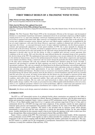
- 2. Proceedings of COBEM 2009 20th International Congress of Mechanical Engineering Copyright © 2009 by ABCM November 15-20, 2009, Gramado, RS, Brazil Figure 1 also shows the most important components for the good flow quality in the test section. The cylindrical stilling chamber provides a length for the flow to settle and become uniform. It provides two screens and one honeycomb for promoting uniformity of flow and for reducing turbulence in the air stream. Finally, the air is exhausted into the contraction inlet. The contraction provides a change in the geometry from circular (as in the outlet of the stilling chamber) to rectangular (as in the inlet of the first throat). The first throat, whose design is the objective of the present work, basically promotes the acceleration of the flow to reach the prescribed velocity at the test section. This must be done without penalizing the flow quality already obtained in the stilling chamber. Flow quality can be defined as the spatial and temporal distributions of the flow parameters in the test section; particularly the Mach number, flow angle, and temperature. The flow quality criteria for these parameters has direct influence on the quality of the aerodynamic characteristics CL, CD, Cm, (lift, drag and pitch moment coefficients) (Bertin and Smith, 1998) From the practical standing point, a good flow quality in high speed wind tunnels can be obtained when the Mach number accuracy in test section is one drag count (one drag count is 0.0001) in the evaluation of the CD. To provide a single drag count accuracy, the free Mach number must be determined and kept constant through a sweep of complete angle of attack within |∆M| ≤ 0.001. In addition, it is desirable to have a two-sigma deviation in Mach number over the region of the model of |2σM| ≤ 0.001. These criteria are imposed to stretch the capabilities of well-designed transonic wind tunnels (Davis et al., 1986). The first throat of PTT, as for most high speed tunnels, is rectangular. The ceiling and the floor are parallel, and the side walls are specially contoured, fabricated into a rigid semi-permanent assembly, and it is inserted into the tunnel circuit with the help of bolted flanges. Some high speed tunnels have flexible nozzle with automatically operated jacks to conform the first throat geometry for all kind of tests. However, PTT has one sonic nozzle which allows tests from subsonic until low supersonic speeds (Mach number around 1.15), and new convergent-divergent nozzles must be installed in order to reach supersonic conditions at the test section. The present work describes the main steps followed during the conceptual design of a new convergent-divergent nozzle for the first throat of PTT for the sought Mach number 1.3 at the test section. The design must be done with special care to allow good agreement between other components from the tunnel aerodynamic circuit – contraction outlet and test section inlet. The second throat also has an important role in supersonic regime. It reduces the flow Mach number and causes a localized shock reducing pressure loss in the tunnel circuit. The test section is involved by a volume called plenum chamber where the pressure is adjusted in order to control the mass flow through the longitudinal slots of the test section walls. Plenum Chamber Main Compressor High-speed Diffuser Cooler Test Section Injectors First Throat Stilling Chamber Contraction Second Throat Figure 1 – PTT aerodynamic circuit scheme. It is used a mathematical design tool developed after the method proposed by Foelsh (1949), based on the method of characteristics to determine a non viscous solution for the wall geometry, allowing compression and expansion waves cancellation. A numerical code developed to calculate the Euler Equations is also used to verify the nozzle behavior at some operational conditions. 2. STATEMENT OF THE PROBLEM Section area variation, friction and heat transfer are the most significant items that affect the flow properties. Even though some situations comprise simultaneous effects of these three factors, the engineering problems are dominated by
- 3. Proceedings of COBEM 2009 20th International Congress of Mechanical Engineering Copyright © 2009 by ABCM November 15-20, 2009, Gramado, RS, Brazil just one; the section area variation. Because of this, the high speed flow regions require special attention in a wind tunnel design. It will determine, among other factors, the flow velocity at the test section. The development of efficient converging-diverging supersonic nozzles is not simple. It requires the understanding of the reflection effects of compression/expansion waves and their mutual cancelling. If the nozzle is not well developed, there will be shocks in the test section, and the flow will not be uniform. Figure 2 shows the complete region to be calculated, nominating the sub-regions and the main interesting points. This shown region consists of three elements from the aerodynamic circuit: contraction, first throat and test section. A compressible fluid with a very low velocity at the stagnation chamber reaches the contraction section (1) where it is accelerated. Next, the flow continues to be accelerated in the first throat (2), and attains the sonic velocity at the geometric throat (3). Then the fluid is expanded up to the desired Mach number at the section inlet (5) of the nozzle, where the flow must be kept uniform and parallel up to its end (6). The expansion that occurs in the region between the throat (3) and the test section entrance (5) can be divided in two different regions, the first one having a smooth increasing of the derivative of the area with respect to the tunnel length, and the second with a smooth decreasing of this area derivative, therefore establishing an interface point – the inflexion point – where the second derivative of the area is equal to zero. First Throat Test Section 1 2 3 4 5 6 Contraction Figure 2 – Nozzle Section of a Supersonic Wind Tunnel. At the beginning, the idea was to model the PTT geometry with the help of bi-dimensional coordinates. Since the contraction section is eminently a tri-dimensional geometry, with area changing from circular to rectangular, it is adopted a constant height, equal to the common height of the first throat and the test section. This way, an equivalent width at each local in the contraction is determined, based on the same area of the original installation. It is evident that this imposes an important restriction to the problem, since the flow that is going into the contraction section is tri- dimensional. However, it is proved by the numerical results that this kind of approximation does not affect the observed phenomena in the test section at the supersonic regime, and that this is much more influenced by the geometric changes in divergent region (regions numbered from 3 to 5 in Fig. 2). 3. FIRST THROAT DESIGN The original geometry developed to be used in PTT for a converging-diverging first throat was initially considered. Since the first results showed that the flow uniformity in test section was not so good for that geometry, another idea, based in a theoretical approach, was considered. It follows the description of the main idea behind this above mentioned approach. Many methodologies applied to the first throat design are initially based in assumptions of isentropic flow, being later incorporated boundary layer corrections. The algebra basis of nozzles calculus theory is the method of characteristics, stated by Busemann and Prandtl in 1929. Most of the researchers adopt this methodology with some variations. As it can be seen in Fig. 2, the divergent region of the first throat may be divided in two regions by the inflection point. The method of characteristics may be addressed after starting with the simple consideration of flow passing by corners. An analysis of compression and expansion wave intersections can show how to choose the geometry to obtain cancellation of effects. This technique, starting at the inflection point, moving initially to the throat and later, from the inflection point to the test section, is known as the Foelsch Method (Foelsch, 1949). It has the great
- 4. Proceedings of COBEM 2009 20th International Congress of Mechanical Engineering Copyright © 2009 by ABCM November 15-20, 2009, Gramado, RS, Brazil advantage of being analytical, allowing ease implementation of numerical algorithm. This way, an available numerical code due to Belderrain and Abreu (1978) is used to obtain new first throat designs. Usually, the convergent region is approached by some empirical way, following criteria of geometric smoothness and small angles. In the present work, it was adopted the original design. However, the divergent region play important role in supersonic regime and its design requires great care because of the shock and expansion waves that appear. The first part of the divergent (from the throat to the inflection point, regions 3 to 4 in Fig. 2) may be chosen arbitrarily, provided that the geometric angle is compatible with the next curve. The experience shows that a good candidate is the curve − + = 1 2 1 1 0 3 1 x x x x tg y y θ , (1) where, x and y are the curve coordinates, stream wise and orthogonal to stream wise direction, respectively, and x1 is the distance from the throat to the inflection point, y0 is half height at the throat location, and θ1 is the initial angle of expansion (angle at the inflection point). Imposing to the Eq. (2) the restrictions to the inflection point, one can find the inflection point coordinates, ( ) 1 0 1 1 2 3 θ ctg y y x − = . (2) The second part of the divergent (from the inflection point to the test section entrance, 4 to 5 in Fig. 2) must be calculated after the algorithm proposed by Foelsh (1949), to allow that the compression waves could precisely cancel the expansion waves generated in the first part. This way, the flow will reach the test section entrance with good uniformity. A detailed explanation of the method here would be beyond the scope of this article and it is suggested to the reader to look for it in Belderrain and Abreu (1978), as well in Foelsh (1949). 4. FIRST THROAT ANALYSIS STRATEGY The test section must be assessed in terms of its most important characteristic, which is uniformity, observing essentially the existence of shock wave reflections of considerable intensity on the walls. A numerical code to solve the Euler Equations, based on the implicit approximate factorization originally proposed by Beam and Warming (1978), was used to analyze the flow in the test section. In this method, the space derivatives are approximated using centered schemes, and the time marching is undertaken through implicit Euler method. To simplify the numerical code and consequently to reduce computational cost of the solution, it was adapted to follow the diagonal algorithm of Pulliam and Chaussee (1981), complemented by a non-linear, spectral-radius-based artificial dissipation strategy due to Pulliam (1986). This implementation maintains the whole stability characteristics and accuracy in stationary state applications (Falcão Filho, 2006). 4.1. MATHEMATICAL MODELING The Euler Equations written in bi-dimensional, generalized body-conforming coordinates, and in conservation-law form, is given by (Anderson, 1984) 0 = ∂ ∂ + ∂ ∂ + ∂ ∂ η ξ τ F E Q , (3) and the variable-conserved vector is given by [ ] e v u J Q ρ ρ ρ 1 − = , (4) where ρ is density, u and v are velocity cartesian coordinates and e is total energy. And the non-viscous flux vectors are
- 5. Proceedings of COBEM 2009 20th International Congress of Mechanical Engineering Copyright © 2009 by ABCM November 15-20, 2009, Gramado, RS, Brazil , ) ( 1 − + + + = − t y x p U p e p vU p uU U J E ξ ξ ρ ξ ρ ρ (5) , ) ( 1 − + + + = − t y x p V p e p vV p uV V J F η η ρ η ρ ρ (6) where p is static pressure. Adopting the perfect gas hypotheses, p may be expressed by: . ) ( 2 1 ) 1 ( 2 2 + − − = v u e p ρ γ ρ (7) The curvilinear coordinate system is defined such that ξ is the direction following the channel walls, the computational direction i, and η is the transversal direction from the points on the channel walls, the computational direction j. This coordinate system is obtained from the Cartesian system (x, y) through the relations t = τ , ( ) y x t , , ξ ξ = , (8) ( ) y x t , , η η = . and the transformation jacobian is given by 1 ) ( − − = ξ η η ξ y x y x J . (9) The contra-variant velocity components are defined as v u U y x t ξ ξ ξ + + = , (10) v u V y x t η η η + + = . (11) 4.2. MESH, BOUNDARY AND INITIAL CONDITIONS A program developed in Fortran to create algebraic finite-difference bi-dimensional meshes was used for the computational analysis of the design solutions. Initially, the meshes were created by using the PTT original geometry, as described in Section 2, between the entrance of the contraction section and the end of the test section, represented in Fig. 3. Figure 4 shows a detail of the throat region. The reader is asked to notice that Figs. 3 and 4 are not in scale. One can see that the mesh refinement is finer in the region of the throat than elsewhere, in order to define more precisely the origin of the expansion waves. To the left, the mesh is less refined, since the main physical phenomena are present mostly near the throat, in higher speed regime. To the right, the refinement is maintained in a reasonable level up to the test section entrance and it was kept constant along all the test section length. A stretching procedure was also tested but it failed, as will be shown in the results section. The total mesh has 679 x 121 points, with a minimum longitudinal grid displacement of 0.002 m and a minimum transversal grid displacement of 0.002 m.
- 6. Proceedings of COBEM 2009 20th International Congress of Mechanical Engineering Copyright © 2009 by ABCM November 15-20, 2009, Gramado, RS, Brazil Figure 3 – Calculation mesh. Figure 4 – Detail of the mesh near the throat region. A first attempt to run the code by using a mesh since from the entrance of the first throat failed, because the flow should be precisely specified at that location and there was no information about it. So, the contraction was included in the calculation mesh in a way that fixes near stagnation conditions at the contraction entrance, facilitating enormously the solution convergence. The well known strategy used in convergent-divergent nozzles operating in supersonic regimes is used (Falcão Filho et al., 2000). This approach imposes conditions at the channel entrance and a low pressure condition at the channel exit. As the numerical code evolutes the flow is accelerated imitating the real physics. At the moment when the stream-wise velocity reaches supersonic condition, the code logic changes the boundary condition at the exit plane to a simple parabolic extrapolation, guaranteeing a good representation of the real physics. In all simulated cases the numerical convergence was very good. The conditions established at the contraction entrance, obtained from the tunnel theoretical calculations, were pressure of 1.012 bar, temperature of 14.7 C, velocity of 11.6 m/s. Adiabatic conditions were applied to the solid boundaries. 5. RESULTS The first study case was obtained with the original design of the PTT. The convergent-divergent nozzle has appropriate contour to obtain Mach number 1.3 at the exit. Figure 5 shows the results of Mach number field for the original design. It can be seen the acceleration of the flow since the contraction section entrance to the test section end. 0.5 1 1.5 2 2.5 3 Throat Test Section Beginning
- 7. Proceedings of COBEM 2009 20th International Congress of Mechanical Engineering Copyright © 2009 by ABCM November 15-20, 2009, Gramado, RS, Brazil One can see some shock formation at the test section entrance, being reflected by the walls. In order to obtain a better visualization of the Mach number distribution, another kind of plot is more useful. Figure 6 shows the Mach number distribution at the center line since the contraction entrance to test section end. It can be observed numerically the flow quality in the test section. One can also observe how smooth is the flow acceleration through the contraction and the first throat. However, in test section, it is evident that the flow distribution is not good, revealing the presence of shocks. The observed Mach number deviation was 0.050. This value is too high, when compared to the requirement of |2σM| ≤ 0.001 (Davis et al., 1986). This fact provides evidence that the first throat designed is of poor quality. Figure 5 – Results for the original contour. The two dashed lines mark the beginning and the end of the first throat. 0 0.2 0.4 0.6 0.8 1 1.2 1.4 1.6 0 0.5 1 1.5 2 2.5 Streamwise distance (m) Mach number Figure 6 – Mach number distribution at the center line of the tunnel for the original contour. The two dashed lines mark the beginning and the end of the first throat. Since the non-uniformities found in the test section are exclusively due to the wall contours, an investigation of the smoothness can clarify the fact. Figure 7 shows the geometric derivative at the walls, along the whole domain. The
- 8. Proceedings of COBEM 2009 20th International Congress of Mechanical Engineering Copyright © 2009 by ABCM November 15-20, 2009, Gramado, RS, Brazil dashed lines mark the inlet and the throat location of the first throat section. Observe the poor quality of the derivatives just after the throat. Certainly this can explain the shock waves that appeared in the test section. -4.5 -4 -3.5 -3 -2.5 -2 -1.5 -1 -0.5 0 0.5 0.00 500.00 1000.00 1500.00 2000.00 Figure 7 – Geometric derivatives at the wall along the whole domain. The dashed lines mark the inlet and the throat of the first throat. The second study case was based on this former one, trying to smooth all derivatives along the tunnel walls. For this, some empirical approximations were tried in a tentative way. Figure 8 shows the numerical result obtained with this new geometry, using the same Mach number plotting levels as encountered in Fig. 5. It is clear that the uniformity into the test section was improved. Figure 8 – Results for the adapted contour. The two dashed lines mark the beginning and the end of the first throat. Figure 9 shows the Mach number distribution for the adapted original design. It can be seen in this figure that the flow distribution is better than the original, only being observed a small periodic disturbance. The observed Mach
- 9. Proceedings of COBEM 2009 20th International Congress of Mechanical Engineering Copyright © 2009 by ABCM November 15-20, 2009, Gramado, RS, Brazil number variation was 0.004. This value is close to the required value (|2σM| ≤ 0.001). This fact proves that the first throat with the contour modified has better quality. 0 0.2 0.4 0.6 0.8 1 1.2 1.4 0 0.5 1 1.5 2 2.5 3 3.5 Streamwise distance (m) Mach number Figure 9 – Mach number distribution at the center line of the tunnel for the adapted contour. The two dashed lines mark the beginning and the end of the first throat. The third case of study was obtained using the Foelsh method for the design of the convergent-divergent nozzle, restricted to the PTT aerodynamic circuit dimensions. The geometry of the contraction section, test section and the first throat length were the same as encountered in PTT design. A new geometry for the walls of the first throat was calculated and a new mesh created. Figure 10 shows the Mach number field for this case, where one can see that, when compared to the other cases shown in Figs. 5 and 8, this case has similarities with the first one, and that there are still appreciable disturbances in the test section. Figure 10 – Results for the contour as determined by Foelsh Method.
- 10. Proceedings of COBEM 2009 20th International Congress of Mechanical Engineering Copyright © 2009 by ABCM November 15-20, 2009, Gramado, RS, Brazil This fact can be clarified in Fig. 11, with a Mach number distribution at the center line of the tunnel, where it can be observed a Mach number deviation of 0.016, that is a value still high, compared with the requirements (|2σM| ≤ 0.001). It is interesting that it was detected a variation in the inclination of the curve shown in Fig. 11, near the throat, giving an idea of possible reasons for the disturbances in test section. This fact also shows that the initial equation which describes the wall contour between the throat and the inflection point (see Fig. 2) seems to be not so effective. The search for a more effective empirical equation is still an ongoing process in this research. 0 0.2 0.4 0.6 0.8 1 1.2 1.4 0 0.5 1 1.5 2 2.5 3 3.5 Streamwise distance (m) Mach number Figure 11 – Mach number distribution on the center line of the tunnel for the contour calculated by Foelsh Method. The two dashed lines mark the beginning and the end of the first throat. Among some tests intended to verify the numerical calculation accuracy, one is worth noting. Using the last study case, it was tried a stretching procedure of 10% with the points in the test section in stream wise direction, between the test section at the entrance and the section at half of its length, where it was adopted a constant grid displacement as far as its end. Figure 12 shows the resulted Mach number distribution at the center line, compared with the solution with constant grid. A small deviation in the frequency and the intensity of the shocks were noted in the solution with grid stretching. This fact can be explained by the artificial dissipation necessary with numerical code based on centered difference, which responds differently at different grid clustering. Although the numerical impact was small, only the mesh with constant, as described in the item 4.2 was adopted for all study cases.
- 11. Proceedings of COBEM 2009 20th International Congress of Mechanical Engineering Copyright © 2009 by ABCM November 15-20, 2009, Gramado, RS, Brazil 0 0.2 0.4 0.6 0.8 1 1.2 1.4 0 0.5 1 1.5 2 2.5 3 3.5 Streamwise distance (m) Mach number Figure 12 – Mach number distribution at the center line of the tunnel for the contour calculated by Foelsh Method, comparing with stretching mesh solution. 5. CONCLUSIONS The design of the supersonic convergent-divergent first throat of a transonic wind tunnel was addressed, being given directions to the use of the Foelsh Method, based on the method of characteristics, in order to obtain a good solution to be applied to the PTT of the Aerodynamics Division of the Institute of Aeronautics and Space. The approach given by the present work is very important for the future of the PTT, once new designs will be possible to be constructed, expanding the tunnel capabilities in supersonic regimes. A brief description of the tunnel and the use of the first throat are presented. A numerical code developed to calculate the Euler Equations with the objective of verifying the nozzle behavior at some operational conditions was described. The code was originally developed based on the Beam and Warming centered finite-differences scheme, alternating-direction-implicit algorithm, applied to a bi-dimensional, body- conforming reference system, with the time marching using first-order Euler approximation. It was later modified to use the diagonal algorithm, firstly developed by Pulliam and Chaussee. Three study cases were tackled and presented. Initially, the original design intended for PTT was analyzed, and it showed to be of poor quality. Then, after some empirical smoothness procedure applied to the walls geometric derivatives, a second case was established, and showed to reach good agreement with the requirements for Mach number deviation in test section, according to applicable literature (|2σM| ≤ 0.001). Finally, a study case based on the solution obtained from the Foelsh Method was analyzed, which showed the need of better adjustments in the arbitrary geometry that was established just after the throat. In all study cases Mach number field is analyzed, as well as a Mach number center line distribution, to better investigate shock waves formation in test section. At the end it is shown a grid stretching effect in test section. 6. ACKNOWLEDGEMENTS The authors would like to express their gratitude to the National Council for Scientific and Technological Development (CNPq) for the partial funding of this research under Grant n. 100656/2009-9. 7. REFERENCES Anderson, D. A., Tannehill, J. C., Pletcher, R. H., 1984, Computational Fluid Mechanics and Heat Transfer, Hemisphere Publishing Corp. Beam, R. M., Warming, R. F., 1978, “An implicit factored scheme for the compressible Navier Stokes Equations”, AIAA Journal, Vol. 16, nº4.
- 12. Proceedings of COBEM 2009 20th International Congress of Mechanical Engineering Copyright © 2009 by ABCM November 15-20, 2009, Gramado, RS, Brazil Belderrain, J. L. R., Abreu, F. L., 1978, “Anteprojeto de um Túnel de Vento Supersônico,” final undergraduate work from ITA – Technological Institute of Aeronautics. Bertin, J. J., Smith, M. L., 1998, Aerodynamics for Engineers, third edition, Prentice Hall, New Jersey. Davis, M. W., Gunn, J. A., Herron, R. D., Kraft, E. M., 1986, “Optimum transonic wind tunnel,” AIAA 14th Aerodynamic Testing Conference, 14, West Palm Beach, AIAA-86-0756-CP. Falcão Filho, J. B. P., Ortega, M. A., Fico Jr., N. G. C. R., 2000, “On the Implementation of a Finite-Difference Computer Code for the Calculation of Compressible Transonic/Supersonic Viscous Flows,” Proceedings ... VIII Brazilian Congress of Thermal Sciences and Engineering, ENCIT-2000, Porto Alegre-RS, article S01P29. Falcão Filho, J. B. P., Mello, O. A. F., 2002, “Descrição Técnica do Túnel Transônico Piloto do Centro Técnico Aeroespacial,” Congresso Brasileiro de Ciências Térmicas e Engenharia, ENCIT-2002. Falcão Filho, J. B. P., 2006, “Estudo Numérico do Processo de Injeção em um Túnel de Vento Transônico,” Tese de Doutorado, ITA, São José dos Campos. Foelsch, K., 1949, “The Analytical Design of an Axially Symmetric Laval Nozzle for a Parallel and Uniform Jet.” Journal of the Aeronautical Sciences, 16(3), 161-166. Pope, A., Goin, K. L., 1978, High-speed wind tunnel testing, New York: John Wiley & Sons. Pulliam, T. H., Chaussee, D. S., 1981, “A diagonal form of an implicit aproxímate-factorization algorithm”, Journal of Computational Physics, Vol. 39. Pulliam, T. H., 1986, “Artificial dissipation models for the Euler Equations”, AIAA Journal, Vol. 24, nº12. 8. RESPONSIBILITY NOTICE The author(s) is (are) the only responsible for the printed material included in this paper.