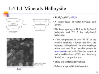
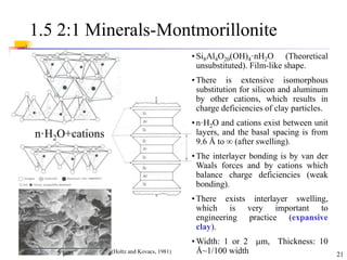
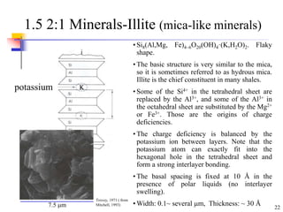
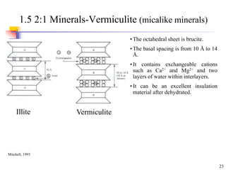
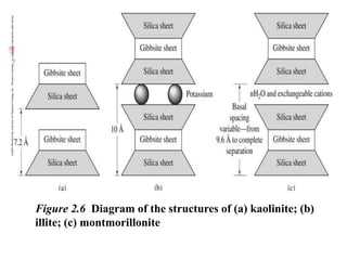
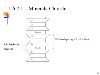
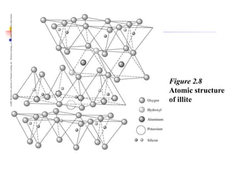
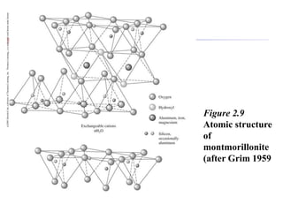
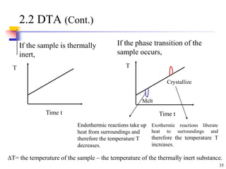
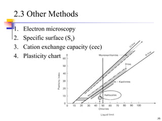
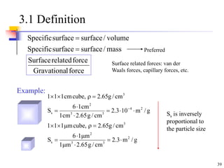
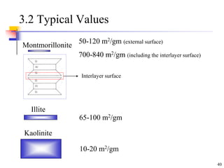
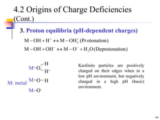
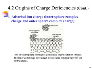
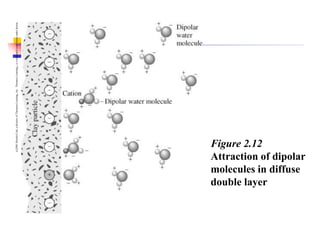
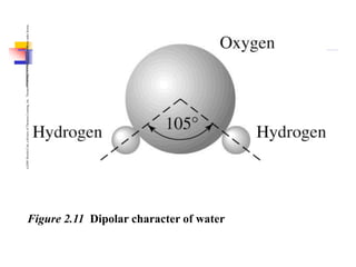
SlideShare a Scribd company logo
1
Clay Minerals and Soil Structure
2
Outline
1. Clay Minerals
2. Identification of Clay Minerals
3. Specific Surface (Ss)
4. Interaction of Water and Clay Minerals
5. Interaction of Clay Particles
6. Soil Structure and Fabric
7. Soil Fabric-Natural Soil
8. Soil Fabric-Clay Soils
9. Soil Fabrics-Granular Soils
10. Loess
11. Suggested Homework
12. References
3
1. Clay Minerals
Parent Rock
~ formed by one of these three different processes
igneous sedimentary metamorphic
formed by cooling of
molten magma (lava)
formed by gradual
deposition, and in layers
formed by alteration
of igneous &
sedimentary rocks by
pressure/temperature
e.g., limestone, shale
e.g., marble
e.g., granite
5
Residual Soils
Formed by in situ weathering of parent rock
6
Transported Soils
Transported by: Special name:
 wind “Aeolian”
sea (salt water) “Marine”
lake (fresh water) “Lacustrine”
river “Alluvial”
ice “Glacial”
(c)2001
Brooks/Cole,
a
division
of
Thomson
Learning,
Inc.
Thomson
Learning
™
is
a
trademark
used
herein
under
license.
Figure 2.3A Mechanical erosion due to ocean
waves and wind at Yehliu, Taiwan
(c)2001
Brooks/Cole,
a
division
of
Thomson
Learning,
Inc.
Thomson
Learning
™
is
a
trademark
used
herein
under
license.
Figure 2.3B (cont.) Mechanical
erosion due to ocean waves and
wind at Yehliu, Taiwan
(c)2001
Brooks/Cole,
a
division
of
Thomson
Learning,
Inc.
Thomson
Learning
™
is
a
trademark
used
herein
under
license.
Figure 2.3C (cont.) Mechanical erosion due to
ocean waves and wind at Yehliu, Taiwan
(c)2001
Brooks/Cole,
a
division
of
Thomson
Learning,
Inc.
Thomson
Learning
™
is
a
trademark
used
herein
under
license.
Figure 2.3 D (cont.)
Mechanical erosion due
to ocean waves and
wind at Yehliu, Taiwan
(c)2001
Brooks/Cole,
a
division
of
Thomson
Learning,
Inc.
Thomson
Learning
™
is
a
trademark
used
herein
under
license.
Figure 2.3E (cont.)
Mechanical erosion due
to ocean waves and
wind at Yehliu, Taiwan
Figure 2.7
Scanning electron
micrograph of a
kaolinite specimen
(courtesy of U.S.
Geological
Survey)
13
1.1 Origin of Clay Minerals
“The contact of rocks and water produces clays, either at or near the surface
of the earth” (from Velde, 1995).
Rock +Water  Clay
For example,
The CO2 gas can dissolve in water and form carbonic acid, which will
become hydrogen ions H+ and bicarbonate ions, and make water slightly
acidic.
CO2+H2O  H2CO3 H+ +HCO3
-
The acidic water will react with the rock surfaces and tend to dissolve the K
ion and silica from the feldspar. Finally, the feldspar is transformed into
kaolinite.
Feldspar + hydrogen ions+water  clay (kaolinite) + cations, dissolved silica
2KAlSi3O8+2H+ +H2O  Al2Si2O5(OH)4 + 2K+ +4SiO2
•Note that the hydrogen ion displaces the cations.
14
1.1 Origin of Clay Minerals (Cont.)
• The alternation of feldspar into kaolinite is very common
in the decomposed granite.
• The clay minerals are common in the filling materials of
joints and faults (fault gouge, seam) in the rock mass.
Weak plane!
15
1.2 Basic Unit-Silica Tetrahedra
Hexagonal
hole
1 Si
4 O
(Si2O10)-4
Replace four
Oxygen with
hydroxyls or
combine with
positive union
(Holtz and Kovacs, 1981)
Tetrahedron
Plural: Tetrahedra
16
1.2 Basic Unit-Octahedral Sheet
Gibbsite sheet: Al3+
Al2(OH)6, 2/3 cationic spaces are filled
One OH is surrounded by 2 Al:
Dioctahedral sheet
Brucite sheet: Mg2+
Mg3(OH)6, all cationic spaces
are filled
One OH is surrounded by 3 Mg:
Trioctahedral sheet
Different
cations
1 Cation
6 O or OH
(Holtz and Kovacs, 1981)
17
1.2 Basic Unit-Summary
Mitchell, 1993
18
1.3 Synthesis
Noncrystall
ine clay -
allophane
Mitchell, 1993
19
1.4 1:1 Minerals-Kaolinite
Basal spacing is 7.2 Å
• Si4Al4O10(OH)8. Platy shape
• The bonding between layers are van der
Waals forces and hydrogen bonds (strong
bonding).
• There is no interlayer swelling
• Width: 0.1~ 4m, Thickness: 0.05~2 m
layer
Trovey, 1971 ( from
Mitchell, 1993)
17 m
20
1.4 1:1 Minerals-Halloysite
• Si4Al4O10(OH)8·4H2O
• A single layer of water between unit
layers.
• The basal spacing is 10.1 Å for hydrated
halloysite and 7.2 Å for dehydrated
halloysite.
• If the temperature is over 50 °C or the
relative humidity is lower than 50%, the
hydrated halloysite will lose its interlayer
water (Irfan, 1966). Note that this process is
irreversible and will affect the results of
soil classifications (GSD and Atterberg
limits) and compaction tests.
• There is no interlayer swelling.
• Tubular shape while it is hydrated.
Trovey, 1971 ( from
Mitchell, 1993)
2 m
21
1.5 2:1 Minerals-Montmorillonite
n·H2O+cations
5 m
• Si8Al4O20(OH)4·nH2O (Theoretical
unsubstituted). Film-like shape.
• There is extensive isomorphous
substitution for silicon and aluminum
by other cations, which results in
charge deficiencies of clay particles.
• n·H2O and cations exist between unit
layers, and the basal spacing is from
9.6 Å to  (after swelling).
• The interlayer bonding is by van der
Waals forces and by cations which
balance charge deficiencies (weak
bonding).
• There exists interlayer swelling,
which is very important to
engineering practice (expansive
clay).
• Width: 1 or 2 m, Thickness: 10
Å~1/100 width
(Holtz and Kovacs, 1981)
22
1.5 2:1 Minerals-Illite (mica-like minerals)
potassium
• Si8(Al,Mg, Fe)4~6O20(OH)4·(K,H2O)2. Flaky
shape.
• The basic structure is very similar to the mica,
so it is sometimes referred to as hydrous mica.
Illite is the chief constituent in many shales.
• Some of the Si4+ in the tetrahedral sheet are
replaced by the Al3+, and some of the Al3+ in
the octahedral sheet are substituted by the Mg2+
or Fe3+. Those are the origins of charge
deficiencies.
• The charge deficiency is balanced by the
potassium ion between layers. Note that the
potassium atom can exactly fit into the
hexagonal hole in the tetrahedral sheet and
form a strong interlayer bonding.
• The basal spacing is fixed at 10 Å in the
presence of polar liquids (no interlayer
swelling).
• Width: 0.1~ several m, Thickness: ~ 30 Å
7.5 m
Trovey, 1971 ( from
Mitchell, 1993)
K
23
1.5 2:1 Minerals-Vermiculite (micalike minerals)
• The octahedral sheet is brucite.
• The basal spacing is from 10 Å to 14
Å.
• It contains exchangeable cations
such as Ca2+ and Mg2+ and two
layers of water within interlayers.
• It can be an excellent insulation
material after dehydrated.
Illite Vermiculite
Mitchell, 1993
(c)2001
Brooks/Cole,
a
division
of
Thomson
Learning,
Inc.
Thomson
Learning
™
is
a
trademark
used
herein
under
license.
Figure 2.6 Diagram of the structures of (a) kaolinite; (b)
illite; (c) montmorillonite
25
1.6 2:1:1 Minerals-Chlorite
The basal spacing is fixed at 14 Å.
Gibbsite or
brucite
(c)2001
Brooks/Cole,
a
division
of
Thomson
Learning,
Inc.
Thomson
Learning
™
is
a
trademark
used
herein
under
license.
Figure 2.8
Atomic structure
of illite
(c)2001
Brooks/Cole,
a
division
of
Thomson
Learning,
Inc.
Thomson
Learning
™
is
a
trademark
used
herein
under
license.
Figure 2.4 (a) Silica
tetrahedron; (b)
silica sheet; (c)
alumina
octahedron; (d)
octahedral
(gibbsite) sheet; (e)
elemental silica-
gibbsite sheet;
(after Grim, 1959)
(c)2001
Brooks/Cole,
a
division
of
Thomson
Learning,
Inc.
Thomson
Learning
™
is
a
trademark
used
herein
under
license.
Figure 2.9
Atomic structure
of
montmorillonite
(after Grim 1959
29
1.7 Chain Structure Clay Minerals
• They have lathlike or threadlike
morphologies.
• The particle diameters are from 50 to
100 Å and the length is up to 4 to 5
m.
• Attapulgite is useful as a drilling
mud in saline environment due to its
high stability.
4.7 m
Trovey, 1971 ( from Mitchell, 1993)
Attapulgite
30
1.8 Mixed Layer Clays
• Different types of clay minerals have similar structures (tetrahedral and
octahedral sheets) so that interstratification of layers of different clay
minerals can be observed.
• In general, the mixed layer clays are composed of interstratification of
expanded water-bearing layers and non-water-bearing layers.
Montmorillonite-illite is most common, and chlorite-vermiculite and
chlorite-montmorillonite are often found.
(Mitchell, 1993)
31
1.9 Noncrystalline Clay Materials
Allophane
Allophane is X-ray amorphous and has no definite
composition or shape. It is composed of hollow,
irregular spherical particles with diameters of 3.5 to
5.0 nm.
32
2. Identification of Clay Minerals
33
2.1 X-ray diffraction
• The distance of atomic planes d can be determined based on the Bragg’s
equation.
BC+CD = n, n = 2d·sin, d = n/2 sin
where n is an integer and  is the wavelength.
• Different clays minerals have various basal spacing (atomic planes). For
example, the basing spacing of kaolinite is 7.2 Å.
Mitchell, 1993
34
2.2 Differential Thermal Analysis (DTA)
For example:
Quartz changes from the  to  form at 573 ºC
and an endothermic peak can be observed.
• Differential thermal analysis
(DTA) consists of simultaneously
heating a test sample and a
thermally inert substance at
constant rate (usually about 10
ºC/min) to over 1000 ºC and
continuously measuring differences
in temperature and the inert
material T.
• Endothermic (take up heat) or
exothermic (liberate heat) reactions
can take place at different heating
temperatures. The mineral types
can be characterized based on those
signatures shown in the left figure.
(from Mitchell, 1993)
T
Temperature (100 ºC)
35
2.2 DTA (Cont.)
If the sample is thermally
inert,
If the phase transition of the
sample occurs,
T
Time t
T
Time t
Crystallize
Melt
Endothermic reactions take up
heat from surroundings and
therefore the temperature T
decreases.
Exothermic reactions liberate
heat to surroundings and
therefore the temperature T
increases.
T= the temperature of the sample – the temperature of the thermally inert substance.
36
2.3 Other Methods
1. Electron microscopy
2. Specific surface (Ss)
3. Cation exchange capacity (cec)
4. Plasticity chart
37
2.3 Other Methods (Cont.)
5. Potassium determination
Well-organized 10Å illite layers contain 9% ~ 10 % K2O.
6. Thermogravimetric analysis
It is based on changes in weight caused by loss of water
or CO2 or gain in oxygen.
Sometimes, you cannot identify clay minerals only based
on one method.
38
3. Specific Surface (Ss)
39
3.1 Definition
force
l
Gravationa
force
related
Surface
mass
/
surface
surface
Specific
volume
/
surface
surface
Specific


g
/
m
3
.
2
cm
/
g
65
.
2
m
1
m
1
6
S
cm
/
g
65
.
2
,
cube
m
1
1
1
g
/
m
10
3
.
2
cm
/
g
65
.
2
cm
1
cm
1
6
S
cm
/
g
65
.
2
,
cube
cm
1
1
1
2
3
3
2
s
3
2
4
3
3
2
s
3























Example:
Surface related forces: van der
Waals forces, capillary forces, etc.
Ss is inversely
proportional to
the particle size
Preferred
40
3.2 Typical Values
Montmorillonite
Illite
Kaolinite
50-120 m2/gm (external surface)
700-840 m2/gm (including the interlayer surface)
65-100 m2/gm
10-20 m2/gm
Interlayer surface
41
4. Interaction of Water and Clay
Minerals
42
4.1 Origins of Charge Deficiencies
1. Imperfections in the crystal lattice -
Isomorphous substitution.
• The cations in the octahedral or tetrahedral sheet can be replaced by
different kinds of cations without change in crystal structure
(similar physical size of cations).
For example,
Al3+ in place of Si4+ (Tetrahedral sheet)
Mg2+ instead of Al3+(Octahedral sheet)
unbalanced charges (charge deficiencies)
• This is the main source of charge deficiencies for montmorillonite.
• Only minor isomorphous substitution takes place in kaolinite.
43
4.2 Origins of Charge Deficiencies
(Cont.)
2. Imperfections in the crystal lattice
- The broken edge
The broken edge can be
positively or negatively
charged.
44
4.2 Origins of Charge Deficiencies
(Cont.)
3. Proton equilibria (pH-dependent charges)
)
ion
Deprotonat
(
O
H
O
M
OH
OH
M
)
otonation
(Pr
OH
M
H
OH
M
2
2













Kaolinite particles are positively
charged on their edges when in a
low pH environment, but negatively
charged in a high pH (basic)
environment.
M
M
M
O
O-
O
H+
H
H
M: metal
45
4.2 Origins of Charge Deficiencies (Cont.)
4. Adsorbed ion charge (inner sphere complex
charge and outer sphere complex charge)
Ions of outer sphere complexes do not lose their hydration spheres.
The inner complexes have direct electrostatic bonding between the
central atoms.
46
4.3 “Charged” Clay Particles
• External or interlayer surfaces are
negatively charged in general.
• The edges can be positively or
negatively charged.
• Different cations balance charge
deficiencies.
Dry condition
- or +
- or +
Cation
Kaolinite and negative gold sol
(van Olphen, 1991)
(c)2001
Brooks/Cole,
a
division
of
Thomson
Learning,
Inc.
Thomson
Learning
™
is
a
trademark
used
herein
under
license.
Figure 2.12
Attraction of dipolar
molecules in diffuse
double layer
48
4.4 Polar Water Molecules
Structure Polar molecule
H(+) H(+)
O(-)
Hydrogen bond Salts in aqueous solution
hydration
(c)2001
Brooks/Cole,
a
division
of
Thomson
Learning,
Inc.
Thomson
Learning
™
is
a
trademark
used
herein
under
license.
Figure 2.11 Dipolar character of water
50
Adsorbed layers
3 monolayers
4.5 Clay-Water Interaction
1. Hydrogen bond
Kaolinite
Oxygen Hydroxyl
Clay
Surfaces
Free water
Bulk water
The water molecule “locked” in the adsorbed
layers has different properties compared to
that of the bulk water due to the strong
attraction from the surface.
O OH
H
O
H
O
H
O
H
H
51
4.5 Clay-Water Interaction (Cont.)
The water molecules
wedge into the interlayer
after adding water
2. Ion hydration
Dry condition
(Interlayer)
Clay
layers
cation
The cations are fully hydrated,
which results in repulsive forces
and expanding clay layers
(hydration energy).
Na+ crystal radius: 0.095 nm
radius of hydrated ion: 0.358 nm
52
4.5 Clay-Water Interaction (Cont.)
The concentration of cations is higher in the interlayers (A) compared with that
in the solution (B) due to negatively charged surfaces. Because of this
concentration difference, water molecules tend to diffuse toward the interlayer
in an attempt to equalize concentration.
3. Osmotic pressure
From Oxtoby et
al., 1994
A B
53
4.5 Clay-Water Interaction (Cont.)
Relative sizes of adsorbed water layers on sodium montmorillonite and
sodium kaolinite
Holtz and Kovacs, 1981
(c)2001
Brooks/Cole,
a
division
of
Thomson
Learning,
Inc.
Thomson
Learning
™
is
a
trademark
used
herein
under
license.
Figure 2.13 Clay
water (redrawn after
Lambe, 1958
55
5. Interaction of Clay Particles
(or Layers)
Interlayer
Interparticle
Layer
Particle
56
5.1 Diffuse Double Layer
Clay particle with
negatively charged
surface
x Distance x
Concentration
Exponential decay
Cations
Anions
-
-
+
+
-
-
-
-
-
(c)2001
Brooks/Cole,
a
division
of
Thomson
Learning,
Inc.
Thomson
Learning
™
is
a
trademark
used
herein
under
license.
Figure 2.10 Diffuse double layer
58
5.2 Interaction Forces
Net force between clay particles (or interlayers)
= van der Waals attraction +
Double layer repulsion (overlapping of the double layer)+
Coulombian attraction (between the positive edge and negative face)
DLVO
forces
59
5.3 Thickness of Double Layer
Thickness of
double layer K
Valence
:
e
arg
ch
Electron
:
e
ion
concentrat
Cation
:
n
e
Temperatur
:
T
t
tan
cons
Boltzman
:
k
ty
permittivi
lative
Re
:
vacuum
in
ty
Permittivi
:
e
n
2
kT
K
0
0
2
/
1
2
2
0
0
















K  repulsion force 
n0 K  repulsion force 
v  K  repulsion force 
T  K  repulsion force (?)  decreases with increasing
temperature
60
5.4 Interaction of Clay Particles
Dispersed fabric
The net interparticle force
between surfaces is repulsive
Increasing
Electrolyte concentration n0
Ion valence v
Temperature T (?)
Decreasing
Permittivity 
Size of hydration ion
pH
Anion adsorption
•Reduce the double
layer repulsion (only
applicable to some cases)
•Flocculated or
aggregated fabric
Flocculated fabric
Edge-to-face (EF): positively
charged edges and negatively
charged surfaces (more common)
Edge-to-edge (EE)
Aggregated fabric
Face-to-Face (FF) Shifted FF
61
5.4 Interaction of Clay Particles (Cont.)
(1) Decrease pH
(2) Decrease anion adsorption
(3)Size of hydration
Clay
Particle
The total required
number of cations
is 10
+
+
62
5.5 Atterberg Limit of Clay Minerals
Lambe and Whitman, 1979
Na-montmorillonite
•Thicker double layer
•LL=710
Ca-montmorillonite
•Thinner double layer
•LL=510
The thickness of double
layer increases with
decreasing cation valence.
63
5.6 Cation Replaceability
• Different types and quantities of cations are adsorbed to balance charge
deficiencies in clay particles.
• The types of adsorbed cations depend on the depositional environment. For
example, sodium and magnesium are dominant cations in marine clays
since they are common in sea water. In general, calcium and magnesium
are the predominant cations.
• The adsorbed cations are exchangeable (replaceable). For example,
Na Na Na Na
Na Na Na Na
+4CaCl2  +8NaCl
Ca
Ca
Ca
Ca
(Lambe and Whitman, 1979)
64
5.6 Cation Replaceability (Cont.)
The ease of cation replacement
depends on the
(1) Valence (primarily)
 Higher valence cations can replace
cations of lower valence.
(2) Ion size
 Cations with larger non-hydrated
radii or smaller hydrated radii have
greater replacement power.
According to rules (1) and (2), the
general order of replacement is
Li+<Na+<K+<Rb+<Cs+<Mg2+<Ca2+<Ba2+
<Cu2+<Al3+<Fe3+<Th4+
(3) Relative amount
 High concentration of
Na+ can displace Al3+.
Cations
Non-hydrated
radius (Å)
Hydrated
radius (Å)
Li+ 0.68 3.8
Na+ 0.95 3.6
K+ 1.33 3.3
Cs+ 1.69 3.3
Be2+ 0.31 4.6
Mg2+ 0.65 4.3
Ca2+ 0.99 4.1
Ba2+ 1.35
Al3+ 0.5 4.8
Fe3+ 0.6
(Data compiled from
Israelachvili, 1991)
65
5.7 Cation Replaceability (Cont.)
•Hard water softener
Hard water contains soluble calcium and magnesium salts such as
Ca(HCO3)2 and Mg(HCO3)2. The hardness can be removed by exchanging
Ca2+ and Mg2+ with sodium ions Na+. For example,
Na2Z(s) (Zeolite) + Ca2+
(aq)  CaZ(s)+2 Na+
(aq)
As the ion-exchange capacity of Zeolite is saturated, the capacity can be
regained by passing through a concentrated solution of NaCl.
66
5.7 Cation Exchange Capacity (cec)
• The quantity of exchangeable cations is termed the cation
exchangeable capacity (cec) and is usually expressed as
milliequivalents (meq) per 100 gram of dry clay ( from Mitchell, 1993).
• One equivalent = 6.021023 electron charges or 96500 Coulombs, which
is 1 Faraday.
67
5.8 Swelling Potential
Practically speaking, the three ingredients generally necessary for
potentially damaging swelling to occur are (1) presence of
montmorillonite in the soil, (2) the natural water content must be around
the PL, and (3) there must be a source of water for the potentially
swelling clay (Gromko, 1974, from Holtz and Kovacs, 1981)
Holtz and Kovacs, 1981
U.S. Bureau of
Reclamation
68
5.9 Engineering Applications
Lime treatment for the swelling clay
•The swelling clay such as Na-montmorillonite beneath the foundation is
potentially harmful to the light structure. Adding lime (CaO) into such
soil can effectively reduce the swelling potential due to Ca2+ displacing
Na+, and can increase the strength by dehydration of soils and
cementation.
Drilling mud
Soil particle
The swelling clays can
form a so-called “filter
cake” and enable soil
layers to become
relatively impermeable.
Earth
pressure+
ground water
pressure
Pressure
profile of
slurry
Trench
Bentonite or
Polymer
Montmorillonite is the dominant clay mineral in bentonite
Xanthakos, 1991
69
5.9 Engineering Applications (Cont.)
Xanthakos, 1991
70
5.9 Engineering Applications (Cont.)
Xanthakos, 1991
71
5.9 Engineering Applications
Dispersion agents (drilling mud; hydrometer analysis)
• Sodium hexa-metaphosphate (NaPO3) and sodium silicate (Na2SiO3) are used as
the dispersion agent in the hydrometer analysis. How does this dispersion agent
work?
• Three hypotheses:
(1) Edge-charge reversal
The anions adsorption onto the edge of the clay particle may neutralize the positive edge-
charge or further reverse the edge-charge from positive to negative. The edge-charge
reversal can form a negative double layer on the edge surfaces to break down flocculated
structure, and assist in forming a dispersed structure.
(2) Ion exchange
The sodium cations can replace the divalent cations existing in the clay particles such as
Ca2+ and Mg2+. The decrease of cation valence can increase the thickness of the double
layer and interparticle repulsion, which can assist in forming a dispersed structure.
(3) pH
The higher pH may make the edge-charge tend to be negative, which can break down the
flocculated structure and assist in forming a dispersed structure. The adding of dispersing
agent such as sodium carbonate may slightly increase the pH.
72
6. Soil Structure and Fabric
73
6. Soil Structure and Fabric
• The structure of a soil is taken to mean both the geometric
arrangement of the particles or mineral grains as well as the
interparticle forces which may act between them.
• Soil fabric refers only to the geometric arrangement of
particles (from Holtz and Kovacs, 1981).
• The interparticle forces (or surface forces) are relatively
important for fine-grained soils at low confinement (low state
of stress).
• “Although the behavior of a coarse-grained soil can often be
related to particle size distribution, the behavior of a fined-
grained soil usually depends much more on geological history
and structure than on particle size” (from Lambe and Whitman, 1979).
*Fabric and structure are used interchangeably sometimes.
74
7. Soil Fabric-Natural Soil
(fine-grained soils)
75
7.1 Microfabric Features in Natural Soils
1. Elementary particle arrangements, which consist of single forms of
particle interaction at the level of individual clay, silt, or sand
particles or interaction between small groups of clay platelets or
clothed silt and sand particles.
2. Particle assemblages, which are units of particle organization having
definable physical boundaries and a specific mechanical function.
Particle assemblages consist of one or more forms of elementary
particle arrangements or smaller particle assemblages.
3. Pore spaces within and between elementary particles arrangements
and particle assemblages.
Collins and McGown, 1974
(from Holtz and Kovacs, 1981)
76
7.1 Elementary Particles
Individual clay
platelet interaction
Individual silt or sand
particle interaction
Clay platelet group
interaction
Clothed silt or sand
particle interaction Particle discernible
Collins and McGown, 1974
(from Holtz and Kovacs, 1981)
77
7.2 Particle Assemblages
Collins and McGown, 1974
(from Holtz and Kovacs, 1981)
78
7.3 Pore Space Types
Collins and McGown, 1974 (from Mitchell, 1993)
79
8. Soil Fabric-Clay Soils
80
8.1 Terminology
Dispersed: No face-to-face association of clay particles
Aggregated: Face-to-face association (FF) of several clay particles.
Flocculated: Edge-to-Edge (EE) or edge-to-face (EF) association
Deflocculated: No association between aggregates
Face (F)
Edge (E)
Clay Particle
van Olphen, 1991 (from Mitchell, 1993)
81
8.2 Particle Associations
Dispersed and deflocculated Aggregated but deflocculated
Edge-to-face flocculated
and aggregated
Edge-to-edge flocculated
and aggregated
Edge-to-face and edge to
edge flocculated and
aggregated
Edge-to-edge flocculated but
dispersed
Edge-to-face flocculated
but dispersed
van Olphen, 1991
82
8.3 Summary
Flocculated fabric Dispersed fabric
Edge-to-face (EF): positively
charged edges and negatively
charged surfaces (more common)
Edge-to-edge (EE)
The net interparticle force
between surfaces is repulsive
Aggregated fabric
Face-to-Face (FF) Shifted
Face-to-Face (FF)
83
8.4 Fabric of Natural Clay Soils
“The individual clay particles seem to always be aggregated or flocculated
together in submicroscopic fabric units called domains. Domains then in
turn group together to form clusters, which are large enough to be seen
with a visible light microscope. Clusters group together to form peds and
even groups of peds. Peds can be seen without a microscope, and they and
other macrostructural features such as joints and fissures constitute the
macrofabric system” (from Holtz and Kovacs, 1981).
Domain  Cluster Ped
84
8.4 Fabric of Natural Clay Soils (Cont.)
Enlargement
Domains and
clusters with
micropores
1.Domain
2.Cluster
3.Ped
4.Silt grain
5.Micropore
6.Macropore
Yong and Sheeran (1973) (from Holtz
and Kovacs, 1981)
85
8.4 Fabric of Natural Clay Soils (cont.)
• Macrostructure, including the stratigraphy of fine-grained soil deposits,
has an important influence on soil behavior in engineering practice.
Joints, fissures, silt and sand seams, root holes, varves, and other defects
often control the engineering behavior of the entire soils mass.
• The microstructure reflects the depositional history and environment of
the deposit, its weathering history (both chemical and physical), and
stress history.
Clay
particle
Water
(From Holtz and Kovacs, 1981)
86
9. Soil Fabrics-Granular Soils
87
9.1 Packing
Dense packing
Loose packing
Honeycombed fabric
•Meta-stable structure
•Loose fabric
•Liquefaction
•Sand boil
Holtz and Kovacs, 1981
88
9.1 Packing (Cont.)-Sand Boil
Loose sand
Kramer, 1996
89
9.1 Packing (Cont.)
“Contrary to popular belief, it is not possible to drown in
quicksand, unless you really work at it, because the density of
quicksand is much greater than that of water. Since you can
almost float in water, you should easily be able to float in
quicksand “(from Holtz and Kovacs, 1981).
Help!
90
9.2 Load Transfer
Loading
The black particles carry most
of load. The remaining particles
prevent the buckling of the load-
carrying chains (From Santamarina et al., 2001).
91
9.3 The Relative Density (Dr)
The relative density Dr is used to characterize the
density of natural granular soil.
%
100
%
100
e
e
e
e
D
min
d
max
d
min
d
d
d
max
d
min
max
max
r















(Lambe and Whitman, 1979)
The relative density of a natural soil deposit very strongly affects
its engineering behavior. Consequently, it is important to conduct
laboratory tests on samples of the sand at the same relative
density as in the field ( from Holtz and Kovacs, 1981).
(compaction)
92
Derivation
%
100
%
100
e
e
e
e
D
min
d
max
d
min
d
d
d
max
d
min
max
max
r















93
9.3 The Relative Density (Dr) (Cont.)
“The relative density (or void ratio)
alone is not sufficient to characterize
the engineering properties of granular
soils” (Holtz and Kovacs, 1981). Two soils with
the same relative density (or void
ratio) may contain very different pore
sizes. That is, the pore size distribution
probably is a better parameter to
correlate with the engineering
properties (Santamarina et al., 2001).
2 1
:
Holtz and Kovacs, 1981

More Related Content

Similar to Clay%20Mineralogy.pptx

Expansive soil & its improvement techniques
Expansive soil & its  improvement  techniquesExpansive soil & its  improvement  techniques
Expansive soil & its improvement techniques
UmarSaba1
 
Clay Mineralogy
Clay MineralogyClay Mineralogy
ORIGIN OF CLAY AND CASE STUDY..
ORIGIN OF CLAY AND CASE STUDY..ORIGIN OF CLAY AND CASE STUDY..
ORIGIN OF CLAY AND CASE STUDY..Agbaje Mayowa
 
expansive soil stabilization-210707171052.pptx
expansive soil stabilization-210707171052.pptxexpansive soil stabilization-210707171052.pptx
expansive soil stabilization-210707171052.pptx
UmarSaba1
 
ORE TEXTURES.pptx
ORE TEXTURES.pptxORE TEXTURES.pptx
ORE TEXTURES.pptx
Kavya Mol K S
 
Beneficiation and mineral processing of clay minerals
Beneficiation and mineral processing of clay mineralsBeneficiation and mineral processing of clay minerals
Beneficiation and mineral processing of clay minerals
Geology Department, Faculty of Science, Tanta University
 
Soil Colloids
Soil ColloidsSoil Colloids
Soil Colloids
agriyouthnepal
 
The+clay+minerals+2007
The+clay+minerals+2007The+clay+minerals+2007
The+clay+minerals+2007Zakee Kazmee
 
Textures of ore_minerals
Textures of ore_mineralsTextures of ore_minerals
Textures of ore_minerals
Jenny García González
 
Core Concepts Soil and Erosion
Core Concepts Soil and ErosionCore Concepts Soil and Erosion
Core Concepts Soil and Erosion
Mining Matters
 
Smectites
SmectitesSmectites
Smectites
Heather Jordan
 
Review clay flotation - Jeldres et al., 2019.pdf
Review clay flotation - Jeldres et al., 2019.pdfReview clay flotation - Jeldres et al., 2019.pdf
Review clay flotation - Jeldres et al., 2019.pdf
RicardoJV3
 
Wall Rock Alteration.pdf
Wall Rock Alteration.pdfWall Rock Alteration.pdf
Wall Rock Alteration.pdf
Bibek Chatterjee
 
pedogenic processes-ppt 604.ppt
pedogenic processes-ppt 604.pptpedogenic processes-ppt 604.ppt
pedogenic processes-ppt 604.ppt
ShagunMahajan14
 
Week 7 Clay And Ion Exchange (1)
Week 7 Clay And Ion Exchange (1)Week 7 Clay And Ion Exchange (1)
Week 7 Clay And Ion Exchange (1)
guest89ce50
 
Cic suelo edaf
Cic suelo edafCic suelo edaf
Cic suelo edaf
ALEXSALDANAOTOLEA
 
Geotechnical Engineering and hydrology for Engineers
Geotechnical Engineering and hydrology for EngineersGeotechnical Engineering and hydrology for Engineers
Geotechnical Engineering and hydrology for Engineers
Patrickmlawa
 
Geotech Problems.ppt
Geotech Problems.pptGeotech Problems.ppt
Geotech Problems.ppt
DhananjayShah9
 

Similar to Clay%20Mineralogy.pptx (20)

Expansive soil & its improvement techniques
Expansive soil & its  improvement  techniquesExpansive soil & its  improvement  techniques
Expansive soil & its improvement techniques
 
Clay Mineralogy
Clay MineralogyClay Mineralogy
Clay Mineralogy
 
clay mineral
clay mineral clay mineral
clay mineral
 
ORIGIN OF CLAY AND CASE STUDY..
ORIGIN OF CLAY AND CASE STUDY..ORIGIN OF CLAY AND CASE STUDY..
ORIGIN OF CLAY AND CASE STUDY..
 
expansive soil stabilization-210707171052.pptx
expansive soil stabilization-210707171052.pptxexpansive soil stabilization-210707171052.pptx
expansive soil stabilization-210707171052.pptx
 
ORE TEXTURES.pptx
ORE TEXTURES.pptxORE TEXTURES.pptx
ORE TEXTURES.pptx
 
Beneficiation and mineral processing of clay minerals
Beneficiation and mineral processing of clay mineralsBeneficiation and mineral processing of clay minerals
Beneficiation and mineral processing of clay minerals
 
Soil Colloids
Soil ColloidsSoil Colloids
Soil Colloids
 
The+clay+minerals+2007
The+clay+minerals+2007The+clay+minerals+2007
The+clay+minerals+2007
 
Textures of ore_minerals
Textures of ore_mineralsTextures of ore_minerals
Textures of ore_minerals
 
Core Concepts Soil and Erosion
Core Concepts Soil and ErosionCore Concepts Soil and Erosion
Core Concepts Soil and Erosion
 
Smectites
SmectitesSmectites
Smectites
 
63027 02
63027 0263027 02
63027 02
 
Review clay flotation - Jeldres et al., 2019.pdf
Review clay flotation - Jeldres et al., 2019.pdfReview clay flotation - Jeldres et al., 2019.pdf
Review clay flotation - Jeldres et al., 2019.pdf
 
Wall Rock Alteration.pdf
Wall Rock Alteration.pdfWall Rock Alteration.pdf
Wall Rock Alteration.pdf
 
pedogenic processes-ppt 604.ppt
pedogenic processes-ppt 604.pptpedogenic processes-ppt 604.ppt
pedogenic processes-ppt 604.ppt
 
Week 7 Clay And Ion Exchange (1)
Week 7 Clay And Ion Exchange (1)Week 7 Clay And Ion Exchange (1)
Week 7 Clay And Ion Exchange (1)
 
Cic suelo edaf
Cic suelo edafCic suelo edaf
Cic suelo edaf
 
Geotechnical Engineering and hydrology for Engineers
Geotechnical Engineering and hydrology for EngineersGeotechnical Engineering and hydrology for Engineers
Geotechnical Engineering and hydrology for Engineers
 
Geotech Problems.ppt
Geotech Problems.pptGeotech Problems.ppt
Geotech Problems.ppt
 

More from DilipPaytm

durgesh ppt mswm.pptx
durgesh ppt mswm.pptxdurgesh ppt mswm.pptx
durgesh ppt mswm.pptx
DilipPaytm
 
Endogenous evolution.pptx
Endogenous evolution.pptxEndogenous evolution.pptx
Endogenous evolution.pptx
DilipPaytm
 
adsorption.pptx
adsorption.pptxadsorption.pptx
adsorption.pptx
DilipPaytm
 
adsorption.pptx
adsorption.pptxadsorption.pptx
adsorption.pptx
DilipPaytm
 
Xpeed.pptx
Xpeed.pptxXpeed.pptx
Xpeed.pptx
DilipPaytm
 
pesticide edited.pdf
pesticide edited.pdfpesticide edited.pdf
pesticide edited.pdf
DilipPaytm
 
pesticide edited.pptx
pesticide edited.pptxpesticide edited.pptx
pesticide edited.pptx
DilipPaytm
 
Mod 3 Landfills ppt.pdf
Mod 3 Landfills ppt.pdfMod 3 Landfills ppt.pdf
Mod 3 Landfills ppt.pdf
DilipPaytm
 
Hybrid .pdf
Hybrid .pdfHybrid .pdf
Hybrid .pdf
DilipPaytm
 

More from DilipPaytm (9)

durgesh ppt mswm.pptx
durgesh ppt mswm.pptxdurgesh ppt mswm.pptx
durgesh ppt mswm.pptx
 
Endogenous evolution.pptx
Endogenous evolution.pptxEndogenous evolution.pptx
Endogenous evolution.pptx
 
adsorption.pptx
adsorption.pptxadsorption.pptx
adsorption.pptx
 
adsorption.pptx
adsorption.pptxadsorption.pptx
adsorption.pptx
 
Xpeed.pptx
Xpeed.pptxXpeed.pptx
Xpeed.pptx
 
pesticide edited.pdf
pesticide edited.pdfpesticide edited.pdf
pesticide edited.pdf
 
pesticide edited.pptx
pesticide edited.pptxpesticide edited.pptx
pesticide edited.pptx
 
Mod 3 Landfills ppt.pdf
Mod 3 Landfills ppt.pdfMod 3 Landfills ppt.pdf
Mod 3 Landfills ppt.pdf
 
Hybrid .pdf
Hybrid .pdfHybrid .pdf
Hybrid .pdf
 

Recently uploaded

LIGA(E)11111111111111111111111111111111111111111.ppt
LIGA(E)11111111111111111111111111111111111111111.pptLIGA(E)11111111111111111111111111111111111111111.ppt
LIGA(E)11111111111111111111111111111111111111111.ppt
ssuser9bd3ba
 
Vaccine management system project report documentation..pdf
Vaccine management system project report documentation..pdfVaccine management system project report documentation..pdf
Vaccine management system project report documentation..pdf
Kamal Acharya
 
weather web application report.pdf
weather web application report.pdfweather web application report.pdf
weather web application report.pdf
Pratik Pawar
 
addressing modes in computer architecture
addressing modes  in computer architectureaddressing modes  in computer architecture
addressing modes in computer architecture
ShahidSultan24
 
Industrial Training at Shahjalal Fertilizer Company Limited (SFCL)
Industrial Training at Shahjalal Fertilizer Company Limited (SFCL)Industrial Training at Shahjalal Fertilizer Company Limited (SFCL)
Industrial Training at Shahjalal Fertilizer Company Limited (SFCL)
MdTanvirMahtab2
 
Courier management system project report.pdf
Courier management system project report.pdfCourier management system project report.pdf
Courier management system project report.pdf
Kamal Acharya
 
Forklift Classes Overview by Intella Parts
Forklift Classes Overview by Intella PartsForklift Classes Overview by Intella Parts
Forklift Classes Overview by Intella Parts
Intella Parts
 
ethical hacking-mobile hacking methods.ppt
ethical hacking-mobile hacking methods.pptethical hacking-mobile hacking methods.ppt
ethical hacking-mobile hacking methods.ppt
Jayaprasanna4
 
WATER CRISIS and its solutions-pptx 1234
WATER CRISIS and its solutions-pptx 1234WATER CRISIS and its solutions-pptx 1234
WATER CRISIS and its solutions-pptx 1234
AafreenAbuthahir2
 
Event Management System Vb Net Project Report.pdf
Event Management System Vb Net  Project Report.pdfEvent Management System Vb Net  Project Report.pdf
Event Management System Vb Net Project Report.pdf
Kamal Acharya
 
J.Yang, ICLR 2024, MLILAB, KAIST AI.pdf
J.Yang,  ICLR 2024, MLILAB, KAIST AI.pdfJ.Yang,  ICLR 2024, MLILAB, KAIST AI.pdf
J.Yang, ICLR 2024, MLILAB, KAIST AI.pdf
MLILAB
 
Student information management system project report ii.pdf
Student information management system project report ii.pdfStudent information management system project report ii.pdf
Student information management system project report ii.pdf
Kamal Acharya
 
Pile Foundation by Venkatesh Taduvai (Sub Geotechnical Engineering II)-conver...
Pile Foundation by Venkatesh Taduvai (Sub Geotechnical Engineering II)-conver...Pile Foundation by Venkatesh Taduvai (Sub Geotechnical Engineering II)-conver...
Pile Foundation by Venkatesh Taduvai (Sub Geotechnical Engineering II)-conver...
AJAYKUMARPUND1
 
Cosmetic shop management system project report.pdf
Cosmetic shop management system project report.pdfCosmetic shop management system project report.pdf
Cosmetic shop management system project report.pdf
Kamal Acharya
 
ethical hacking in wireless-hacking1.ppt
ethical hacking in wireless-hacking1.pptethical hacking in wireless-hacking1.ppt
ethical hacking in wireless-hacking1.ppt
Jayaprasanna4
 
H.Seo, ICLR 2024, MLILAB, KAIST AI.pdf
H.Seo,  ICLR 2024, MLILAB,  KAIST AI.pdfH.Seo,  ICLR 2024, MLILAB,  KAIST AI.pdf
H.Seo, ICLR 2024, MLILAB, KAIST AI.pdf
MLILAB
 
Water Industry Process Automation and Control Monthly - May 2024.pdf
Water Industry Process Automation and Control Monthly - May 2024.pdfWater Industry Process Automation and Control Monthly - May 2024.pdf
Water Industry Process Automation and Control Monthly - May 2024.pdf
Water Industry Process Automation & Control
 
block diagram and signal flow graph representation
block diagram and signal flow graph representationblock diagram and signal flow graph representation
block diagram and signal flow graph representation
Divya Somashekar
 
road safety engineering r s e unit 3.pdf
road safety engineering  r s e unit 3.pdfroad safety engineering  r s e unit 3.pdf
road safety engineering r s e unit 3.pdf
VENKATESHvenky89705
 
MCQ Soil mechanics questions (Soil shear strength).pdf
MCQ Soil mechanics questions (Soil shear strength).pdfMCQ Soil mechanics questions (Soil shear strength).pdf
MCQ Soil mechanics questions (Soil shear strength).pdf
Osamah Alsalih
 

Recently uploaded (20)

LIGA(E)11111111111111111111111111111111111111111.ppt
LIGA(E)11111111111111111111111111111111111111111.pptLIGA(E)11111111111111111111111111111111111111111.ppt
LIGA(E)11111111111111111111111111111111111111111.ppt
 
Vaccine management system project report documentation..pdf
Vaccine management system project report documentation..pdfVaccine management system project report documentation..pdf
Vaccine management system project report documentation..pdf
 
weather web application report.pdf
weather web application report.pdfweather web application report.pdf
weather web application report.pdf
 
addressing modes in computer architecture
addressing modes  in computer architectureaddressing modes  in computer architecture
addressing modes in computer architecture
 
Industrial Training at Shahjalal Fertilizer Company Limited (SFCL)
Industrial Training at Shahjalal Fertilizer Company Limited (SFCL)Industrial Training at Shahjalal Fertilizer Company Limited (SFCL)
Industrial Training at Shahjalal Fertilizer Company Limited (SFCL)
 
Courier management system project report.pdf
Courier management system project report.pdfCourier management system project report.pdf
Courier management system project report.pdf
 
Forklift Classes Overview by Intella Parts
Forklift Classes Overview by Intella PartsForklift Classes Overview by Intella Parts
Forklift Classes Overview by Intella Parts
 
ethical hacking-mobile hacking methods.ppt
ethical hacking-mobile hacking methods.pptethical hacking-mobile hacking methods.ppt
ethical hacking-mobile hacking methods.ppt
 
WATER CRISIS and its solutions-pptx 1234
WATER CRISIS and its solutions-pptx 1234WATER CRISIS and its solutions-pptx 1234
WATER CRISIS and its solutions-pptx 1234
 
Event Management System Vb Net Project Report.pdf
Event Management System Vb Net  Project Report.pdfEvent Management System Vb Net  Project Report.pdf
Event Management System Vb Net Project Report.pdf
 
J.Yang, ICLR 2024, MLILAB, KAIST AI.pdf
J.Yang,  ICLR 2024, MLILAB, KAIST AI.pdfJ.Yang,  ICLR 2024, MLILAB, KAIST AI.pdf
J.Yang, ICLR 2024, MLILAB, KAIST AI.pdf
 
Student information management system project report ii.pdf
Student information management system project report ii.pdfStudent information management system project report ii.pdf
Student information management system project report ii.pdf
 
Pile Foundation by Venkatesh Taduvai (Sub Geotechnical Engineering II)-conver...
Pile Foundation by Venkatesh Taduvai (Sub Geotechnical Engineering II)-conver...Pile Foundation by Venkatesh Taduvai (Sub Geotechnical Engineering II)-conver...
Pile Foundation by Venkatesh Taduvai (Sub Geotechnical Engineering II)-conver...
 
Cosmetic shop management system project report.pdf
Cosmetic shop management system project report.pdfCosmetic shop management system project report.pdf
Cosmetic shop management system project report.pdf
 
ethical hacking in wireless-hacking1.ppt
ethical hacking in wireless-hacking1.pptethical hacking in wireless-hacking1.ppt
ethical hacking in wireless-hacking1.ppt
 
H.Seo, ICLR 2024, MLILAB, KAIST AI.pdf
H.Seo,  ICLR 2024, MLILAB,  KAIST AI.pdfH.Seo,  ICLR 2024, MLILAB,  KAIST AI.pdf
H.Seo, ICLR 2024, MLILAB, KAIST AI.pdf
 
Water Industry Process Automation and Control Monthly - May 2024.pdf
Water Industry Process Automation and Control Monthly - May 2024.pdfWater Industry Process Automation and Control Monthly - May 2024.pdf
Water Industry Process Automation and Control Monthly - May 2024.pdf
 
block diagram and signal flow graph representation
block diagram and signal flow graph representationblock diagram and signal flow graph representation
block diagram and signal flow graph representation
 
road safety engineering r s e unit 3.pdf
road safety engineering  r s e unit 3.pdfroad safety engineering  r s e unit 3.pdf
road safety engineering r s e unit 3.pdf
 
MCQ Soil mechanics questions (Soil shear strength).pdf
MCQ Soil mechanics questions (Soil shear strength).pdfMCQ Soil mechanics questions (Soil shear strength).pdf
MCQ Soil mechanics questions (Soil shear strength).pdf
 

Clay%20Mineralogy.pptx

  • 1. 1 Clay Minerals and Soil Structure
  • 2. 2 Outline 1. Clay Minerals 2. Identification of Clay Minerals 3. Specific Surface (Ss) 4. Interaction of Water and Clay Minerals 5. Interaction of Clay Particles 6. Soil Structure and Fabric 7. Soil Fabric-Natural Soil 8. Soil Fabric-Clay Soils 9. Soil Fabrics-Granular Soils 10. Loess 11. Suggested Homework 12. References
  • 4. Parent Rock ~ formed by one of these three different processes igneous sedimentary metamorphic formed by cooling of molten magma (lava) formed by gradual deposition, and in layers formed by alteration of igneous & sedimentary rocks by pressure/temperature e.g., limestone, shale e.g., marble e.g., granite
  • 5. 5 Residual Soils Formed by in situ weathering of parent rock
  • 6. 6 Transported Soils Transported by: Special name:  wind “Aeolian” sea (salt water) “Marine” lake (fresh water) “Lacustrine” river “Alluvial” ice “Glacial”
  • 12. Figure 2.7 Scanning electron micrograph of a kaolinite specimen (courtesy of U.S. Geological Survey)
  • 13. 13 1.1 Origin of Clay Minerals “The contact of rocks and water produces clays, either at or near the surface of the earth” (from Velde, 1995). Rock +Water  Clay For example, The CO2 gas can dissolve in water and form carbonic acid, which will become hydrogen ions H+ and bicarbonate ions, and make water slightly acidic. CO2+H2O  H2CO3 H+ +HCO3 - The acidic water will react with the rock surfaces and tend to dissolve the K ion and silica from the feldspar. Finally, the feldspar is transformed into kaolinite. Feldspar + hydrogen ions+water  clay (kaolinite) + cations, dissolved silica 2KAlSi3O8+2H+ +H2O  Al2Si2O5(OH)4 + 2K+ +4SiO2 •Note that the hydrogen ion displaces the cations.
  • 14. 14 1.1 Origin of Clay Minerals (Cont.) • The alternation of feldspar into kaolinite is very common in the decomposed granite. • The clay minerals are common in the filling materials of joints and faults (fault gouge, seam) in the rock mass. Weak plane!
  • 15. 15 1.2 Basic Unit-Silica Tetrahedra Hexagonal hole 1 Si 4 O (Si2O10)-4 Replace four Oxygen with hydroxyls or combine with positive union (Holtz and Kovacs, 1981) Tetrahedron Plural: Tetrahedra
  • 16. 16 1.2 Basic Unit-Octahedral Sheet Gibbsite sheet: Al3+ Al2(OH)6, 2/3 cationic spaces are filled One OH is surrounded by 2 Al: Dioctahedral sheet Brucite sheet: Mg2+ Mg3(OH)6, all cationic spaces are filled One OH is surrounded by 3 Mg: Trioctahedral sheet Different cations 1 Cation 6 O or OH (Holtz and Kovacs, 1981)
  • 18. 18 1.3 Synthesis Noncrystall ine clay - allophane Mitchell, 1993
  • 19. 19 1.4 1:1 Minerals-Kaolinite Basal spacing is 7.2 Å • Si4Al4O10(OH)8. Platy shape • The bonding between layers are van der Waals forces and hydrogen bonds (strong bonding). • There is no interlayer swelling • Width: 0.1~ 4m, Thickness: 0.05~2 m layer Trovey, 1971 ( from Mitchell, 1993) 17 m
  • 20. 20 1.4 1:1 Minerals-Halloysite • Si4Al4O10(OH)8·4H2O • A single layer of water between unit layers. • The basal spacing is 10.1 Å for hydrated halloysite and 7.2 Å for dehydrated halloysite. • If the temperature is over 50 °C or the relative humidity is lower than 50%, the hydrated halloysite will lose its interlayer water (Irfan, 1966). Note that this process is irreversible and will affect the results of soil classifications (GSD and Atterberg limits) and compaction tests. • There is no interlayer swelling. • Tubular shape while it is hydrated. Trovey, 1971 ( from Mitchell, 1993) 2 m
  • 21. 21 1.5 2:1 Minerals-Montmorillonite n·H2O+cations 5 m • Si8Al4O20(OH)4·nH2O (Theoretical unsubstituted). Film-like shape. • There is extensive isomorphous substitution for silicon and aluminum by other cations, which results in charge deficiencies of clay particles. • n·H2O and cations exist between unit layers, and the basal spacing is from 9.6 Å to  (after swelling). • The interlayer bonding is by van der Waals forces and by cations which balance charge deficiencies (weak bonding). • There exists interlayer swelling, which is very important to engineering practice (expansive clay). • Width: 1 or 2 m, Thickness: 10 Å~1/100 width (Holtz and Kovacs, 1981)
  • 22. 22 1.5 2:1 Minerals-Illite (mica-like minerals) potassium • Si8(Al,Mg, Fe)4~6O20(OH)4·(K,H2O)2. Flaky shape. • The basic structure is very similar to the mica, so it is sometimes referred to as hydrous mica. Illite is the chief constituent in many shales. • Some of the Si4+ in the tetrahedral sheet are replaced by the Al3+, and some of the Al3+ in the octahedral sheet are substituted by the Mg2+ or Fe3+. Those are the origins of charge deficiencies. • The charge deficiency is balanced by the potassium ion between layers. Note that the potassium atom can exactly fit into the hexagonal hole in the tetrahedral sheet and form a strong interlayer bonding. • The basal spacing is fixed at 10 Å in the presence of polar liquids (no interlayer swelling). • Width: 0.1~ several m, Thickness: ~ 30 Å 7.5 m Trovey, 1971 ( from Mitchell, 1993) K
  • 23. 23 1.5 2:1 Minerals-Vermiculite (micalike minerals) • The octahedral sheet is brucite. • The basal spacing is from 10 Å to 14 Å. • It contains exchangeable cations such as Ca2+ and Mg2+ and two layers of water within interlayers. • It can be an excellent insulation material after dehydrated. Illite Vermiculite Mitchell, 1993
  • 25. 25 1.6 2:1:1 Minerals-Chlorite The basal spacing is fixed at 14 Å. Gibbsite or brucite
  • 27. (c)2001 Brooks/Cole, a division of Thomson Learning, Inc. Thomson Learning ™ is a trademark used herein under license. Figure 2.4 (a) Silica tetrahedron; (b) silica sheet; (c) alumina octahedron; (d) octahedral (gibbsite) sheet; (e) elemental silica- gibbsite sheet; (after Grim, 1959)
  • 29. 29 1.7 Chain Structure Clay Minerals • They have lathlike or threadlike morphologies. • The particle diameters are from 50 to 100 Å and the length is up to 4 to 5 m. • Attapulgite is useful as a drilling mud in saline environment due to its high stability. 4.7 m Trovey, 1971 ( from Mitchell, 1993) Attapulgite
  • 30. 30 1.8 Mixed Layer Clays • Different types of clay minerals have similar structures (tetrahedral and octahedral sheets) so that interstratification of layers of different clay minerals can be observed. • In general, the mixed layer clays are composed of interstratification of expanded water-bearing layers and non-water-bearing layers. Montmorillonite-illite is most common, and chlorite-vermiculite and chlorite-montmorillonite are often found. (Mitchell, 1993)
  • 31. 31 1.9 Noncrystalline Clay Materials Allophane Allophane is X-ray amorphous and has no definite composition or shape. It is composed of hollow, irregular spherical particles with diameters of 3.5 to 5.0 nm.
  • 32. 32 2. Identification of Clay Minerals
  • 33. 33 2.1 X-ray diffraction • The distance of atomic planes d can be determined based on the Bragg’s equation. BC+CD = n, n = 2d·sin, d = n/2 sin where n is an integer and  is the wavelength. • Different clays minerals have various basal spacing (atomic planes). For example, the basing spacing of kaolinite is 7.2 Å. Mitchell, 1993
  • 34. 34 2.2 Differential Thermal Analysis (DTA) For example: Quartz changes from the  to  form at 573 ºC and an endothermic peak can be observed. • Differential thermal analysis (DTA) consists of simultaneously heating a test sample and a thermally inert substance at constant rate (usually about 10 ºC/min) to over 1000 ºC and continuously measuring differences in temperature and the inert material T. • Endothermic (take up heat) or exothermic (liberate heat) reactions can take place at different heating temperatures. The mineral types can be characterized based on those signatures shown in the left figure. (from Mitchell, 1993) T Temperature (100 ºC)
  • 35. 35 2.2 DTA (Cont.) If the sample is thermally inert, If the phase transition of the sample occurs, T Time t T Time t Crystallize Melt Endothermic reactions take up heat from surroundings and therefore the temperature T decreases. Exothermic reactions liberate heat to surroundings and therefore the temperature T increases. T= the temperature of the sample – the temperature of the thermally inert substance.
  • 36. 36 2.3 Other Methods 1. Electron microscopy 2. Specific surface (Ss) 3. Cation exchange capacity (cec) 4. Plasticity chart
  • 37. 37 2.3 Other Methods (Cont.) 5. Potassium determination Well-organized 10Å illite layers contain 9% ~ 10 % K2O. 6. Thermogravimetric analysis It is based on changes in weight caused by loss of water or CO2 or gain in oxygen. Sometimes, you cannot identify clay minerals only based on one method.
  • 40. 40 3.2 Typical Values Montmorillonite Illite Kaolinite 50-120 m2/gm (external surface) 700-840 m2/gm (including the interlayer surface) 65-100 m2/gm 10-20 m2/gm Interlayer surface
  • 41. 41 4. Interaction of Water and Clay Minerals
  • 42. 42 4.1 Origins of Charge Deficiencies 1. Imperfections in the crystal lattice - Isomorphous substitution. • The cations in the octahedral or tetrahedral sheet can be replaced by different kinds of cations without change in crystal structure (similar physical size of cations). For example, Al3+ in place of Si4+ (Tetrahedral sheet) Mg2+ instead of Al3+(Octahedral sheet) unbalanced charges (charge deficiencies) • This is the main source of charge deficiencies for montmorillonite. • Only minor isomorphous substitution takes place in kaolinite.
  • 43. 43 4.2 Origins of Charge Deficiencies (Cont.) 2. Imperfections in the crystal lattice - The broken edge The broken edge can be positively or negatively charged.
  • 44. 44 4.2 Origins of Charge Deficiencies (Cont.) 3. Proton equilibria (pH-dependent charges) ) ion Deprotonat ( O H O M OH OH M ) otonation (Pr OH M H OH M 2 2              Kaolinite particles are positively charged on their edges when in a low pH environment, but negatively charged in a high pH (basic) environment. M M M O O- O H+ H H M: metal
  • 45. 45 4.2 Origins of Charge Deficiencies (Cont.) 4. Adsorbed ion charge (inner sphere complex charge and outer sphere complex charge) Ions of outer sphere complexes do not lose their hydration spheres. The inner complexes have direct electrostatic bonding between the central atoms.
  • 46. 46 4.3 “Charged” Clay Particles • External or interlayer surfaces are negatively charged in general. • The edges can be positively or negatively charged. • Different cations balance charge deficiencies. Dry condition - or + - or + Cation Kaolinite and negative gold sol (van Olphen, 1991)
  • 48. 48 4.4 Polar Water Molecules Structure Polar molecule H(+) H(+) O(-) Hydrogen bond Salts in aqueous solution hydration
  • 50. 50 Adsorbed layers 3 monolayers 4.5 Clay-Water Interaction 1. Hydrogen bond Kaolinite Oxygen Hydroxyl Clay Surfaces Free water Bulk water The water molecule “locked” in the adsorbed layers has different properties compared to that of the bulk water due to the strong attraction from the surface. O OH H O H O H O H H
  • 51. 51 4.5 Clay-Water Interaction (Cont.) The water molecules wedge into the interlayer after adding water 2. Ion hydration Dry condition (Interlayer) Clay layers cation The cations are fully hydrated, which results in repulsive forces and expanding clay layers (hydration energy). Na+ crystal radius: 0.095 nm radius of hydrated ion: 0.358 nm
  • 52. 52 4.5 Clay-Water Interaction (Cont.) The concentration of cations is higher in the interlayers (A) compared with that in the solution (B) due to negatively charged surfaces. Because of this concentration difference, water molecules tend to diffuse toward the interlayer in an attempt to equalize concentration. 3. Osmotic pressure From Oxtoby et al., 1994 A B
  • 53. 53 4.5 Clay-Water Interaction (Cont.) Relative sizes of adsorbed water layers on sodium montmorillonite and sodium kaolinite Holtz and Kovacs, 1981
  • 55. 55 5. Interaction of Clay Particles (or Layers) Interlayer Interparticle Layer Particle
  • 56. 56 5.1 Diffuse Double Layer Clay particle with negatively charged surface x Distance x Concentration Exponential decay Cations Anions - - + + - - - - -
  • 58. 58 5.2 Interaction Forces Net force between clay particles (or interlayers) = van der Waals attraction + Double layer repulsion (overlapping of the double layer)+ Coulombian attraction (between the positive edge and negative face) DLVO forces
  • 59. 59 5.3 Thickness of Double Layer Thickness of double layer K Valence : e arg ch Electron : e ion concentrat Cation : n e Temperatur : T t tan cons Boltzman : k ty permittivi lative Re : vacuum in ty Permittivi : e n 2 kT K 0 0 2 / 1 2 2 0 0                 K  repulsion force  n0 K  repulsion force  v  K  repulsion force  T  K  repulsion force (?)  decreases with increasing temperature
  • 60. 60 5.4 Interaction of Clay Particles Dispersed fabric The net interparticle force between surfaces is repulsive Increasing Electrolyte concentration n0 Ion valence v Temperature T (?) Decreasing Permittivity  Size of hydration ion pH Anion adsorption •Reduce the double layer repulsion (only applicable to some cases) •Flocculated or aggregated fabric Flocculated fabric Edge-to-face (EF): positively charged edges and negatively charged surfaces (more common) Edge-to-edge (EE) Aggregated fabric Face-to-Face (FF) Shifted FF
  • 61. 61 5.4 Interaction of Clay Particles (Cont.) (1) Decrease pH (2) Decrease anion adsorption (3)Size of hydration Clay Particle The total required number of cations is 10 + +
  • 62. 62 5.5 Atterberg Limit of Clay Minerals Lambe and Whitman, 1979 Na-montmorillonite •Thicker double layer •LL=710 Ca-montmorillonite •Thinner double layer •LL=510 The thickness of double layer increases with decreasing cation valence.
  • 63. 63 5.6 Cation Replaceability • Different types and quantities of cations are adsorbed to balance charge deficiencies in clay particles. • The types of adsorbed cations depend on the depositional environment. For example, sodium and magnesium are dominant cations in marine clays since they are common in sea water. In general, calcium and magnesium are the predominant cations. • The adsorbed cations are exchangeable (replaceable). For example, Na Na Na Na Na Na Na Na +4CaCl2  +8NaCl Ca Ca Ca Ca (Lambe and Whitman, 1979)
  • 64. 64 5.6 Cation Replaceability (Cont.) The ease of cation replacement depends on the (1) Valence (primarily)  Higher valence cations can replace cations of lower valence. (2) Ion size  Cations with larger non-hydrated radii or smaller hydrated radii have greater replacement power. According to rules (1) and (2), the general order of replacement is Li+<Na+<K+<Rb+<Cs+<Mg2+<Ca2+<Ba2+ <Cu2+<Al3+<Fe3+<Th4+ (3) Relative amount  High concentration of Na+ can displace Al3+. Cations Non-hydrated radius (Å) Hydrated radius (Å) Li+ 0.68 3.8 Na+ 0.95 3.6 K+ 1.33 3.3 Cs+ 1.69 3.3 Be2+ 0.31 4.6 Mg2+ 0.65 4.3 Ca2+ 0.99 4.1 Ba2+ 1.35 Al3+ 0.5 4.8 Fe3+ 0.6 (Data compiled from Israelachvili, 1991)
  • 65. 65 5.7 Cation Replaceability (Cont.) •Hard water softener Hard water contains soluble calcium and magnesium salts such as Ca(HCO3)2 and Mg(HCO3)2. The hardness can be removed by exchanging Ca2+ and Mg2+ with sodium ions Na+. For example, Na2Z(s) (Zeolite) + Ca2+ (aq)  CaZ(s)+2 Na+ (aq) As the ion-exchange capacity of Zeolite is saturated, the capacity can be regained by passing through a concentrated solution of NaCl.
  • 66. 66 5.7 Cation Exchange Capacity (cec) • The quantity of exchangeable cations is termed the cation exchangeable capacity (cec) and is usually expressed as milliequivalents (meq) per 100 gram of dry clay ( from Mitchell, 1993). • One equivalent = 6.021023 electron charges or 96500 Coulombs, which is 1 Faraday.
  • 67. 67 5.8 Swelling Potential Practically speaking, the three ingredients generally necessary for potentially damaging swelling to occur are (1) presence of montmorillonite in the soil, (2) the natural water content must be around the PL, and (3) there must be a source of water for the potentially swelling clay (Gromko, 1974, from Holtz and Kovacs, 1981) Holtz and Kovacs, 1981 U.S. Bureau of Reclamation
  • 68. 68 5.9 Engineering Applications Lime treatment for the swelling clay •The swelling clay such as Na-montmorillonite beneath the foundation is potentially harmful to the light structure. Adding lime (CaO) into such soil can effectively reduce the swelling potential due to Ca2+ displacing Na+, and can increase the strength by dehydration of soils and cementation. Drilling mud Soil particle The swelling clays can form a so-called “filter cake” and enable soil layers to become relatively impermeable. Earth pressure+ ground water pressure Pressure profile of slurry Trench Bentonite or Polymer Montmorillonite is the dominant clay mineral in bentonite Xanthakos, 1991
  • 69. 69 5.9 Engineering Applications (Cont.) Xanthakos, 1991
  • 70. 70 5.9 Engineering Applications (Cont.) Xanthakos, 1991
  • 71. 71 5.9 Engineering Applications Dispersion agents (drilling mud; hydrometer analysis) • Sodium hexa-metaphosphate (NaPO3) and sodium silicate (Na2SiO3) are used as the dispersion agent in the hydrometer analysis. How does this dispersion agent work? • Three hypotheses: (1) Edge-charge reversal The anions adsorption onto the edge of the clay particle may neutralize the positive edge- charge or further reverse the edge-charge from positive to negative. The edge-charge reversal can form a negative double layer on the edge surfaces to break down flocculated structure, and assist in forming a dispersed structure. (2) Ion exchange The sodium cations can replace the divalent cations existing in the clay particles such as Ca2+ and Mg2+. The decrease of cation valence can increase the thickness of the double layer and interparticle repulsion, which can assist in forming a dispersed structure. (3) pH The higher pH may make the edge-charge tend to be negative, which can break down the flocculated structure and assist in forming a dispersed structure. The adding of dispersing agent such as sodium carbonate may slightly increase the pH.
  • 72. 72 6. Soil Structure and Fabric
  • 73. 73 6. Soil Structure and Fabric • The structure of a soil is taken to mean both the geometric arrangement of the particles or mineral grains as well as the interparticle forces which may act between them. • Soil fabric refers only to the geometric arrangement of particles (from Holtz and Kovacs, 1981). • The interparticle forces (or surface forces) are relatively important for fine-grained soils at low confinement (low state of stress). • “Although the behavior of a coarse-grained soil can often be related to particle size distribution, the behavior of a fined- grained soil usually depends much more on geological history and structure than on particle size” (from Lambe and Whitman, 1979). *Fabric and structure are used interchangeably sometimes.
  • 74. 74 7. Soil Fabric-Natural Soil (fine-grained soils)
  • 75. 75 7.1 Microfabric Features in Natural Soils 1. Elementary particle arrangements, which consist of single forms of particle interaction at the level of individual clay, silt, or sand particles or interaction between small groups of clay platelets or clothed silt and sand particles. 2. Particle assemblages, which are units of particle organization having definable physical boundaries and a specific mechanical function. Particle assemblages consist of one or more forms of elementary particle arrangements or smaller particle assemblages. 3. Pore spaces within and between elementary particles arrangements and particle assemblages. Collins and McGown, 1974 (from Holtz and Kovacs, 1981)
  • 76. 76 7.1 Elementary Particles Individual clay platelet interaction Individual silt or sand particle interaction Clay platelet group interaction Clothed silt or sand particle interaction Particle discernible Collins and McGown, 1974 (from Holtz and Kovacs, 1981)
  • 77. 77 7.2 Particle Assemblages Collins and McGown, 1974 (from Holtz and Kovacs, 1981)
  • 78. 78 7.3 Pore Space Types Collins and McGown, 1974 (from Mitchell, 1993)
  • 80. 80 8.1 Terminology Dispersed: No face-to-face association of clay particles Aggregated: Face-to-face association (FF) of several clay particles. Flocculated: Edge-to-Edge (EE) or edge-to-face (EF) association Deflocculated: No association between aggregates Face (F) Edge (E) Clay Particle van Olphen, 1991 (from Mitchell, 1993)
  • 81. 81 8.2 Particle Associations Dispersed and deflocculated Aggregated but deflocculated Edge-to-face flocculated and aggregated Edge-to-edge flocculated and aggregated Edge-to-face and edge to edge flocculated and aggregated Edge-to-edge flocculated but dispersed Edge-to-face flocculated but dispersed van Olphen, 1991
  • 82. 82 8.3 Summary Flocculated fabric Dispersed fabric Edge-to-face (EF): positively charged edges and negatively charged surfaces (more common) Edge-to-edge (EE) The net interparticle force between surfaces is repulsive Aggregated fabric Face-to-Face (FF) Shifted Face-to-Face (FF)
  • 83. 83 8.4 Fabric of Natural Clay Soils “The individual clay particles seem to always be aggregated or flocculated together in submicroscopic fabric units called domains. Domains then in turn group together to form clusters, which are large enough to be seen with a visible light microscope. Clusters group together to form peds and even groups of peds. Peds can be seen without a microscope, and they and other macrostructural features such as joints and fissures constitute the macrofabric system” (from Holtz and Kovacs, 1981). Domain  Cluster Ped
  • 84. 84 8.4 Fabric of Natural Clay Soils (Cont.) Enlargement Domains and clusters with micropores 1.Domain 2.Cluster 3.Ped 4.Silt grain 5.Micropore 6.Macropore Yong and Sheeran (1973) (from Holtz and Kovacs, 1981)
  • 85. 85 8.4 Fabric of Natural Clay Soils (cont.) • Macrostructure, including the stratigraphy of fine-grained soil deposits, has an important influence on soil behavior in engineering practice. Joints, fissures, silt and sand seams, root holes, varves, and other defects often control the engineering behavior of the entire soils mass. • The microstructure reflects the depositional history and environment of the deposit, its weathering history (both chemical and physical), and stress history. Clay particle Water (From Holtz and Kovacs, 1981)
  • 87. 87 9.1 Packing Dense packing Loose packing Honeycombed fabric •Meta-stable structure •Loose fabric •Liquefaction •Sand boil Holtz and Kovacs, 1981
  • 88. 88 9.1 Packing (Cont.)-Sand Boil Loose sand Kramer, 1996
  • 89. 89 9.1 Packing (Cont.) “Contrary to popular belief, it is not possible to drown in quicksand, unless you really work at it, because the density of quicksand is much greater than that of water. Since you can almost float in water, you should easily be able to float in quicksand “(from Holtz and Kovacs, 1981). Help!
  • 90. 90 9.2 Load Transfer Loading The black particles carry most of load. The remaining particles prevent the buckling of the load- carrying chains (From Santamarina et al., 2001).
  • 91. 91 9.3 The Relative Density (Dr) The relative density Dr is used to characterize the density of natural granular soil. % 100 % 100 e e e e D min d max d min d d d max d min max max r                (Lambe and Whitman, 1979) The relative density of a natural soil deposit very strongly affects its engineering behavior. Consequently, it is important to conduct laboratory tests on samples of the sand at the same relative density as in the field ( from Holtz and Kovacs, 1981). (compaction)
  • 93. 93 9.3 The Relative Density (Dr) (Cont.) “The relative density (or void ratio) alone is not sufficient to characterize the engineering properties of granular soils” (Holtz and Kovacs, 1981). Two soils with the same relative density (or void ratio) may contain very different pore sizes. That is, the pore size distribution probably is a better parameter to correlate with the engineering properties (Santamarina et al., 2001). 2 1 : Holtz and Kovacs, 1981