1) A circuit requires a source of electromotive force (emf) to maintain current flow. Batteries act as emf sources by using chemical reactions to pump electrons in one direction, increasing their potential energy.
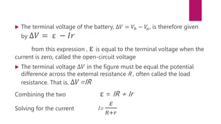
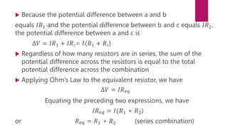
2) In a circuit with a battery and resistor, the battery's terminal voltage is lower than its emf due to the battery's internal resistance. Terminal voltage equals emf minus the voltage drop across the internal resistance due to current flow.
3) For resistors in series, the total resistance is equal to the sum of the individual resistances. Current flow is the same through all elements, so the total potential difference across the combination of resistors is equal to the sum of the individual potential


![Human Reproduction [ Reproductive System ] Notes @irfanullah_mehar Irfanullah...](https://cdn.slidesharecdn.com/ss_thumbnails/humanreproductionreproductivesystemnotesirfanullahmeharirfanullahmeharjanantantra-260111172350-56e85778-thumbnail.jpg?width=640&height=640&fit=bounds)


