SlideShare a Scribd company logo
1 of 2
Download to read offline
CIP 10 - Strength of In-Place Concrete
 WHAT is the Strengthof In-Place Concrete?
Concrete structures are designed to carry dead and
live loads during construction and in service. Samples
of concrete are obtained during construction and stan-
dard ASTM procedures are used to measure the po-                A                              B
tential strength of the concrete as delivered. Cylinders
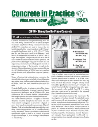
are molded and cured at 60 to 80°F (17 to 27°C) for                                            A - Penetration
one day and then moist cured in the laboratory until              C
                                                                                                   Resistance Test
broken in compression, normally at an age of 7 and 28                                              (ASTM C 803)
days. The in-place strength of concrete will not be
equivalent to that measured on standard cylinders. Job                                         B - Rebound Test
practices for handling, placing, consolidation, and cur-                                           (ASTM C 805)
ing concrete in structures are relied upon to provide an
adequate percentage of that potential strength in the                                          C - Core Test
                                                                                                   (ASTM C 42)
structure. Structural design principles recognize this and
the ACI Building Code, ACI 318, has a process of as-
suring the structural safety of the concrete construc-
                                                                      WHY Measure In-Place Strength?
tion.                                                         Tests of in-place concrete may be needed when stan-
Means of measuring, estimating or comparing the               dard cylinder strengths are low and not in compliance
strength of in-place concrete include: rebound hammer,        with the specification as outlined in ACI 318. How-
penetration probe, pullouts, cast-in-place cylinders, tests   ever, do not investigate in-place without first checking
of drilled cores, and load tests of the structural ele-       to be sure that: the concrete strengths actually failed
ment.                                                         to meet the specification provisions, low strengths are
                                                              not attributable to faulty testing practices, or the speci-
Cores drilled from the structure are one of the means
                                                              fied strength is really needed. (See CIP 9) In many
of evaluating whether the structural capacity of a con-
                                                              cases, the concrete can be accepted for the intended
crete member is adequate and ACI 318 provides some
                                                              use without in-place strength testing.
guidance on this evaluation. Drilled cores test lower
than properly made and tested standard molded 6 x 12          There are many other situations that may require the
inch (150 x 300-mm) cylinders. This applies to all formed     investigation of in-place strength. These include: shore
structural concrete. Exceptions may occur for cores           and form removal, post-tensioning, or early load appli-
from concrete cast against an absorptive subgrade or          cation; investigation of damage due to freezing, fire,
cores from lean, low strength mass concrete. The ACI          or adverse curing exposure; evaluation of older struc-
Building Code recognizes that under current design prac-      tures; and when a lower design strength concrete is
tices, concrete construction can be considered struc-         placed in a member by mistake. When cores or other
turally adequate if the average of three cores from the       in-place tests fail to assure structural adequacy, addi-
questionable region is equal to or exceeds 85 percent         tional curing of the structure may provide the neces-
of specified strength, ƒ´c with no single core less than      sary strength. This is particularly possible with con-
75 percent of ƒ´c.                                            crete containing slow strength-gaining cement, fly ash,
                                                              or slag.
b. Accurate measurement of the exposed length of the
    HOW to Investigate In-Place Strength?                        probe is required;
If only one set of cylinders is low, often the question      c. Probes should be spaced at least 7 in. apart and not
can be settled by comparing rebound hammer or probe              be close to the edge of the concrete;
results on concrete in areas represented by acceptable       d. Probes not firmly embedded in the concrete should
cylinder results. Where the possibility of low strength          be rejected; and
is such that large portions need to be investigated, a
                                                             e. Develop a strength calibration curve for the materi-
well-organized study will be needed. Establish a grid
                                                                 als and conditions under investigation.
and obtain systematic readings including good and ques-
tionable areas. Tabulate the hammer or probe read-           Rebound Hammer, ASTM C 805 - Observe these
ings. If areas appear to be low, drill cores from both       precautions:
low and high areas. If the cores confirm the hammer          a. Wet all surfaces for several hours or overnight be-
or probe results, the need for extensive core tests is           cause drying affects rebound number;
greatly reduced.                                             b. Don’t compare readings on concrete cast against
Core Strength, ASTM C 42 - If core drilling is nec-              different form materials, concrete of varying mois-
essary observe these precautions:                                ture content, readings from different impact direc-
a. Test a minimum of 3 cores for each section of ques-           tions, on members of different mass, or results us-
    tionable concrete;                                           ing different hammers;
b. Obtain 31/2 in. (85 mm) minimum diameter cores.           c. Don’t grind off the surface unless it is soft, finished
    Obtain larger cores for concrete with over 1 in. (25.0       or textured;
    mm) size aggregate;                                      d. Test structural slabs from the bottom; and
c. Try to obtain a length at least 11/2 times the diam-      e. Do not test frozen concrete.
    eter (L/D ratio);                                        Advance Planning - When it is known in advance
d. Trim to remove steel provided the minimum 11/2 L/         that in-place testing is required, such as for shore and
    D ratio can be maintained;                               form removal, other methods can be considered such
e. Trim ends square with an automatic feed diamond           as: cast-in-place, push-out cylinders and pullout strength
    saw;                                                     measuring techniques covered by ASTM C 873 and C
                                                             900.
f. When testing, keep cap thickness under 1/8 in. (3
    mm);
g. Use high strength capping material; neoprene pad
    caps should not be used;
h. Check planeness of caps and bearing blocks;                                      References
i. Do not drill cores from the top layers of columns,        1. In-Place Methods to Estimate Concrete Strength, ACI 228.1R,
                                                                American Concrete Institute, Farmington Hills, MI.
    slabs, walls, or footings, which will be 10 to 20 per-
                                                             2. Nondestructive Tests, V.M. Malhotra, Chapter 30 in ASTM
    cent weaker than cores from the mid or lower por-
                                                                STP 169C, American Society for Testing and Materials, West
    tions; and                                                  Conshohocken, PA.
j. Test cores after drying for 7 days if the structure is    3. Guide to Nondestructive Testing of Concrete, G.I. Crawford,
    dry in service; otherwise soak cores 40 hours prior         Report FHWA-SA-97-105, Sept. 1997, Federal Highway Ad-
    to testing. Review the recommendations for condi-           ministration, Washington, DC.
    tioning cores in current versions of ACI 318 and         4. In-Place Strength Evaluation - A Recommended Practice,
                                                                NRMCA Publication 133, NRMCA, Silver Spring, MD.
    ASTM C 42.
                                                             5. Understanding Concrete Core Testing, Bruce A. Suprenant,
Probe Penetration Resistance, ASTM C 803 -                      NRMCA Publication 185, NRMCA, Silver Spring, MD.
Probes driven into concrete can be used to study varia-      6. ASTM C 31, C 39, C 42, C 805, C 803, C 873, C 900, ASTM
tions in concrete quality:                                      Book of Standards, Vol. 04.02, American Society for Testing
                                                                and Materials, West Conshohocken, PA
a. Different size probes or a change in driving force
                                                             7. Building Code Requirements for Structural Concrete, ACI 318,
    may be necessary for large differences in strength          American Concrete Institute, Farmington Hills, MI.
    or unit weight;
                                                                                                        1982, 1989 AND 2000

More Related Content

What's hot

Retrofitting Of Reinforced Concrete Column by Steel Jacketing
Retrofitting Of Reinforced Concrete Column by Steel JacketingRetrofitting Of Reinforced Concrete Column by Steel Jacketing
Retrofitting Of Reinforced Concrete Column by Steel Jacketing
IJERA Editor
 

What's hot (18)

Retrofitting Of Reinforced Concrete Column by Steel Jacketing
Retrofitting Of Reinforced Concrete Column by Steel JacketingRetrofitting Of Reinforced Concrete Column by Steel Jacketing
Retrofitting Of Reinforced Concrete Column by Steel Jacketing
 
Retrofitting and Strengthening of Damaged Reinforced Concrete Columns Using S...
Retrofitting and Strengthening of Damaged Reinforced Concrete Columns Using S...Retrofitting and Strengthening of Damaged Reinforced Concrete Columns Using S...
Retrofitting and Strengthening of Damaged Reinforced Concrete Columns Using S...
 
Pre-test Seismic Evaluation of Drywall Partition Walls Integrated with a Timb...
Pre-test Seismic Evaluation of Drywall Partition Walls Integrated with a Timb...Pre-test Seismic Evaluation of Drywall Partition Walls Integrated with a Timb...
Pre-test Seismic Evaluation of Drywall Partition Walls Integrated with a Timb...
 
Strengthening of rc beams using prestressed fiber reinforced polymers – a review
Strengthening of rc beams using prestressed fiber reinforced polymers – a reviewStrengthening of rc beams using prestressed fiber reinforced polymers – a review
Strengthening of rc beams using prestressed fiber reinforced polymers – a review
 
4403 r 04
4403 r 044403 r 04
4403 r 04
 
Weathering of Rocks: Laboratory Test
Weathering of Rocks: Laboratory TestWeathering of Rocks: Laboratory Test
Weathering of Rocks: Laboratory Test
 
STRENGTHENING OF RC BEAMS USING FRP SHEET
STRENGTHENING OF RC BEAMS USING FRP SHEETSTRENGTHENING OF RC BEAMS USING FRP SHEET
STRENGTHENING OF RC BEAMS USING FRP SHEET
 
aci 211_1_91.pdf
aci 211_1_91.pdfaci 211_1_91.pdf
aci 211_1_91.pdf
 
J012637178
J012637178J012637178
J012637178
 
V01226139142
V01226139142V01226139142
V01226139142
 
A Review On Strengthening Of RCC Square Columns with Reinforced Concrete Jack...
A Review On Strengthening Of RCC Square Columns with Reinforced Concrete Jack...A Review On Strengthening Of RCC Square Columns with Reinforced Concrete Jack...
A Review On Strengthening Of RCC Square Columns with Reinforced Concrete Jack...
 
CE 72.52 - Lecture 8b - Retrofitting of RC Members
CE 72.52 - Lecture 8b - Retrofitting of RC MembersCE 72.52 - Lecture 8b - Retrofitting of RC Members
CE 72.52 - Lecture 8b - Retrofitting of RC Members
 
A Comparative Study for Seismic Performance of RC Moment Resisting Frame with...
A Comparative Study for Seismic Performance of RC Moment Resisting Frame with...A Comparative Study for Seismic Performance of RC Moment Resisting Frame with...
A Comparative Study for Seismic Performance of RC Moment Resisting Frame with...
 
Capacity of strengthened Reinforced concrete columns
Capacity of strengthened Reinforced concrete columnsCapacity of strengthened Reinforced concrete columns
Capacity of strengthened Reinforced concrete columns
 
Finite element analysis of jacketed reinforced concrete column subjected to u...
Finite element analysis of jacketed reinforced concrete column subjected to u...Finite element analysis of jacketed reinforced concrete column subjected to u...
Finite element analysis of jacketed reinforced concrete column subjected to u...
 
A STUDY OF STEEL, BAMBOO AND RATTAN AS REINFORCING BARS
A STUDY OF STEEL, BAMBOO AND RATTAN AS REINFORCING BARSA STUDY OF STEEL, BAMBOO AND RATTAN AS REINFORCING BARS
A STUDY OF STEEL, BAMBOO AND RATTAN AS REINFORCING BARS
 
Comparative Study on Flexural Strength of M-40 Grade with Lapping of Bars
Comparative Study on Flexural Strength of M-40 Grade with Lapping of BarsComparative Study on Flexural Strength of M-40 Grade with Lapping of Bars
Comparative Study on Flexural Strength of M-40 Grade with Lapping of Bars
 
Seismic retrofitting using fiber reinforced polymer (frp
Seismic retrofitting using fiber reinforced polymer (frpSeismic retrofitting using fiber reinforced polymer (frp
Seismic retrofitting using fiber reinforced polymer (frp
 

Viewers also liked (9)

Straight from the heart Testimonials
Straight from the heart TestimonialsStraight from the heart Testimonials
Straight from the heart Testimonials
 
04
0404
04
 
Week6 spring2013-part2
Week6 spring2013-part2Week6 spring2013-part2
Week6 spring2013-part2
 
Instructivo distancia20132
Instructivo distancia20132Instructivo distancia20132
Instructivo distancia20132
 
Misterio
MisterioMisterio
Misterio
 
Nishara fb collection
Nishara fb collectionNishara fb collection
Nishara fb collection
 
Aula de inglês 41 uso de too e either
Aula de inglês 41   uso de too e eitherAula de inglês 41   uso de too e either
Aula de inglês 41 uso de too e either
 
地域と研究者・論文のコラボで実現する、地域のための課題解決エンジン
地域と研究者・論文のコラボで実現する、地域のための課題解決エンジン地域と研究者・論文のコラボで実現する、地域のための課題解決エンジン
地域と研究者・論文のコラボで実現する、地域のための課題解決エンジン
 
Bibliografía
BibliografíaBibliografía
Bibliografía
 

Similar to Cip+10.unlocked

Evaluation of concrete spall repairs by pullout test
Evaluation of concrete spall repairs by pullout testEvaluation of concrete spall repairs by pullout test
Evaluation of concrete spall repairs by pullout test
frank collins
 
Non destructive tests on Concrete.pptx
Non destructive tests on Concrete.pptxNon destructive tests on Concrete.pptx
Non destructive tests on Concrete.pptx
ReigerRoyal
 

Similar to Cip+10.unlocked (20)

REBOUND Hammer Test
REBOUND Hammer Test REBOUND Hammer Test
REBOUND Hammer Test
 
Structural Performance of Jacketing in Reinforced Concrete Columns: A Brief S...
Structural Performance of Jacketing in Reinforced Concrete Columns: A Brief S...Structural Performance of Jacketing in Reinforced Concrete Columns: A Brief S...
Structural Performance of Jacketing in Reinforced Concrete Columns: A Brief S...
 
The Study of Flexural and Ultimate Behavior of Ferrocement Lightweight Beam b...
The Study of Flexural and Ultimate Behavior of Ferrocement Lightweight Beam b...The Study of Flexural and Ultimate Behavior of Ferrocement Lightweight Beam b...
The Study of Flexural and Ultimate Behavior of Ferrocement Lightweight Beam b...
 
Railway over bridge
Railway over bridgeRailway over bridge
Railway over bridge
 
Sub.ass.2
Sub.ass.2Sub.ass.2
Sub.ass.2
 
Experimental investigation of reinforcement couplers as replacement of bent-bar
Experimental investigation of reinforcement couplers as replacement of bent-barExperimental investigation of reinforcement couplers as replacement of bent-bar
Experimental investigation of reinforcement couplers as replacement of bent-bar
 
Cyclic Response of Reinforced Concrete Moment Resisting Beams Repaired with E...
Cyclic Response of Reinforced Concrete Moment Resisting Beams Repaired with E...Cyclic Response of Reinforced Concrete Moment Resisting Beams Repaired with E...
Cyclic Response of Reinforced Concrete Moment Resisting Beams Repaired with E...
 
Cyclic Response of Reinforced Concrete Moment Resisting Beams Repaired with E...
Cyclic Response of Reinforced Concrete Moment Resisting Beams Repaired with E...Cyclic Response of Reinforced Concrete Moment Resisting Beams Repaired with E...
Cyclic Response of Reinforced Concrete Moment Resisting Beams Repaired with E...
 
Evaluation of concrete spall repairs by pullout test
Evaluation of concrete spall repairs by pullout testEvaluation of concrete spall repairs by pullout test
Evaluation of concrete spall repairs by pullout test
 
Condition Assessment and Evaluation of Concrete Structures by Advanced Non-de...
Condition Assessment and Evaluation of Concrete Structures by Advanced Non-de...Condition Assessment and Evaluation of Concrete Structures by Advanced Non-de...
Condition Assessment and Evaluation of Concrete Structures by Advanced Non-de...
 
Concrete
ConcreteConcrete
Concrete
 
Experimental Investigation on Steel Concrete Composite Floor Slab
Experimental Investigation on Steel Concrete Composite Floor SlabExperimental Investigation on Steel Concrete Composite Floor Slab
Experimental Investigation on Steel Concrete Composite Floor Slab
 
Experimental Investigation on Effect of Curtailed reinforcement in R.C beams
Experimental Investigation on Effect of Curtailed reinforcement in R.C beamsExperimental Investigation on Effect of Curtailed reinforcement in R.C beams
Experimental Investigation on Effect of Curtailed reinforcement in R.C beams
 
Non destructive tests on Concrete.pptx
Non destructive tests on Concrete.pptxNon destructive tests on Concrete.pptx
Non destructive tests on Concrete.pptx
 
IRJET- Experimental Evaluation of Strength of Damaged RCC Beam Repaired us...
IRJET- 	  Experimental Evaluation of Strength of Damaged RCC Beam Repaired us...IRJET- 	  Experimental Evaluation of Strength of Damaged RCC Beam Repaired us...
IRJET- Experimental Evaluation of Strength of Damaged RCC Beam Repaired us...
 
SEMI DESTRUCTIVE Test On Concrete _by Imran B K
SEMI DESTRUCTIVE  Test On Concrete _by Imran B KSEMI DESTRUCTIVE  Test On Concrete _by Imran B K
SEMI DESTRUCTIVE Test On Concrete _by Imran B K
 
Testing of hardened concrete
Testing of hardened concreteTesting of hardened concrete
Testing of hardened concrete
 
CRITICAL REVIEW ON MECHANICAL ANCHORAGE AS REPLACEMENT OF BENT BAR
CRITICAL REVIEW ON MECHANICAL ANCHORAGE AS REPLACEMENT OF BENT BARCRITICAL REVIEW ON MECHANICAL ANCHORAGE AS REPLACEMENT OF BENT BAR
CRITICAL REVIEW ON MECHANICAL ANCHORAGE AS REPLACEMENT OF BENT BAR
 
Aci structural concrete_design
Aci structural concrete_designAci structural concrete_design
Aci structural concrete_design
 
presentation
presentationpresentation
presentation
 

Cip+10.unlocked

  • 1. CIP 10 - Strength of In-Place Concrete WHAT is the Strengthof In-Place Concrete? Concrete structures are designed to carry dead and live loads during construction and in service. Samples of concrete are obtained during construction and stan- dard ASTM procedures are used to measure the po- A B tential strength of the concrete as delivered. Cylinders are molded and cured at 60 to 80°F (17 to 27°C) for A - Penetration one day and then moist cured in the laboratory until C Resistance Test broken in compression, normally at an age of 7 and 28 (ASTM C 803) days. The in-place strength of concrete will not be equivalent to that measured on standard cylinders. Job B - Rebound Test practices for handling, placing, consolidation, and cur- (ASTM C 805) ing concrete in structures are relied upon to provide an adequate percentage of that potential strength in the C - Core Test (ASTM C 42) structure. Structural design principles recognize this and the ACI Building Code, ACI 318, has a process of as- suring the structural safety of the concrete construc- WHY Measure In-Place Strength? tion. Tests of in-place concrete may be needed when stan- Means of measuring, estimating or comparing the dard cylinder strengths are low and not in compliance strength of in-place concrete include: rebound hammer, with the specification as outlined in ACI 318. How- penetration probe, pullouts, cast-in-place cylinders, tests ever, do not investigate in-place without first checking of drilled cores, and load tests of the structural ele- to be sure that: the concrete strengths actually failed ment. to meet the specification provisions, low strengths are not attributable to faulty testing practices, or the speci- Cores drilled from the structure are one of the means fied strength is really needed. (See CIP 9) In many of evaluating whether the structural capacity of a con- cases, the concrete can be accepted for the intended crete member is adequate and ACI 318 provides some use without in-place strength testing. guidance on this evaluation. Drilled cores test lower than properly made and tested standard molded 6 x 12 There are many other situations that may require the inch (150 x 300-mm) cylinders. This applies to all formed investigation of in-place strength. These include: shore structural concrete. Exceptions may occur for cores and form removal, post-tensioning, or early load appli- from concrete cast against an absorptive subgrade or cation; investigation of damage due to freezing, fire, cores from lean, low strength mass concrete. The ACI or adverse curing exposure; evaluation of older struc- Building Code recognizes that under current design prac- tures; and when a lower design strength concrete is tices, concrete construction can be considered struc- placed in a member by mistake. When cores or other turally adequate if the average of three cores from the in-place tests fail to assure structural adequacy, addi- questionable region is equal to or exceeds 85 percent tional curing of the structure may provide the neces- of specified strength, ƒ´c with no single core less than sary strength. This is particularly possible with con- 75 percent of ƒ´c. crete containing slow strength-gaining cement, fly ash, or slag.
  • 2. b. Accurate measurement of the exposed length of the HOW to Investigate In-Place Strength? probe is required; If only one set of cylinders is low, often the question c. Probes should be spaced at least 7 in. apart and not can be settled by comparing rebound hammer or probe be close to the edge of the concrete; results on concrete in areas represented by acceptable d. Probes not firmly embedded in the concrete should cylinder results. Where the possibility of low strength be rejected; and is such that large portions need to be investigated, a e. Develop a strength calibration curve for the materi- well-organized study will be needed. Establish a grid als and conditions under investigation. and obtain systematic readings including good and ques- tionable areas. Tabulate the hammer or probe read- Rebound Hammer, ASTM C 805 - Observe these ings. If areas appear to be low, drill cores from both precautions: low and high areas. If the cores confirm the hammer a. Wet all surfaces for several hours or overnight be- or probe results, the need for extensive core tests is cause drying affects rebound number; greatly reduced. b. Don’t compare readings on concrete cast against Core Strength, ASTM C 42 - If core drilling is nec- different form materials, concrete of varying mois- essary observe these precautions: ture content, readings from different impact direc- a. Test a minimum of 3 cores for each section of ques- tions, on members of different mass, or results us- tionable concrete; ing different hammers; b. Obtain 31/2 in. (85 mm) minimum diameter cores. c. Don’t grind off the surface unless it is soft, finished Obtain larger cores for concrete with over 1 in. (25.0 or textured; mm) size aggregate; d. Test structural slabs from the bottom; and c. Try to obtain a length at least 11/2 times the diam- e. Do not test frozen concrete. eter (L/D ratio); Advance Planning - When it is known in advance d. Trim to remove steel provided the minimum 11/2 L/ that in-place testing is required, such as for shore and D ratio can be maintained; form removal, other methods can be considered such e. Trim ends square with an automatic feed diamond as: cast-in-place, push-out cylinders and pullout strength saw; measuring techniques covered by ASTM C 873 and C 900. f. When testing, keep cap thickness under 1/8 in. (3 mm); g. Use high strength capping material; neoprene pad caps should not be used; h. Check planeness of caps and bearing blocks; References i. Do not drill cores from the top layers of columns, 1. In-Place Methods to Estimate Concrete Strength, ACI 228.1R, American Concrete Institute, Farmington Hills, MI. slabs, walls, or footings, which will be 10 to 20 per- 2. Nondestructive Tests, V.M. Malhotra, Chapter 30 in ASTM cent weaker than cores from the mid or lower por- STP 169C, American Society for Testing and Materials, West tions; and Conshohocken, PA. j. Test cores after drying for 7 days if the structure is 3. Guide to Nondestructive Testing of Concrete, G.I. Crawford, dry in service; otherwise soak cores 40 hours prior Report FHWA-SA-97-105, Sept. 1997, Federal Highway Ad- to testing. Review the recommendations for condi- ministration, Washington, DC. tioning cores in current versions of ACI 318 and 4. In-Place Strength Evaluation - A Recommended Practice, NRMCA Publication 133, NRMCA, Silver Spring, MD. ASTM C 42. 5. Understanding Concrete Core Testing, Bruce A. Suprenant, Probe Penetration Resistance, ASTM C 803 - NRMCA Publication 185, NRMCA, Silver Spring, MD. Probes driven into concrete can be used to study varia- 6. ASTM C 31, C 39, C 42, C 805, C 803, C 873, C 900, ASTM tions in concrete quality: Book of Standards, Vol. 04.02, American Society for Testing and Materials, West Conshohocken, PA a. Different size probes or a change in driving force 7. Building Code Requirements for Structural Concrete, ACI 318, may be necessary for large differences in strength American Concrete Institute, Farmington Hills, MI. or unit weight; 1982, 1989 AND 2000