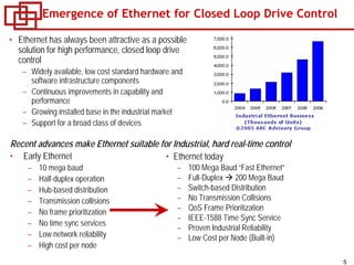
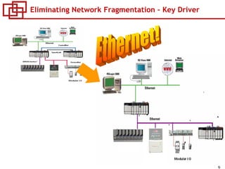
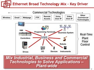
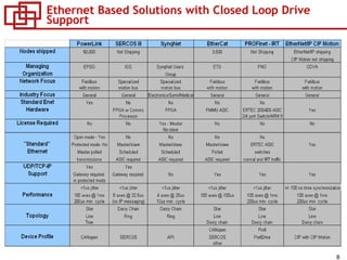
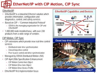
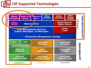
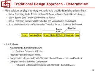
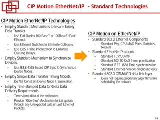
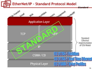
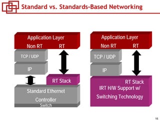
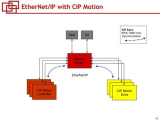
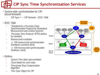
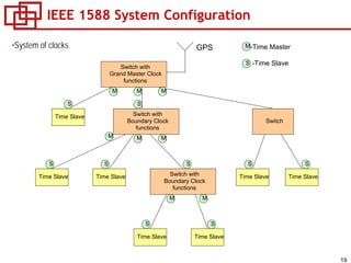
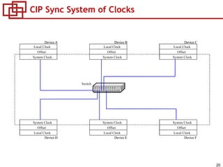
2. 2
High-Performance Closed Loop Drive Control
Using EtherNet/IP
• This session will discuss why Industrial Ethernet is emerging as the network
technology of choice for control of high performance drives.
• EtherNet/IP with CIP Sync and CIP Motion will be presented as an example
of an Ethernet solution which provides high performance drive control, and
peer-to-peer motion synchronization.
1. Drive interface technology overview1. Drive interface technology overview
2. Digital Motion Network Evolution2. Digital Motion Network Evolution
3. Emergence of EtherNet for Drive Control3. Emergence of EtherNet for Drive Control
4. EtherNet/IP with CIP Motion Overview4. EtherNet/IP with CIP Motion Overview
3. 3
Closed Loop Drive Control Interface Options
• Analog
– First motion interface, has a long history
– Wide range of interoperable controls and drives from
multiple vendors
– Significant disadvantages
• 12 discrete low level noise sensitive signals for
drive command and feedback
• Limited feedback resolution
• Lack of drive/motor configuration and diagnostics
communications
• Digital network
– First generation introduced in the early 1990’s
• Optimized for closed loop drive control
– Significant advantages
• Replacement of discrete signals with a single
network connection
• Distributed control loops for higher performance
• Support for distributed, high resolution, multi-turn
absolute feedback
• Drive/motor configuration and diagnostic
communications
– Disadvantages
• Difficulty integrating products from multiple
vendors – proprietary, many standards
• A separate network is typically required for field
bus device support
4. 4
Digital Motion Network Evolution
• There are a number of open and proprietary “first
generation” motion network solutions
– SERCOS interface was one of the earliest motion control
network standards
• Development started in 1985, introduced in 1992,
• Defined by the IEC 61491 standard
• Has the broad vendor community support with over
60 vendors
• Optimized motion network
• Limitations of “first generation” motion networks have
driven the introduction of “second generation” motion
network standards
– Early solutions were based on FireWire (IEEE 1394)
• Adept
• Nyquist
• Ormec
– Recent introductions are based on Ethernet technology
• PowerLink
• PROFInet
• SERCOS III
• EtherNet/IP with CIP Motion
Ethernet
5. 5
• Ethernet today
– 100 Mega Baud “Fast Ethernet”
– Full-Duplex 200 Mega Baud
– Switch-based Distribution
– No Transmission Collisions
– QoS Frame Prioritization
– IEEE-1588 Time Sync Service
– Proven Industrial Reliability
– Low Cost per Node (Built-in)
• Ethernet has always been attractive as a possible
solution for high performance, closed loop drive
control
– Widely available, low cost standard hardware and
software infrastructure components
– Continuous improvements in capability and
performance
– Growing installed base in the industrial market
– Support for a broad class of devices
Emergence of Ethernet for Closed Loop Drive Control
Recent advances make Ethernet suitable for Industrial, hard real-time control
• Early Ethernet
– 10 mega baud
– Half-duplex operation
– Hub-based distribution
– Transmission collisions
– No frame prioritization
– No time sync services
– Low network reliability
– High cost per node
7. 7
Ethernet Broad Technology Mix – Key Driver
Commercial Technologies
Other
Commercial
Technologies
Remote
Access
Voice
Over IP
Video
Over IP
Wireless Email Webpage FTP
Controllers
Business SystemProgramming Terminals
HMI
Plant
Floor
Control
Drives I/O Devices Instruments
Robots
Real-Time
Mix Industrial, Business and Commercial
Technologies to Solve Applications –
Plant-wide
Mix Industrial, Business and Commercial
Technologies to Solve Applications –
Plant-wide
9. 9
EtherNet/IP with CIP Motion, CIP Sync
EtherNet/IP
• EtherNet/IP is a industrial Ethernet solution which
provides information, configuration and
diagnostics, control, and safety services
• Based on CIP – “Common Industrial Protocol”
– ODVA is the managing organization for CIP and
EtherNet/IP
• 1,000,000 node installed base, with over 230
products from a wide range of vendors
EtherNet/IP Capabilites and Devices
CIP Motion, CIP Sync
• CIP extensions which provide new real-time control
services
– Distributed node time synchronization
– Closed loop drive control
– Peer to peer control and drive synchronization
• Managed by ODVA Distributed Motion JSIG
• CIP April 2006 Specification Enhancement
– CIP Motion Control Axis Object
– CIP Motion Drive Axis Object
– CIP Motion Drive Device Profile
• EtherNet/IP first implementation focus
10. 10
What is CIP Motion™?
• CIP Common Extensions to Support Motion Control
– CIP Motion Axis Object
• Defines Attributes, Services, and Behavior of Motion Axis Instances associated
with a Motion Device, incl. drives, encoders, etc.
– Motion Control Axis Object
• Defines Attributes, Services, and Behavior of Motion Axis Instances associated
with a Motion Controller.
– CIP Motion Drive Device Profile
• Defines Dynamic Connection Data Structures
• Defines Motion Data Transfer Timing Model
• Includes CIP Sync Time Sync Object
– CIP Sync Time Sync Object defines the time synchronization services
• Capability Focus
– Closed and open loop control of a broad class of drives/motors
• From V/hz to closed loop vector to servos
• Open loop, and closed loop position, velocity, and torque
• Centralized and distributed planner (future) configurations
– Control peer-to-peer motion synchronization
• Gearing, camming, complex interpolation across distributed controllers
12. 12
Motion Network Requirements
• Synchronization Services
– Need a mechanism to synchronize all controller and drive nodes in the system to a
common time-base with sub-microsecond accuracy, node-to-node.
• Timely Data Transfer - determinism
– Need enough network bandwidth and packet-processing power to guarantee timely
exchange of cyclic data between multiple controller and drive nodes at sub-
millisecond update rates.
• Motion Control Device Profiles
– Need well-defined device profiles to provide a common interface to a wide variety of
contemporary motion control devices including drive profiles that span from simple
volts/hertz drives to vector controlled servo drives.
DATA
13. 13
Traditional Design Approach - Determinism
• Many solutions employ proprietary mechanisms to provide data delivery determinism
– Use of Proprietary Media Access Hardware/Software to Control Device Network Access.
– Use of Special EtherType or UDP Port Packet Format
– Use of Proprietary Gateways to Re-schedule non-Motion Packet Transmission
– Schedule Update Cycle into Transmission Time-slots for each Device on the Network.
Update
Cycle
SyncDrive 1 ControllerSync Drive 2 Drive 3ControllerDrive 3
Time Slot
• Implications
– Non-standard Ethernet Infrastructure
• Switches, Gateways, & Routers
– Proprietary Silicon in Device Nodes
– Compromised Interoperability with Standard Ethernet Devices, Tools, and Services.
– Complex Time Slot Schedule Configuration
• Scheduled Network is Incompatible with Standard Ethernet Devices
14. 14
CIP Motion EtherNet/IP – Standard Technologies
CIP Motion EtherNet/IP Technologies
• Employ Standard Mechanisms to Insure Timely
Data Transfer
– Use Full-Duplex 100-BaseT or 100BaseF “Fast”
Ethernet.
– Use Ethernet Switches to Eliminate Collisions.
– Use QoS Frame Prioritization to Eliminate
Queuing Delays
• Employ Standard Mechanism to Synchronize
Devices.
– Use IEEE-1588-based CIP Sync to Synchronize
Device Nodes.
• Employ Simple Data Transfer Timing Models.
– Do Not Constrain Device Node Transmission.
• Employ Time-stamped Data to Relax Data
Delivery Requirements.
– Time stamp data at the end nodes
– Provide “Ride-thru” Mechanism to Extrapolate
through any Unexpected Late or Lost Ethernet
Packets.
CIP Motion on EtherNet/IP
• Standard 802.3 Ethernet Components
– Standard Phy, CPU MAC Ports, Switches,
Routers
• Standard EtherNet Protocols
– Standard TCP/UDP/IP
– Standard 802.1Q QoS frame prioritization
– Standard IEEE-1588 Time synchronization
– Standard Ethernet network diagnostic tools
• Standard 802.3 CSMA/CD data link layer
– Does not require proprietary algorithms like
scheduling the network
15. 15
EtherNet/IP – Standard Protocol Model
Physical Layer
CSMA / CD
IP
TCP UDP
FTP SMTP HTTP VOIP DNS SNMP
File Transfer
Email
Web
Voice/Video
Management
Servers
Standard
Ethernet
Implementation
of OSI Model
Standard
CIP
EtherNet/IP
Application Layer
16. 16
Standard vs. Standards-Based Networking
Switch
Standard Ethernet
Controller
IP
TCP / UDP
RT Stack
Application Layer
Non RT RT
IRT H/W Support w/
Switching Technology
IP
TCP / UDP
RT Stack
Application Layer
Non RT RT
18. 18
CIP Sync Time Synchronization Services
• System-wide synchronization for CIP-
based Networks
– CIP Sync™ = CIP Network + IEEE-1588
• IEEE 1588
– “Standard for a Precision Clock
Synchronization Protocol for Networked
Measurement and Control Systems”
– “Precision Time Protocol” (PTP) defined
by standard.
– Nanosecond resolution
– +/- 100 nanosecond synchronization
(Hardware-assisted clock)
– +/- 100 microsecond synchronization
(Software clock)
• Defines
– System Time data representation
– Clock Model for each node
– Timestamp Step Compensation
Algorithm
– Time Sync Object for CIP
19. 19
IEEE 1588 System Configuration
Switch with
Grand Master Clock
functions
GPS M
S
-Time Master
-Time Slave
•System of clocks
Switch with
Boundary Clock
functions
Switch
Time Slave
Time Slave
Switch with
Boundary Clock
functions
Time Slave Time Slave Time Slave
S
M MM
S S
S
MMM
SS S
M
SS
M
Time Slave Time Slave
20. 20
CIP Sync System of Clocks
Device A Device B Device C
Device D Device F
Local Time
Offset
System Time
Local Time
Offset
System Time
Local Time
Offset
System Time
System Time
Offset
Local Time
Device E
System Time
Offset
Local Time
System Time
Offset
Local Time
Device A Device B Device C
Device D Device F
Local Time
Offset
System Time
Local Time
Offset
System Time
Local Time
Offset
System Time
System Time
Offset
Local Time
Device E
System Time
Offset
Local Time
System Time
Offset
Local Time
Device A Device BDevice B Device CDevice C
Device DDevice D Device FDevice F
Local Time
Offset
System Time
Local Clock
Offset
System Clock
Local Time
Offset
System Time
Local Clock
Offset
System Clock
Local Time
Offset
System Time
Local Clock
Offset
System Clock
System Time
Offset
Local Time
System Clock
Offset
Local Clock
Device E
System Time
Offset
Local Time
Device EDevice E
System Time
Offset
Local Time
System Clock
Offset
Local Clock
System Time
Offset
Local Time
System Clock
Offset
Local Clock
Switch
21. 21
Quality of Service (QoS)
• CIP Sync implements Quality of Service
– 802.1Q tagged frames on Ethernet
• Insures timely delivery of high priority traffic
Ethernet
Switch
Distributed I/O Messages
CIP Motion™ Drive message
Other Devices Messages
1588 PTP Messages
Traffic Type Priority
Time Sync 7 (Highest)
Motion 6
I/O 5
Other 4 (Lowest)
23. 23
CIP Motion I/O Connection
– Based on Standard CIP Bi-directional Class 1 Implicit Point-to-Point Connection.
– Innovative Drive Connection Data Structure Supports 3 Prioritized Data Channels.
24. 24
Flexible Connection Data Structures
– CIP Motion Connection Data Structure
and Data Blocks can Change in both
Size and Content.
– Data Format described in Connection
Headers.
– Single Structure supports Multiple Axis
Instances.
– Event Channel supports Multiple Events
per Axis.
– Flexible Service Channel per Axis.
Controller Update Period
Controller Time Offset
Controller Time Stamp
25. 25
Flexible Connection Data Structures
Controls the state of the associated drive communications node.
• Remote Control
0 – under control of local drive interface
1 - CIP Motion Controller
• Sync Control
0 - Asynchronous Operation
1 – Synchronous Operation
• Controller Data Valid
Allows the drive to check for valid data during initialization
• Node Fault Reset
Request for CIP Motion drive to perform a reset of the
communications
0 = (Reserved)
1 = (Reserved)
2 = Fixed Controller-to-Device Connection
3 = Fixed Device-to-Controller Connection
4 = (Reserved)
5 = (Reserved)
6 = Variable Controller-to-Device Connection
7 = Variable Device-to-Controller Connection
8-15 = Reserved.
26. 26
Drive Connection Timing Model
Input Traffic Non-motion Traffic Output Traffic
Coarse Update Drive Update Period
Drive Timer Events
Controller Timer Events
Drive Interrupt Service
Drive-to-Control Connection (Input)
Control-to-Drive Connection (Output)
Controller Task
Actual Position
Cmd Position
Coarse Update Period (1 msec)
250 µsec
Measure
Actuate
Calculate
Communicate
Motion PlannerMotion Planner
Communicate
Motion Task
Phase Offset
27. 27
Topology support
• Star topology
– Supports removal/insertion of drives
without impacting the operation of other
drives on the network
– Supports on-line addition of new drives
• Complements dynamic telegram
configuration
– Effective when drives are centrally located
near the switch
• Daisy chain topology
– Simplifies interconnect wiring between
distributed devices
– Effective when devices are not located
near the switch
28. 28
IP Addressing Options – ADR Support
• Isolated network configuration
– 3 digit thumbwheel switch on the drive can be used to set the last octet of the drive’s IP
address (192.168.xxx)
– Facilitates easy setup and identification of the drive IP address
• No need for a DHCP/BOOTP server
– Can use a unmanaged switch
– Facilitates easy replacement and reconfiguration of a failed drive
• Set new drive switch setting to match the setting of the drive being replaced
• Automatic detection and reconfiguration of the drive (ADR support)
• Integrated network configuration
– 3 digit thumbwheel switch on the drive is set from 255-999, which initiates use of a
DHCP/BOOTP server for IP address assignment
– Facilitates easy replacement and reconfiguration of a failed drive (requires use of a
DHCP server/switch with option 82 support)
29. 29
Centralized and Distributed Architectures
• Centralized trajectory planner
– Centralized control with trajectory planner
support for a group of drives
– Servo loop closure typically located in the
drive but can be located in the centralized
control
• Distributed trajectory planner
– Trajectory planner located in the drive
– Servo loop closure located in the drive
• Control of simple of non-synchronized axes
– Control of simple process axes or machine
configuration axes
– Reduces controller and network overhead
while retaining all the configuration and
programming advantages of a centralized
planner
– Enables drive support on networks that do
not support time synchronization services
• High performance gearing and PCAMing
– Local gearing and PCAMing trajectory
control for fast updates and ultra-high
performance
Drive based
Trajectory Planner
Controller based
Trajectory Planner
30. 30
Integrated Drive Safety
• Single network connection for drive
command, configuration, status, and
safety support
• EtherNet/IP safety channel supports drive
safety configuration and interlocking
– Eliminates the need for a discrete safety
interface
– Eliminates the need for a separate network
or local connection for drive safety
configuration
– Simplifies integration and commissioning
• Integration with other EtherNet/IP safety
devices
Integral dual channel monitoring
Safe operational stop (cat0,1,2)
Zero speed monitoring
Safe reduced speed
Safe maximum speed
Enabling switch control
Door monitoring and control
Safe direction monitoring
Safe jog
Safe homing
Safe position monitoring
Integral dual channel monitoring
Safe operational stop (cat0,1,2)
Zero speed monitoring
Safe reduced speed
Safe maximum speed
Enabling switch control
Door monitoring and control
Safe direction monitoring
Safe jog
Safe homing
Safe position monitoring
31. 31
CIP Motion – Comprehensive Technology
• Wide Range of Drive Types and configurations
• Control-to-controller connectivity
• Multi-vendor Drive/Motor/Feedback Interoperability
• Simple Network Connection Startup
• Modern, comprehensive Drive Profile
EtherN
et/IP
w
ith
C
IP
M
otion
O
therM
otion
N
etw
orks
Standard, unmodified IEEE 802.3 Ethernet data link and physical layer
Uses standard TCP/IP and UDP transport and network
(Not All)
Use of standard, commercially available Ethernet hardware, switches, routers
Integration of non-automation devices on the same network segment
Integration of field devices, I/O, drives, and motion on same network
(Not All)
Simple, scalable network configuration - no schedule required
Compatible with all standard Ethernet topologies
(Not All)
Run time configuration changes
Support for real time (<1ms), multi-axis synchronized motion control
100 Axes with 1 ms Update – 200nS Clock
Synchronization
100 Axes with 1 ms Update100 Axes with 1 ms Update –– 200nS Clock200nS Clock
SynchronizationSynchronization