Download to read offline
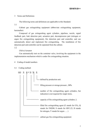
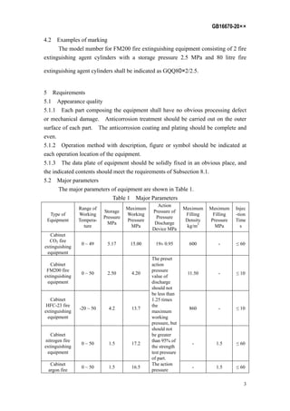
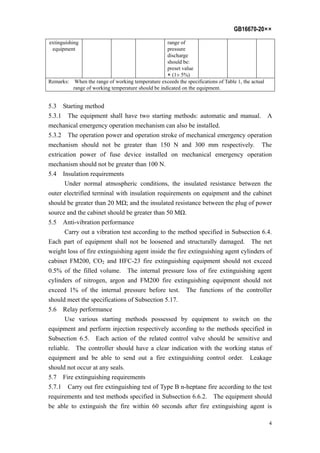


This document is the National Standard of the People's Republic of China GB16670-20XX replacing GB 16670-1996 regarding cabinet gas fire extinguishing equipment. It specifies performance requirements, test methods, inspection regulations, marking, packaging, transportation, storage and operation manual requirements. The major changes from the previous standard include revisions to chapters and appendices, increased parameters for different fire extinguishing equipment types, and additional test method and equipment requirements. It was proposed by the Ministry of Public Security and managed by the National Technical Committee for Fire Protection Standardization.


