
Downloaded 16 times
![Proline Prosonic Flow B 200
[ft/s] [m/s]
1600 500
1450 450
T
1300 400
1150 350
1000 300
850 250
700 200
0 10 20 30 40 50 60 70 80 90 100 [%]
A0016160
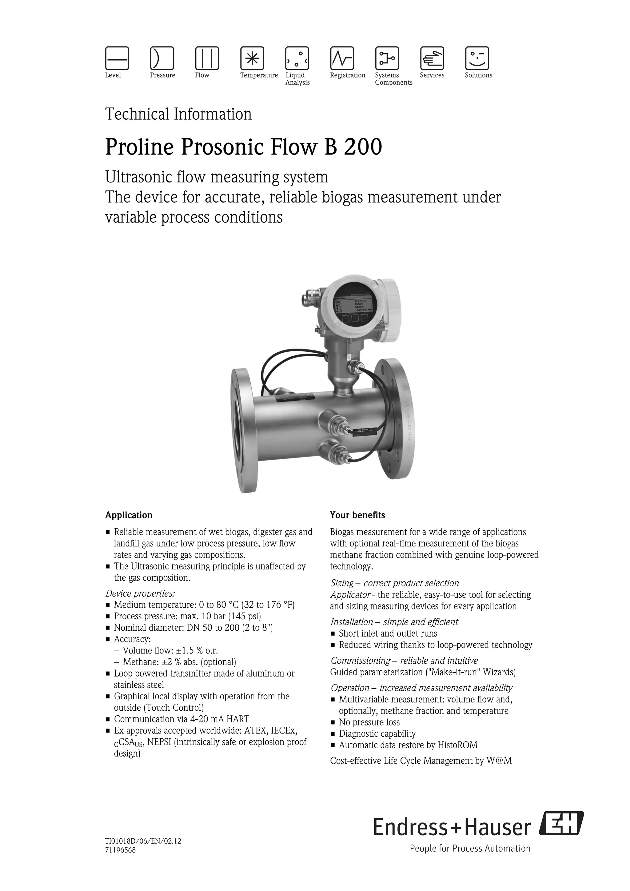
å1 Calculation of the methane fraction [%] based on the sound velocity [m/s (ft/s)] and a temperature T of 40 °C
(104 °F), for example
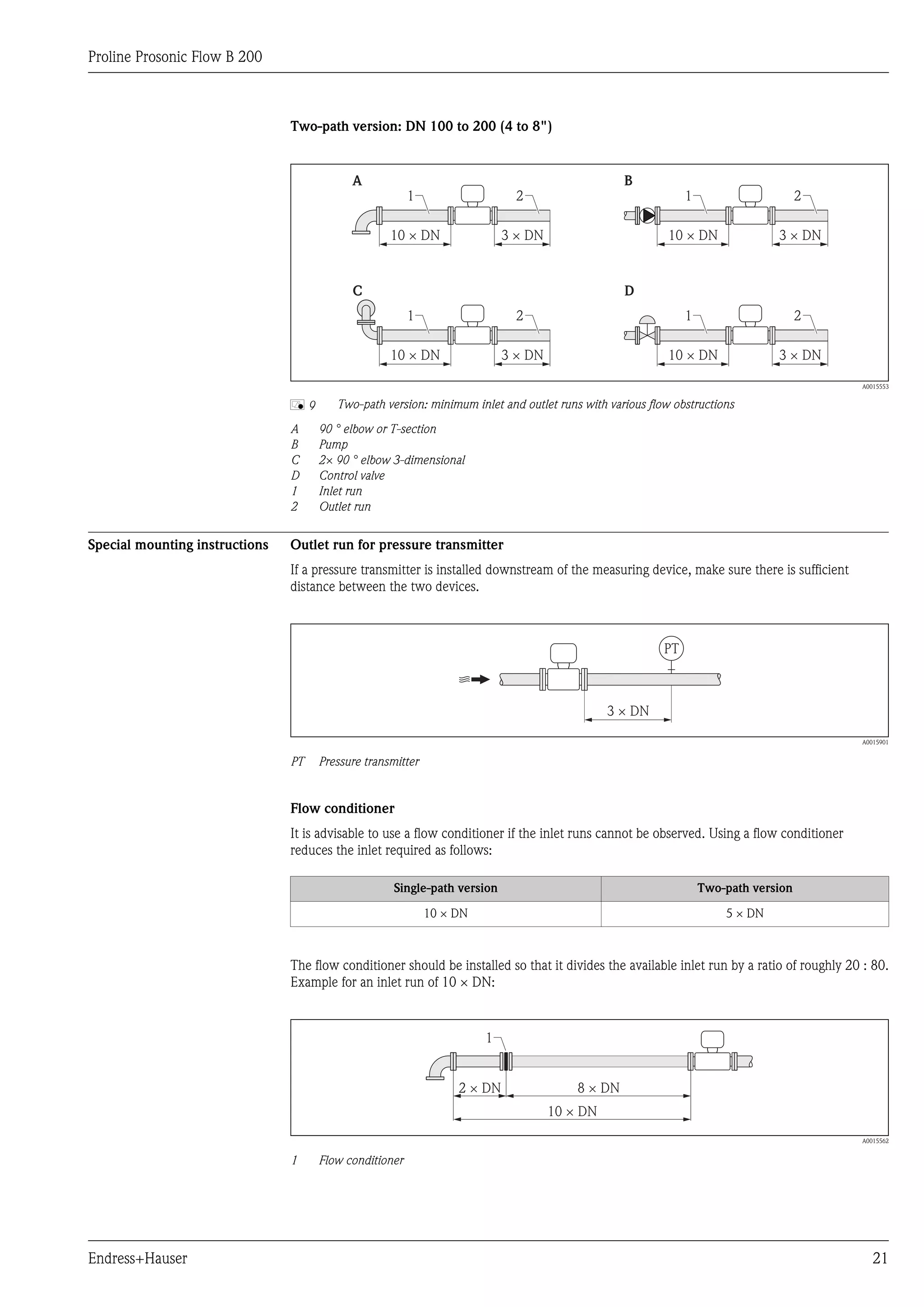
Measuring system The device consists of a transmitter and a sensor.
One device version is available: compact version, transmitter and sensor form a mechanical unit.
Transmitter
Prosonic Flow 200 Materials:
• Stainless steel 1.4404/316L
• Aluminum coated AlSi10Mg
Configuration:
• External operation via four-line, illuminated local display with touch control
and guided menus ("Make-it-run" wizards) for applications
A0013471 • Via operating tools (e.g. FieldCare)
Sensor
Prosonic Flow B • Designed exclusively to measure:
– Biogas
Single-path version: DN 50 (2"), – Coal seam gas
DN 80 (3") – Air
– Methane
– Nitrogen
– Gas with a very high methane fraction
• Range of nominal diameter: DN 50 to 200 (2 to 8")
• Materials:
– Sensor:
Stainless steel 1.4404/316L, cold worked
Stainless steel 1.4435/316L, cold worked
A0015826
– Process connections:
Two-path version: DN 100 to 200 (4 Stainless steel 1.4301/304,
to 8") Stainless steel 1.4306/304L,
Stainless steel 1.4404/316L,
Steel S235JR,
Carbon steel A105
A0015452
Endress+Hauser 5](https://image.slidesharecdn.com/ti01018den0212-130313223927-phpapp02/75/Ultrasonic-flowmeter-Biogas-measurement-5-2048.jpg)
![Proline Prosonic Flow B 200
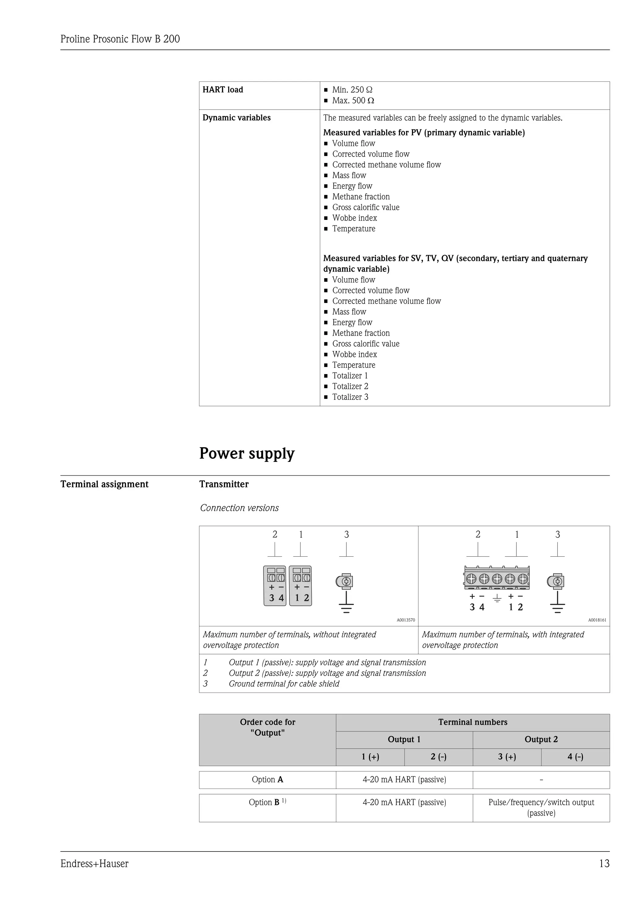
Input
Measured variable Direct measured variables
Volume flow
Calculated measured variables
• Corrected volume flow
• Mass flow
Optional measured variables (can be ordered)
Order code for "Sensor version", option 2 "Volume flow + Biogas analysis"
• Corrected methane volume flow
• Energy flow
• Methane fraction
• Gross calorific value
• Wobbe index
• Temperature
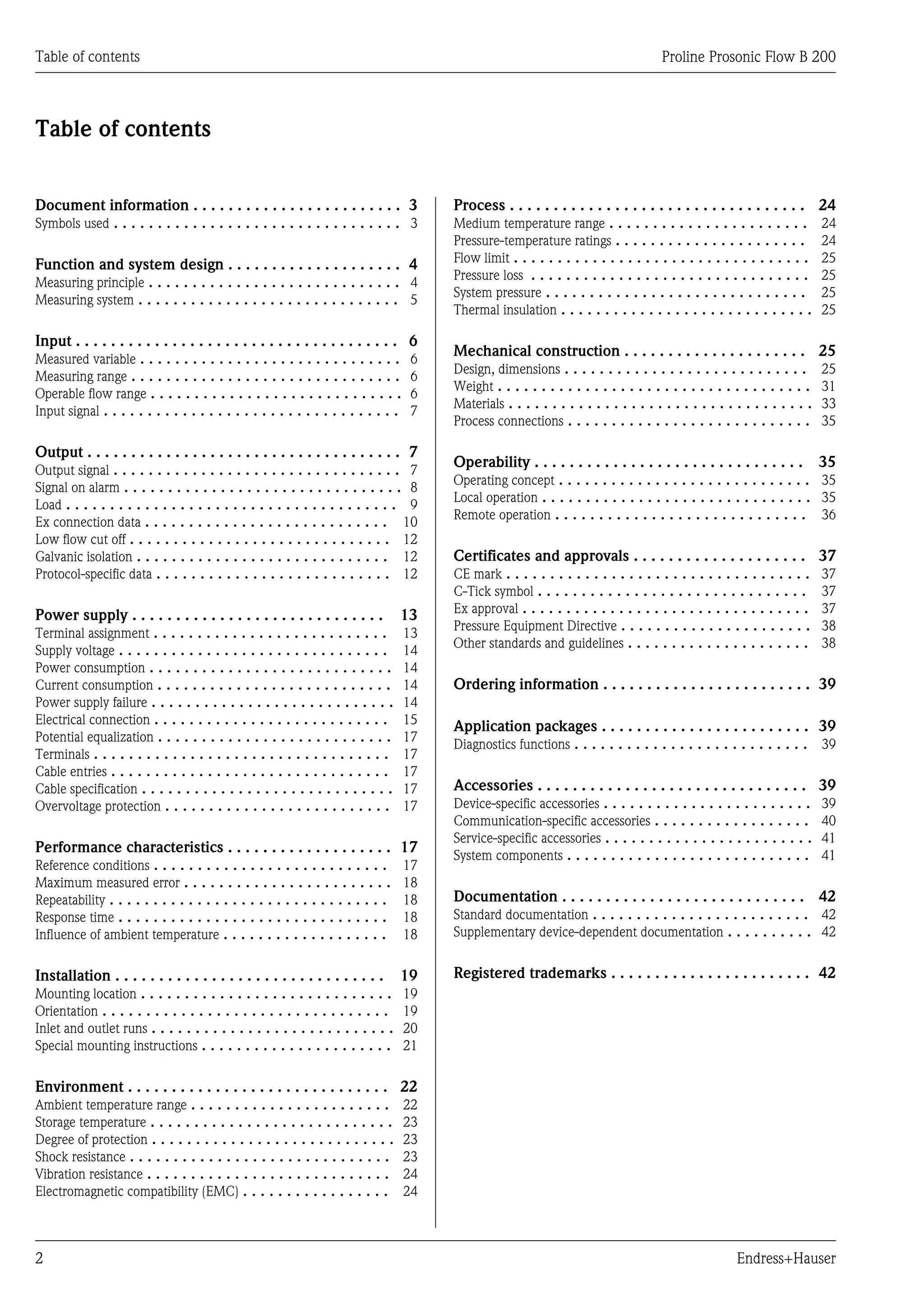
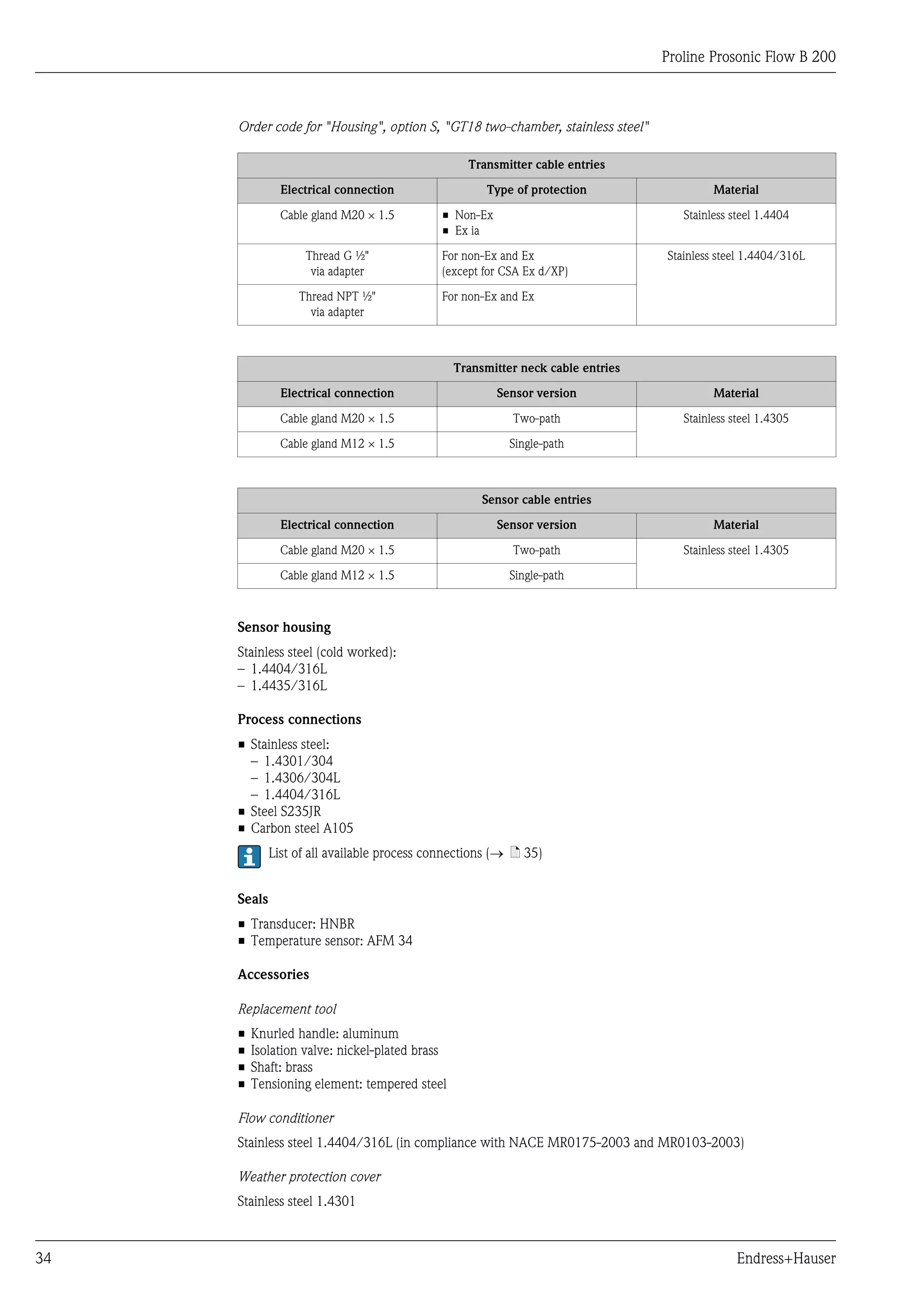
Measuring range Standard (Order code for "Calibration Flow", option 1 "Operable flow range 30 : 1")
Nominal diameter Velocity Effective volume flow
[mm] [in] [m/s] [ft/s] [m3/h] [ft3/h]
50 2 1 to 30 3.28 to 98.4 9 to 269 316 to 9 495
80 3 1 to 30 3.28 to 98.4 20 to 611 720 to 21 592
100 4 1 to 30 3.28 to 98.4 34 to 1 032 1 215 to 36 443
150 6 1 to 30 3.28 to 98.4 76 to 2 290 2 695 to 80 862
200 8 1 to 30 3.28 to 98.4 131 to 3 925 4 620 to 138 596
Optional (Order code for "Calibration Flow", option 2 "Operable flow range 100 : 1")
Nominal diameter Velocity Effective volume flow
[mm] [in] [m/s] [ft/s] [m3/h] [ft3/h]
50 2 0.3 to 30 0.98 to 98.4 3 to 269 95 to 9 495
80 3 0.3 to 30 0.98 to 98.4 6 to 611 215 to 21 592
100 4 0.3 to 30 0.98 to 98.4 11 to 1 032 363 to 36 443
150 6 0.3 to 30 0.98 to 98.4 25 to 2 290 805 to 80 862
200 8 0.3 to 30 0.98 to 98.4 43 to 3 925 1 365 to 138 596
The values in the table should only be regarded as reference values.
To calculate the measuring range, use the Applicator sizing tool (® ä 41)
Recommended measuring range
"Flow limit" section (® ä 25)
Operable flow range • 30 : 1 (standard; order code for "Calibration Flow", option 1 "Operable flow range 30 : 1")
• 100 : 1 (optional; order code for "Calibration Flow", option 2 "Operable flow range 100 : 1")
Flow rates above the preset full scale value do not overload the amplifier so the totalized values are
registered correctly.
6 Endress+Hauser](https://image.slidesharecdn.com/ti01018den0212-130313223927-phpapp02/75/Ultrasonic-flowmeter-Biogas-measurement-6-2048.jpg)
![Proline Prosonic Flow B 200
Rb [W]
1 1.1 1.2
600
500
400
300
220
200
100
0
14 16 18 20 22 24 26 28 30 32 34 36 Us [V]
16.8 23 35
A0018972
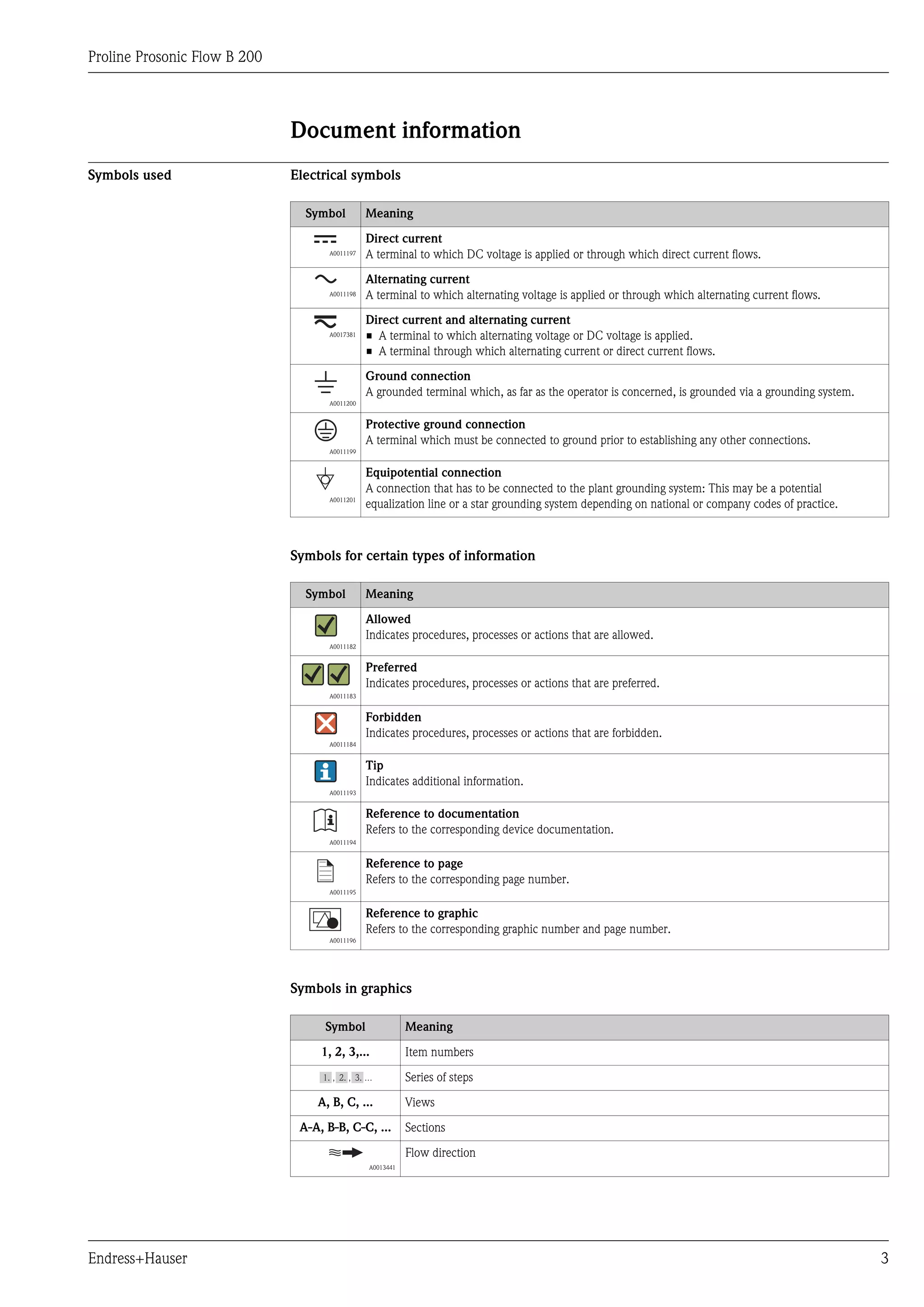
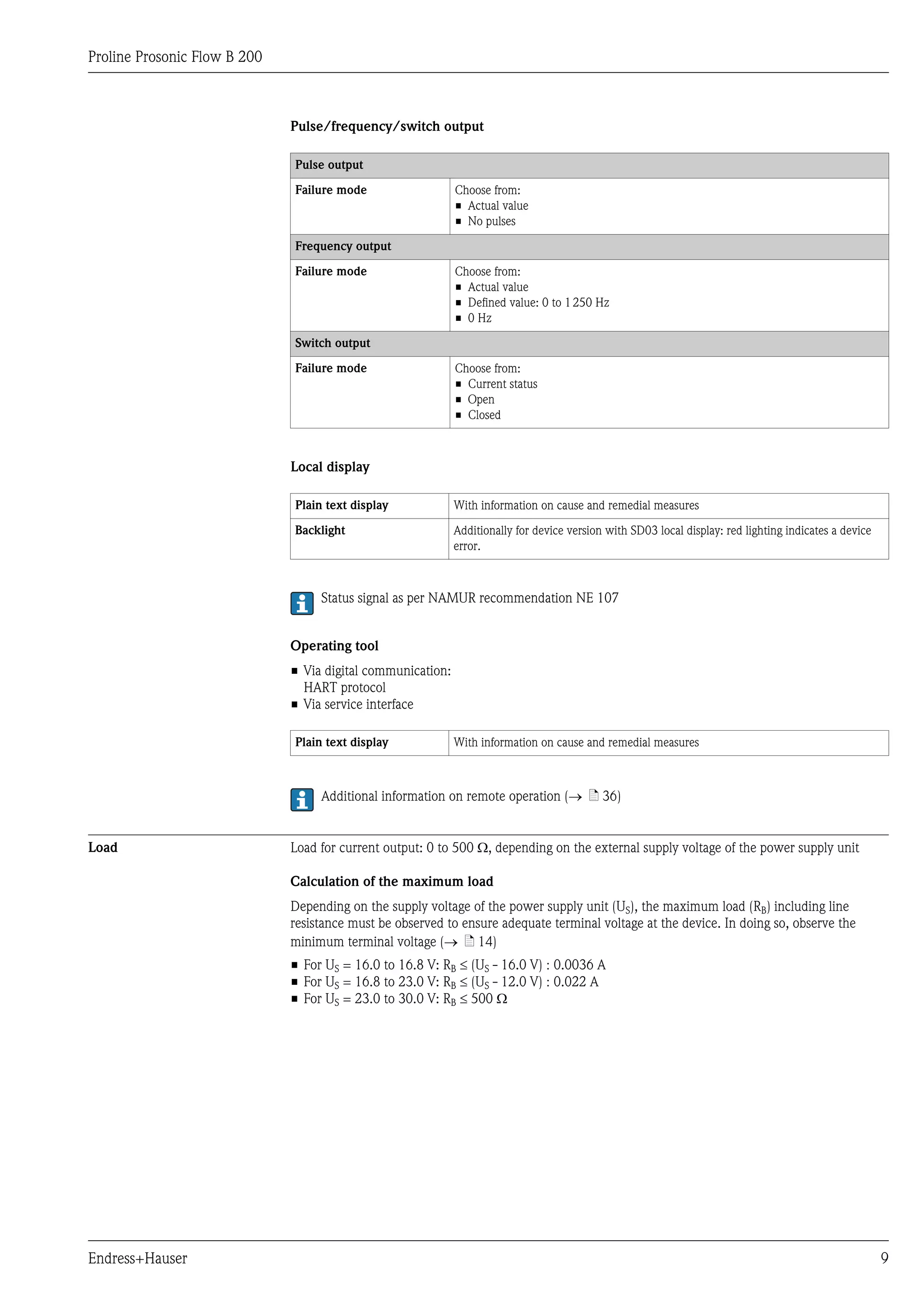
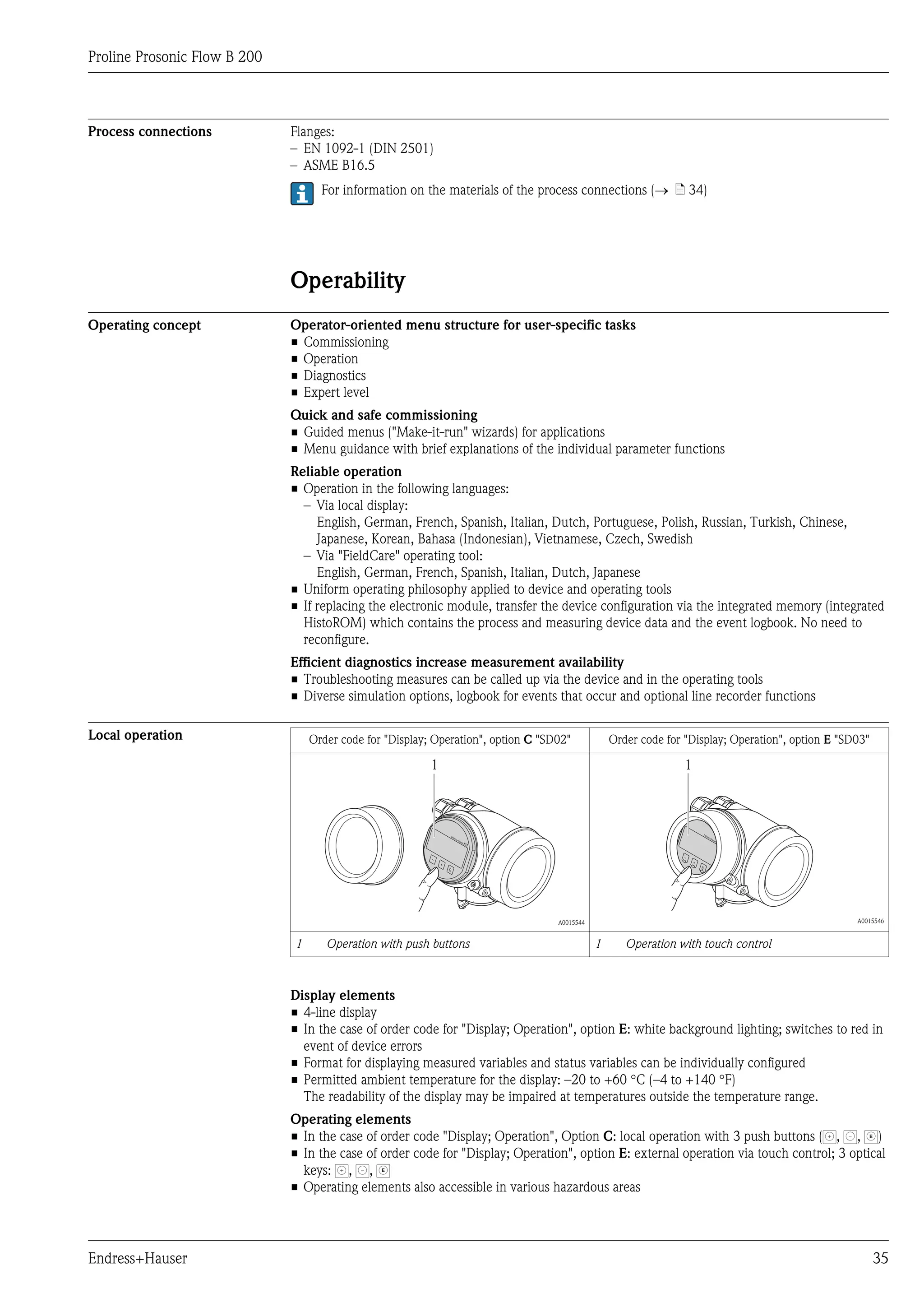
1 Operating range
1.1 For order code for "Output", option A "4-20 mA HART"/option B "4-20 mA HART, pulse/frequency/switch
output" with Ex i and option C "4-20 mA HART, 4-20 mA"
1.2 For order code for "Output", option A "4-20 mA HART"/option B "4-20 mA HART, pulse/frequency/switch
output" with non-Ex and Ex d
Sample calculation
Supply voltage of the power supply unit: US = 17.5 V
Maximum load: RB £ (17.5 V - 12.0 V) : 0.022 A = 250 W
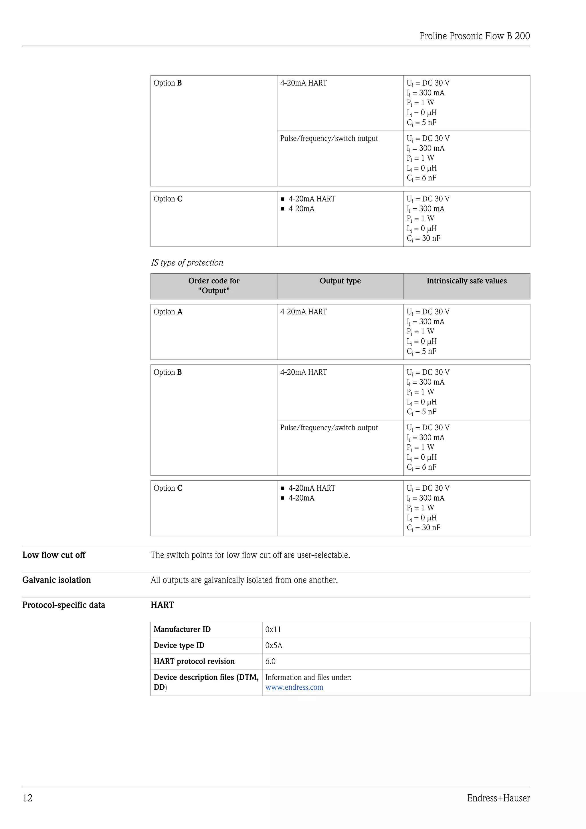
Ex connection data Safety-related values
Ex d type of protection
Order code for Output type Safety-related values
"Output"
Option A 4-20mA HART Unom = DC 35 V
Umax = 250 V
Option B 4-20mA HART Unom = DC 35 V
Umax = 250 V
Pulse/frequency/switch output Unom = DC 35 V
Umax = 250 V
Pmax = 1 W 1)
1) Internal circuit limited by Ri = 760.5 W
Option C • 4-20mA HART Unom = DC 30 V
• 4-20mA Umax = 250 V
Type of protection XP
Order code for Output type Safety-related values
"Output"
Option A 4-20mA HART Unom = DC 35 V
Umax = 250 V
Option B 4-20mA HART Unom = DC 35 V
Umax = 250 V
Pulse/frequency/switch output Unom = DC 35 V
Umax = 250 V
Pmax = 1 W 1)
1) Internal circuit limited by Ri = 760.5 W
10 Endress+Hauser](https://image.slidesharecdn.com/ti01018den0212-130313223927-phpapp02/75/Ultrasonic-flowmeter-Biogas-measurement-10-2048.jpg)
![Proline Prosonic Flow B 200
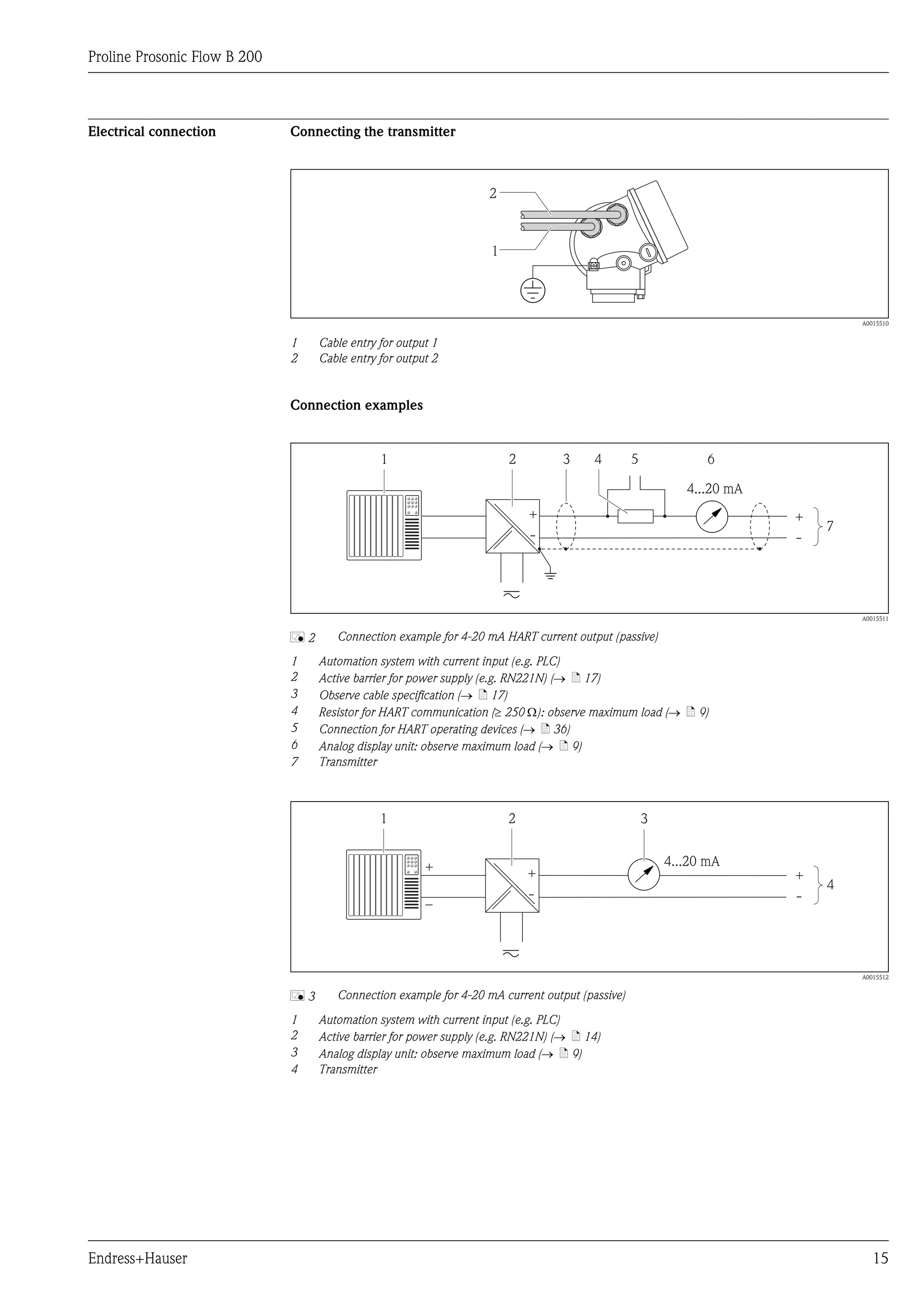
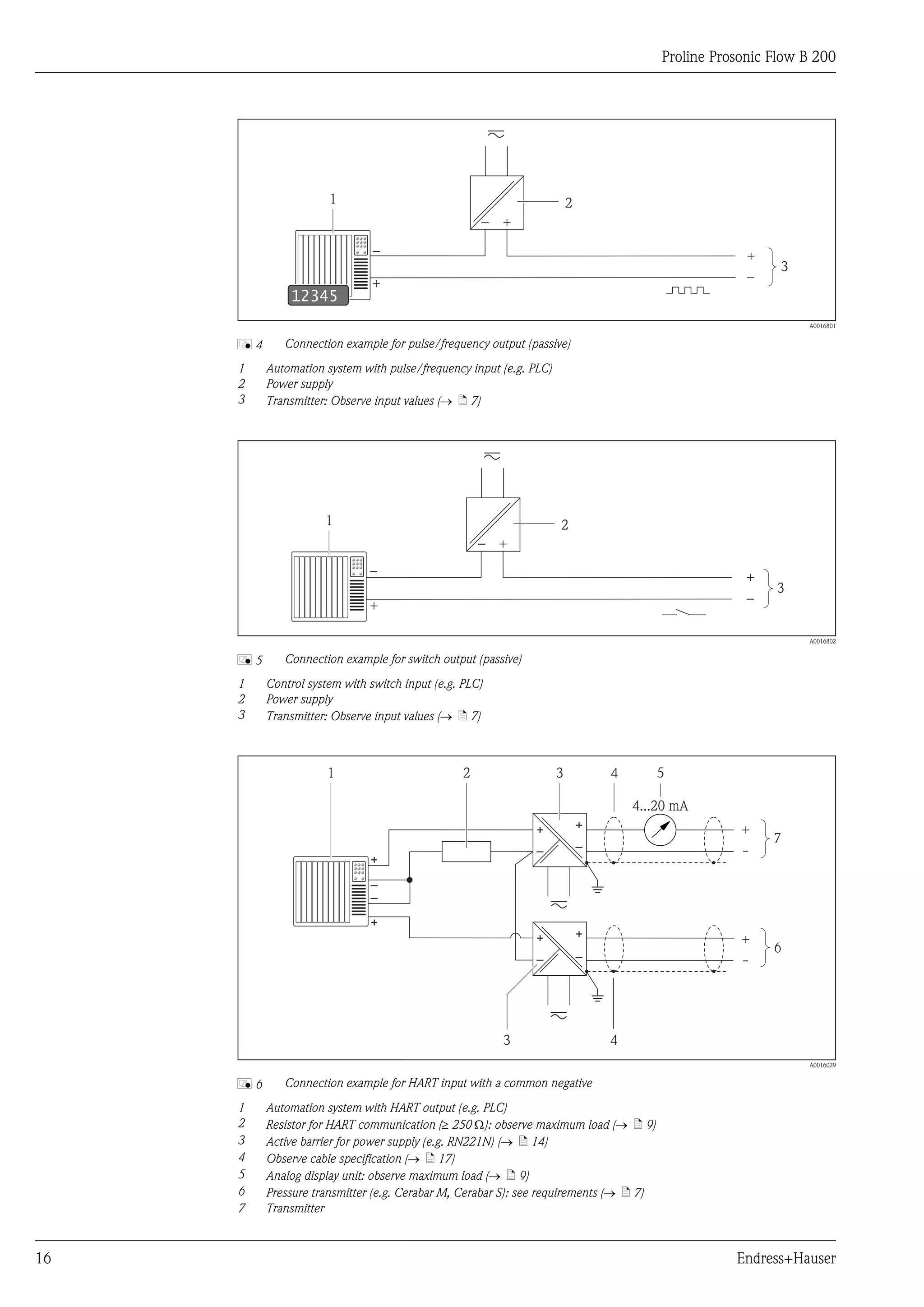
Maximum measured error In addition to the values indicated, the measured error at the current output is typically ±4 mA.
o.r. = of reading; o.f.s. = of full scale value; abs. = absolute; 1 g/cm3 = 1 kg/l; T = medium temperature
Volume flow
Standard • ±1.5 % o.r. for 3 to 30 m/s (9.84 to 98.4 ft/s)
Order code for "Calibration", option 1 • ±3 % o.r. for 1 to 3 m/s (3.28 to 9.84 ft/s)
Optional • ±0.1 % o.f.s. for 0.3 to 1 m/s (0.98 to 3.28 ft/s)
Order code for "Calibration", option 2 • ±1.5 % o.r. for 1 to 30 m/s (3.28 to 98.4 ft/s)
Methane
±2 % o.f.s. = ±2 % abs.
Temperature
±0.6 °C ± 0.005 × T °C (±0.9 °F ± 0.005 × (T – 32) °F)
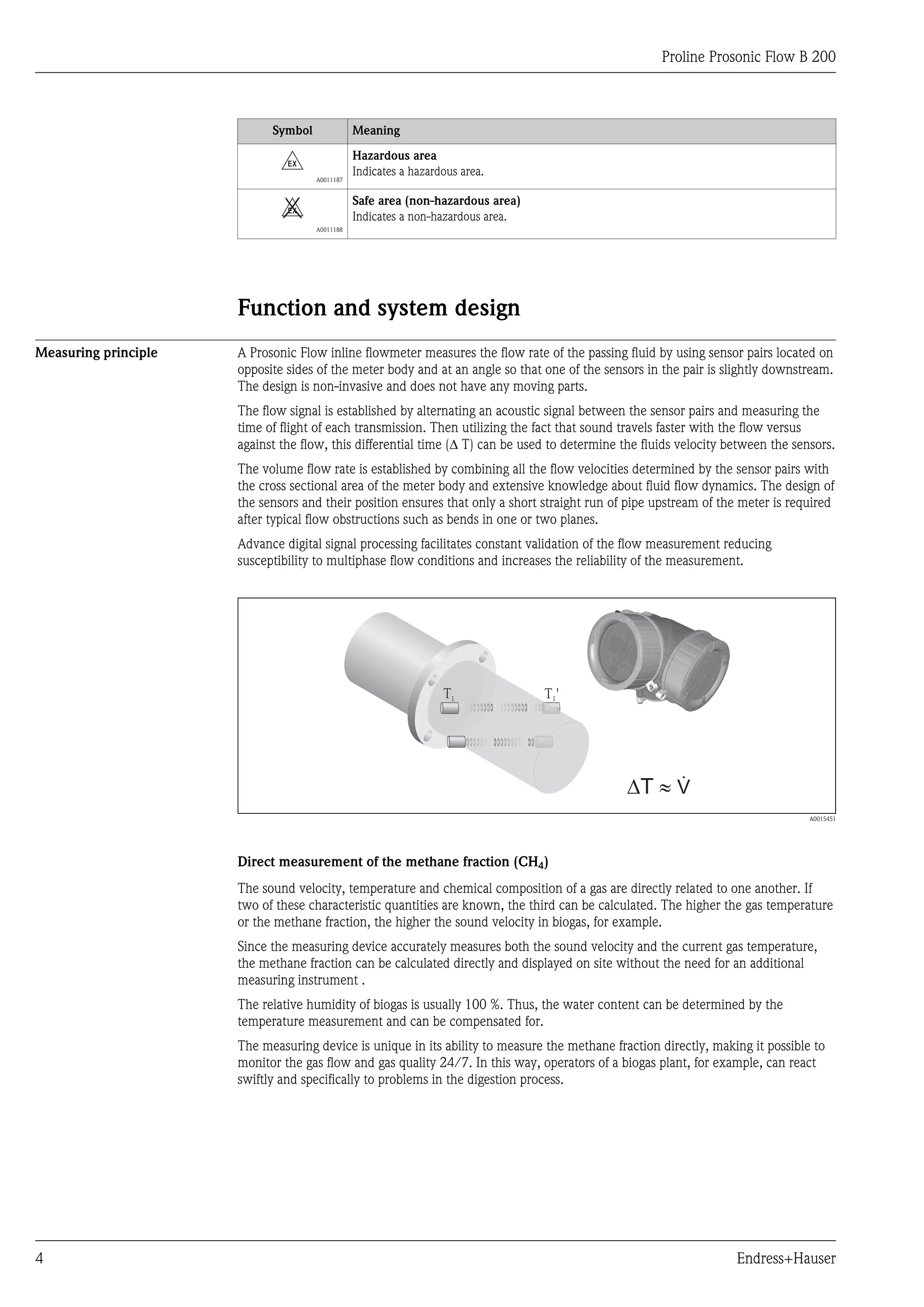
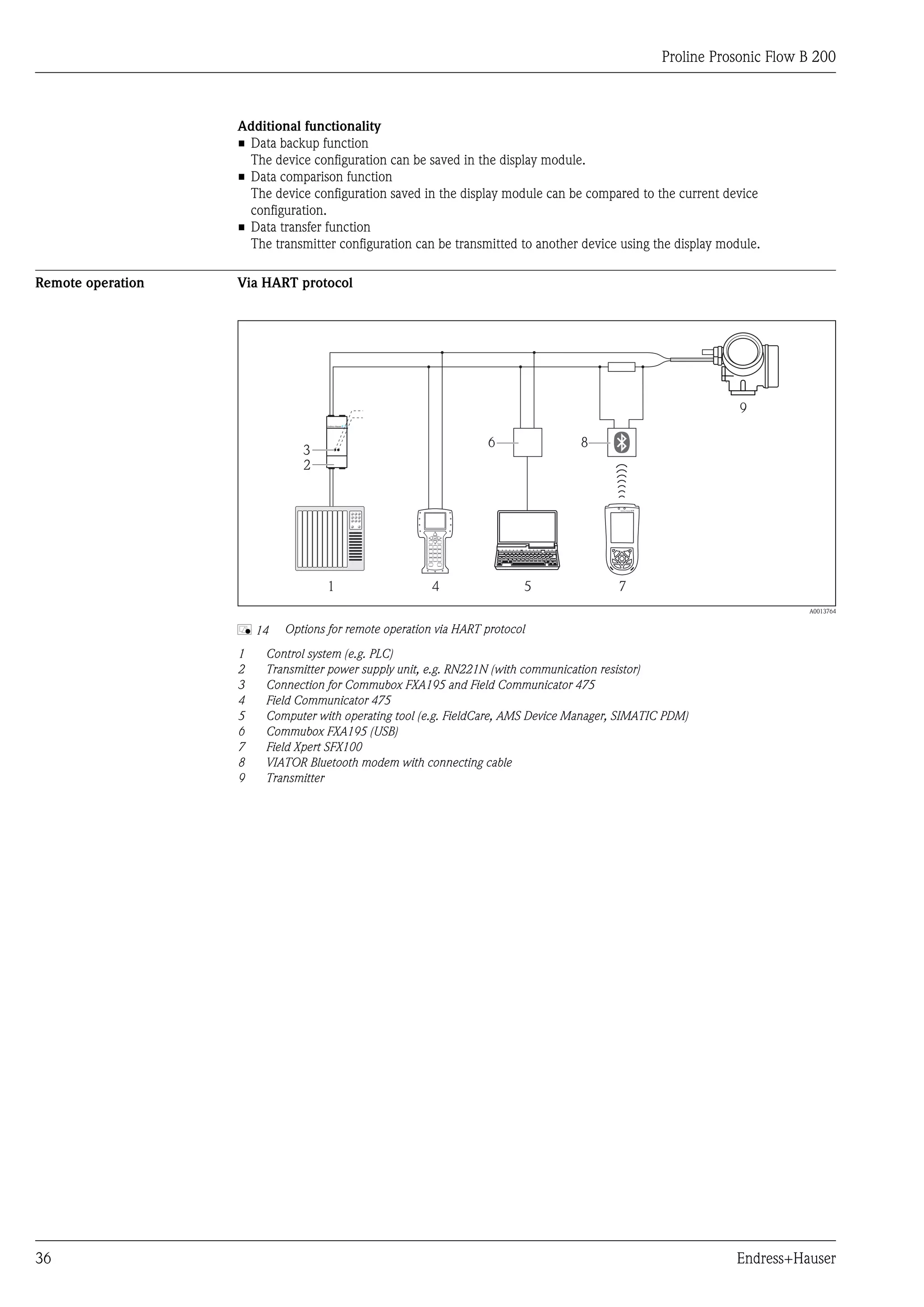
Example for max. measured error (volume flow)
[%]
10.0
9.0
8.0 2
7.0
6.0 1
5.0
4.0
3.0
2.0
1.0
0
0 1 2 3 4 5 6 7 8 30 [m/s]
v
0 5 10 15 20 25 100 [ft/s]
A0015541
å7 Example for max. measured error (volume flow) in % o.r.
1 Standard (order code for "Calibration", option 1)
2 Optional (order code for "Calibration", option 2)
Repeatability o.r. = of reading; o.f.s. = of full scale value; abs. = absolute; 1 g/cm3 = 1 kg/l; T = medium temperature
Volume flow
±0.5 % o.r.
Methane
±0.5 % o.f.s. = ±0.5 % abs.
Temperature
±0.3 °C ± 0.0025 × T °C (±0.45 °F ± 0.0025 × (T – 32) °F)
Response time • The response time depends on the configuration (damping).
• Response time in the event of erratic changes in the flow: after 1 000 ms 95 % of the full scale value.
Influence of ambient o.r. = of reading; o.f.s. = of full scale value
temperature
Current output
Additional error, in relation to the span of 16 mA:
18 Endress+Hauser](https://image.slidesharecdn.com/ti01018den0212-130313223927-phpapp02/75/Ultrasonic-flowmeter-Biogas-measurement-18-2048.jpg)
![Proline Prosonic Flow B 200
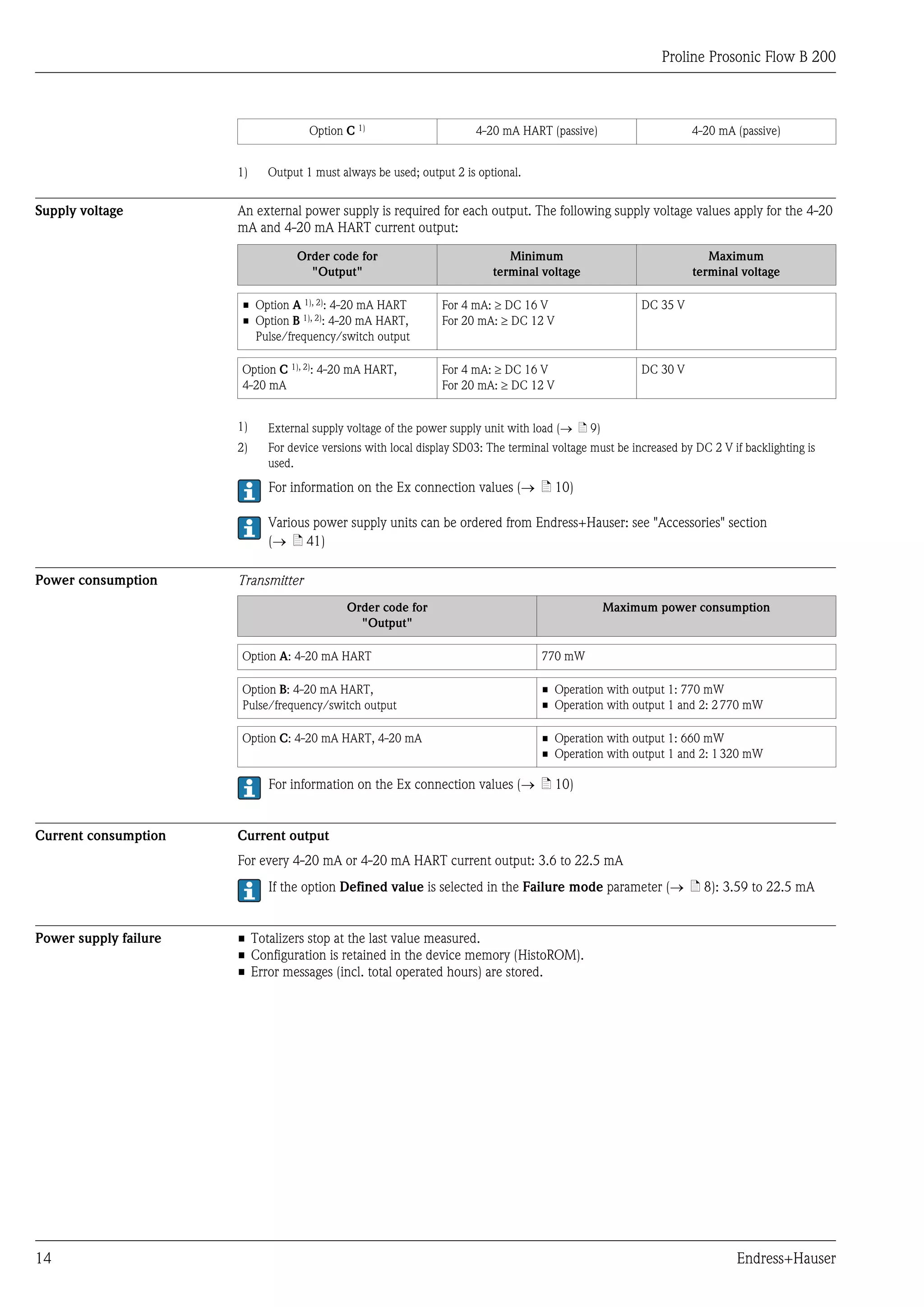
Pressure loss
The pressure loss for flow conditioners is calculated as follows:
Dp [mbar] = 0.0085 · r [kg/m3] · v2 [m/s]
Example for biogas
p = 1 040 mbar abs.
r = 1.0432 kg/m3 at t = 54 °C (129 °F)
v = 7 m/s
Dp = 0.0085 · 1.0432 kg/m3 · 49 m/s = 0.434 mbar
---
abs.: absolute
r: density of the process medium
v: average flow velocity
Environment
Ambient temperature range Transmitter –40 to +60 °C (–40 to +140 °F)
Local display –20 to +60 °C (–4 to +140 °F), the readability of the display may be impaired
at temperatures outside the temperature range.
Sensor • Flange material carbon steel: –10 to +60 °C (+14 to +140 °F)
• Flange material stainless steel: –40 to +60 °C (–40 to +140 °F)
• Version without flange: –40 to +60 °C (–40 to +140 °F)
► If operating outdoors:
Avoid direct sunlight, particularly in warm climatic regions.
Weather protection covers can be ordered from Endress+Hauser: see "Accessories" section (® ä 39)
Temperature tables
The following interdependencies between the permitted ambient and fluid temperatures apply when
operating the device in hazardous areas:
The following applies for installations with overvoltage protection in conjunction with approval code BJ or IJ:
Ta = Ta - 2 °C (Ta = Ta - 3.6 °F)
Order code for "Output", option A "4-20mA HART"
Ex ia, Ex d, CCSAUS IS, CCSAUS XP, CCSAUS NI
SI units
Nominal diameter Ta T6 T5 T4 T3 T2 T1
[mm] [°C] [85 °C] [100 °C] [135 °C] [200 °C] [300 °C] [450 °C]
50 to 200 40 60 80 80 80 80 80
50 to 200 50 – 80 80 80 80 80
50 to 200 60 – 80 80 80 80 80
US units
Nominal diameter Ta T6 T5 T4 T3 T2 T1
[in] [°F] [185 °F] [212 °F] [275 °F] [392 °F] [572 °F] [842 °F]
2 to 8 104 140 176 176 176 176 176
2 to 8 122 – 176 176 176 176 176
2 to 8 140 – 176 176 176 176 176
22 Endress+Hauser](https://image.slidesharecdn.com/ti01018den0212-130313223927-phpapp02/75/Ultrasonic-flowmeter-Biogas-measurement-22-2048.jpg)
![Proline Prosonic Flow B 200
Order code for "Output", option B "4-20mA HART, pulse/frequency/switch output"
Ex ia, Ex d, CCSAUS IS, CCSAUS XP, CCSAUS NI
SI units
Nominal diameter Ta T6 T5 T4 T3 T2 T1
[mm] [°C] [85 °C] [100 °C] [135 °C] [200 °C] [300 °C] [450 °C]
50 to 200 40 – 1) 80 80 80 80 80
2)
50 to 200 50 – 60 80 80 80 80
50 to 200 60 – – 80 80 80 80
1) Ta = 60 °C for pulse/frequency/switch output Pi £ 0.85 W
2) Ta = 80 °C for pulse/frequency/switch output Pi £ 0.85 W
US units
Nominal diameter Ta T6 T5 T4 T3 T2 T1
[in] [°F] [185 °F] [212 °F] [275 °F] [392 °F] [572 °F] [842 °F]
2 to 8 104 – 1) 176 176 176 176 176
2 to 8 122 – 140 2) 176 176 176 176
2 to 8 140 – – 176 176 176 176
1) Ta = 140 °F for pulse/frequency/switch output Pi £ 0.85 W
2) Ta = 176 °F for pulse/frequency/switch output Pi £ 0.85 W
Order code for "Output", option C "4-20mA HART, 4-20mA"
Ex ia, Ex d, CCSAUS IS, CCSAUS XP, CCSAUS NI
SI units
Nominal diameter Ta T6 T5 T4 T3 T2 T1
[mm] [°C] [85 °C] [100 °C] [135 °C] [200 °C] [300 °C] [450 °C]
50 to 200 40 60 80 80 80 80 80
50 to 200 50 – 80 80 80 80 80
50 to 200 60 – 55 80 80 80 80
US units
Nominal diameter Ta T6 T5 T4 T3 T2 T1
[in] [°F] [185 °F] [212 °F] [275 °F] [392 °F] [572 °F] [842 °F]
2 to 8 104 140 176 176 176 176 176
2 to 8 122 – 176 176 176 176 176
2 to 8 140 – 131 176 176 176 176
Storage temperature –40 to +80 °C (–40 to +176 °F), preferably at +20 °C (+68 °F)
Degree of protection Transmitter
• As standard: IP66/67, type 4X enclosure
• When housing is open: IP20, type 1 enclosure
• Display module: IP22, type 1 enclosure
Sensor
IP66/67, type 4X enclosure
Shock resistance In accordance with EN 60721-3-4
Endress+Hauser 23](https://image.slidesharecdn.com/ti01018den0212-130313223927-phpapp02/75/Ultrasonic-flowmeter-Biogas-measurement-23-2048.jpg)
![Proline Prosonic Flow B 200
Vibration resistance Class 4M4, in accordance with EN 60721-3-4
Electromagnetic compatibility • As per IEC/EN 61326 and NAMUR Recommendation 21 (NE 21)
(EMC) • Complies with emission limits for industry as per EN 55011
Details are provided in the Declaration of Conformity.
Process
Medium temperature range Sensor
0 to +80 °C (+32 to +176 °F)
Pressure-temperature ratings The following material load diagrams refer to the entire device and not just the process connection.
Flange connection according to EN 1092-1 (DIN 2501)
[psi] [bar]
300 20
200
100 10
0 0
0 20 40 60 80 100 [°C]
40 80 120 160 200 [°F]
A0015905
å 10 With lap joint flange, stamped plate PN 10, material 1.4301/304 (DN 50 to 200 / 2 to 8")
Flange connection according to EN 1092-1 (DIN 2501)
[psi] [bar]
300 20
200
100 10
0 0
0 20 40 60 80 100 [°C]
40 80 120 160 200 [°F]
A0015906
å 11 With lap joint flange PN 10, material 1.4306/304L (DN 200 / 8")
Flange connection according to EN 1092-1 (DIN 2501)
[psi] [bar]
300 20
200
100 10
0 0
0 20 40 60 80 100 [°C]
40 80 120 160 200 [°F]
A0015932
å 12 With lap joint flange PN 10/16, materials S235JR (DN 50 to 200 / 2 to 8") and 1.4306/304L (DN 50 to 150 /
2 to 6"); With lap joint flange, stamped plate PN 10, material S235JR (DN 50 to 200 / 2 to 8")
24 Endress+Hauser](https://image.slidesharecdn.com/ti01018den0212-130313223927-phpapp02/75/Ultrasonic-flowmeter-Biogas-measurement-24-2048.jpg)
![Proline Prosonic Flow B 200
Flange connection according to ASME B16.5
[psi] [bar]
300 20
200
100 10
0 0
0 20 40 60 80 100 [°C]
40 80 120 160 200 [°F]
A0015568
å 13 With lap joint flange Class 150, materials 1.4404/316L and A105 (DN 50 to 200 / 2 to 8")
Flow limit Select the nominal diameter by optimizing between the required flow range and permissible pressure loss.
For an overview of the measuring range full scale values, see the "Measuring range" section (® ä 6)
• The minimum recommended full scale value is approx. 1/20 of the maximum full scale value.
• In most applications, 10 to 50 % of the maximum full scale value can be considered ideal.
Pressure loss There is no pressure loss.
System pressure Sensor
Max. 10 bar (145 psi)
Thermal insulation For optimum temperature and methane fraction measurement (order characteristic for "Sensor version",
option 2 "Volume flow + Biogas analysis"), make sure that heat is neither lost nor applied to the sensor.
Thermal insulation can ensure that such heat transfer does not take place.
Thermal insulation is particularly recommended in situations where there is a large difference between the
process temperature and the ambient temperature. This can result in heat convection errors during
temperature measurement. A further factor which can lead to measurement errors due to heat convection is
a low flow velocity.
Mechanical construction
Design, dimensions Compact version
Order code for "Housing", options C "GT20 two-chamber, aluminum coated" , S "GT18 two-chamber,
stainless steel"
Endress+Hauser 25](https://image.slidesharecdn.com/ti01018den0212-130313223927-phpapp02/75/Ultrasonic-flowmeter-Biogas-measurement-25-2048.jpg)
![Proline Prosonic Flow B 200
Lap joint flange; lap joint flange, stamped plate
A D
B C E F
G
mm (in) H L
A0015456
Dimensions in SI units for version without overvoltage protection
DN A B 1) C D 2) E F 2) G 3) ÆH L
[mm] [mm] [mm] [mm] [mm] [mm] [mm] [mm] [mm] [mm]
50 162 102 60 165 75 90 254 56.3 250
80 162 102 60 165 75 90 268 84.9 300
100 162 102 60 165 75 90 281 110.3 300
150 162 102 60 165 75 90 308 164.3 350
200 162 102 60 165 75 90 334 213.9 400
1) for version without local display: values - 7 mm
2) For version with overvoltage protection (OVP): values + 8 mm
3) for version without local display: values - 10 mm
Dimensions in US units for version without overvoltage protection
DN A B 1) C D 2) E F 2) G 3) ÆH L
[in] [in] [in] [in] [in] [in] [in] [in] [in] [in]
2 6.38 4.02 2.36 6.50 2.95 3.54 10.0 2.22 9.84
3 6.38 4.02 2.36 6.50 2.95 3.54 10.6 3.34 11.81
4 6.38 4.02 2.36 6.50 2.95 3.54 11.1 4.34 11.81
6 6.38 4.02 2.36 6.50 2.95 3.54 12.1 6.47 13.78
8 6.38 4.02 2.36 6.50 2.95 3.54 13.2 8.42 15.75
1) for version without local display: values - 0.28 in
2) For version with overvoltage protection (OVP): values + 0.31 in
3) for version without local display: values - 0.39 in
26 Endress+Hauser](https://image.slidesharecdn.com/ti01018den0212-130313223927-phpapp02/75/Ultrasonic-flowmeter-Biogas-measurement-26-2048.jpg)
![Proline Prosonic Flow B 200
Without flange
A D
B C E F
G
mm (in) H L
A0016233
Dimensions in SI units for version without overvoltage protection
DN A B 1) C D 2) E F 2) G 3) ÆH L
[mm] [mm] [mm] [mm] [mm] [mm] [mm] [mm] [mm] [mm]
50 162 102 60 165 75 90 254 56.3 282.5
80 162 102 60 165 75 90 268 84.9 336.5
100 162 102 60 165 75 90 281 110.3 338.0
150 162 102 60 165 75 90 308 164.3 394.0
200 162 102 60 165 75 90 334 213.9 447.0
1) For version without local display: values - 7 mm
2) For version with overvoltage protection (OVP): values + 8 mm
3) Version without local display: values - 10 mm
Dimensions in US units for version without overvoltage protection
DN A B 1) C D 2) E F 2) G 3) ÆH L
[mm] [mm] [mm] [mm] [mm] [mm] [mm] [mm] [mm] [mm]
2 6.38 4.02 2.36 6.5 2.95 3.54 10.0 2.22 11.1
3 6.38 4.02 2.36 6.5 2.95 3.54 10.6 3.34 13.2
4 6.38 4.02 2.36 6.5 2.95 3.54 11.1 4.34 13.3
6 6.38 4.02 2.36 6.5 2.95 3.54 12.1 6.47 15.5
8 6.38 4.02 2.36 6.5 2.95 3.54 13.1 8.42 17.6
1) For version without local display: values - 0.28 in
2) For version with overvoltage protection (OVP): values + 0.31 in
3) Version without local display: values - 0.39 in
Endress+Hauser 27](https://image.slidesharecdn.com/ti01018den0212-130313223927-phpapp02/75/Ultrasonic-flowmeter-Biogas-measurement-27-2048.jpg)
![Proline Prosonic Flow B 200
Process connections in SI units
Flange connections EN (DIN), ASME B16.5
D
A
B
C
+0,0 (+0.00)
mm (in) L - 4,5 (-0.18)
A0015457
Flange connections EN (DIN)
Flange according to EN 1092-1 (DIN 2501); PN 10/16: 1.4306/304L, S235JR (lap joint flange)
DN A B C ÆD L
[mm] [mm] [mm] [mm] [mm] [mm]
50 165 125 22 4 ´ 18 250
80 200 160 22 8 ´ 18 300
100 220 180 24 8 ´ 18 300
150 285 240 26 8 ´ 22 350
Flange according to EN 1092-1 (DIN 2501); PN 10: 1.4306/304L, S235JR (lap joint flange)
DN A B C ÆD L
[mm] [mm] [mm] [mm] [mm] [mm]
200 340 295 27 8 ´ 22 400
Flange according to EN 1092-1 (DIN 2501); PN 10: 1.4301/304, S235JR (lap joint flange, stamped plate)
DN A B C ÆD L
[mm] [mm] [mm] [mm] [mm] [mm]
50 165 125 22 4 ´ 17.5 250
80 200 160 25 8 ´ 17.5 300
100 220 180 26 8 ´ 17.5 300
150 285 240 29 8 ´ 21.5 350
200 340 295 34 8 ´ 21.5 400
Flange connections ASME B16.5
Flange according to ASME B16.5; Class 150: 1.4404/316L, A105 (lap joint flange)
DN A B C ÆD L
[mm] [mm] [mm] [mm] [mm] [mm]
50 152.4 120.7 21.1 4 ´ 19.1 250
80 190.5 152.4 25.9 4 ´ 19.1 300
28 Endress+Hauser](https://image.slidesharecdn.com/ti01018den0212-130313223927-phpapp02/75/Ultrasonic-flowmeter-Biogas-measurement-28-2048.jpg)
![Proline Prosonic Flow B 200
Flange according to ASME B16.5; Class 150: 1.4404/316L, A105 (lap joint flange)
DN A B C ÆD L
[mm] [mm] [mm] [mm] [mm] [mm]
100 228.6 190.5 25.9 8 ´ 19.1 300
150 279.4 241.3 27.4 8 ´ 22.4 350
200 342.9 298.5 31.0 8 ´ 22.4 400
Process connections in US units
Flange connections ASME B16.5
D
A
B
C
+0,0 (+0.00)
mm (in) L - 4,5 (-0.18)
A0015457
Flange according to ASME B16.5; Class 150: 1.4404/316L, A105 (lap joint flange)
DN A B C ÆD L
[in] [in] [in] [in] [in] [in]
2 6.00 4.75 0.83 4 ´ 0.75 9.84
3 7.50 6.00 1.02 4 ´ 0.75 11.81
4 9.00 7.50 1.02 8 ´ 0.75 11.81
6 11.00 9.50 1.08 8 ´ 0.88 13.78
8 13.50 11.75 1.22 8 ´ 0.88 15.75
Endress+Hauser 29](https://image.slidesharecdn.com/ti01018den0212-130313223927-phpapp02/75/Ultrasonic-flowmeter-Biogas-measurement-29-2048.jpg)
![Proline Prosonic Flow B 200
Accessories
Replacement tool
A
C D
B E
A0016020
Dimensions in SI units
A ÆB C D E
[mm] [mm] [mm] [mm] [mm]
108 67 131 159 330 to 430
Dimensions in US units
A ÆB C D E
[in] [in] [in] [in] [in]
4.25 2.64 5.16 6.26 13 to 17
Flow conditioner
(according to EN 1092-1 (DIN 2501))
s
D2
D1
A0001941
Dimensions in SI units
DN Pressure rating Centering diameter D1 1) / D2 2) s
[mm] [mm] [mm]
50 PN 10/16 110.0 D2 6.80
80 PN 10/16 145.3 D2 10.1
100 PN 10/16 165.3 D2 13.3
30 Endress+Hauser](https://image.slidesharecdn.com/ti01018den0212-130313223927-phpapp02/75/Ultrasonic-flowmeter-Biogas-measurement-30-2048.jpg)
![Proline Prosonic Flow B 200
DN Pressure rating Centering diameter D1 1) / D2 2) s
[mm] [mm] [mm]
150 PN 10/16 221.0 D2 20.0
200 PN 10 274.0 D1 26.3
1) The flow conditioner is fitted at the outer diameter between the bolts.
2) The flow conditioner is fitted at the indentations between the bolts.
DN Pressure rating Centering diameter D1 1) / D2 2) s
[mm] [mm] [mm]
50 Class 150 104.0 D2 6.80
80 Class 150 138.4 D1 10.1
100 Class 150 176.5 D2 13.3
150 Class 150 223.5 D1 20.0
200 Class 150 274.0 D2 26.3
1) The flow conditioner is fitted at the outer diameter between the bolts.
2) The flow conditioner is fitted at the indentations between the bolts.
Dimensions in US units
DN Pressure rating Centering diameter D1 1) / D2 2) s
[in] [in] [in]
2 Class 150 4.09 D2 0.27
3 Class 150 5.45 D1 0.40
4 Class 150 6.95 D2 0.52
6 Class 150 8.81 D1 0.79
8 Class 150 10.8 D2 1.04
1) The flow conditioner is fitted at the outer diameter between the bolts.
2) The flow conditioner is fitted at the indentations between the bolts.
Weight Weight in SI units
Compact version
All values (weight) refer to devices with EN (DIN) PN 10/16 flanges. Weight information in [kg].
Order code for "Housing", option C "GT20 two-chamber, aluminum coated"
Nominal diameter Lap joint flange Lap joint flange, stamped plate
[mm]
1.4306 S235JR 1.4301 S235JR
50 9.5 5.9
80 11.8 7.5
100 14.0 9.1
150 20.9 12.3
200 27.9 19.1
Endress+Hauser 31](https://image.slidesharecdn.com/ti01018den0212-130313223927-phpapp02/75/Ultrasonic-flowmeter-Biogas-measurement-31-2048.jpg)
![Proline Prosonic Flow B 200
Order code for "Housing", option S, "GT18 two-chamber, stainless steel"
Nominal diameter Lap joint flange Lap joint flange, stamped plate
[mm]
1.4306 S235JR 1.4301 S235JR
50 12.4 8.7
80 14.7 10.3
100 16.9 12.0
150 23.7 15.2
200 30.7 22.0
Weight in US units
Compact version
All values (weight) refer to devices with ASME B16.5, Class 150 flanges. Weight information in [lbs].
Order code for "Housing", option C "GT20 two-chamber, aluminum coated"
Nominal diameter Lap joint flange
[in]
316L A105
2 18.8
3 28.6
4 38.0
6 49.8
8 77.4
Order code for "Housing", option S "GT18 two-chamber, stainless steel"
Nominal diameter Lap joint flange
[in]
316L A105
2 25.1
3 34.9
4 44.3
6 56.1
8 83.7
Accessories
Replacement tool
Weight [kg] Weight [lbs]
3.66 8.07
Flow conditioner
Weight in SI units
DN Pressure rating Weight
[mm] [kg]
PN 10/16 0.5
50
Class 150 0.5
80 PN 10/16 1.4
32 Endress+Hauser](https://image.slidesharecdn.com/ti01018den0212-130313223927-phpapp02/75/Ultrasonic-flowmeter-Biogas-measurement-32-2048.jpg)
![Proline Prosonic Flow B 200
DN Pressure rating Weight
[mm] [kg]
Class 150 1.2
100 PN 10/16 2.4
Class 150 2.7
PN 10/16 6.3
150
Class 150 6.3
PN 10 11.5
200
Class 150 12.3
Weight in US units
DN Pressure rating Weight
[in] [lbs]
2 Class 150 1.1
3 Class 150 2.6
4 Class 150 6.0
6 Class 150 14.0
8 Class 150 27.0
Materials Transmitter housing
• Order code for "Housing", option C: aluminum coating AlSi10Mg
• Order code for "Housing", option S: stainless steel 1.4404/316L
• Window material: glass
Cable entries
Order code for "Housing", option C "GT20 two-chamber, aluminum coated"
Transmitter cable entries
Electrical connection Type of protection Material
Cable gland M20 × 1.5 • Non-Ex Plastic
• Ex ia
Thread G ½" For non-Ex and Ex Nickel-plated brass
via adapter (except for CSA Ex d/XP)
Thread NPT ½" For non-Ex and Ex
via adapter
Transmitter neck cable entries
Electrical connection Measuring path Material
Cable gland M20 × 1.5 Two-path Nickel-plated brass
Cable gland M12 × 1.5 Single-path
Sensor cable entries
Electrical connection Material
Cable gland M12 × 1.5 Nickel-plated brass
Endress+Hauser 33](https://image.slidesharecdn.com/ti01018den0212-130313223927-phpapp02/75/Ultrasonic-flowmeter-Biogas-measurement-33-2048.jpg)
![Proline Prosonic Flow B 200
Via service interface (CDI)
3 –
+
E
2 1
A0014019
1 Service interface (CDI = Endress+Hauser Common Data Interface) of the measuring device
2 Commubox FXA291
3 Computer with "FieldCare" operating tool with COM DTM "CDI Communication FXA291"
Certificates and approvals
CE mark The measuring system is in conformity with the statutory requirements of the applicable EC Directives.
These are listed in the corresponding EC Declaration of Conformity along with the standards applied.
Endress+Hauser confirms successful testing of the device by affixing to it the CE mark.
C-Tick symbol The measuring system meets the EMC requirements of the "Australian Communications and Media
Authority (ACMA)".
Ex approval The measuring device is certified for use in hazardous areas and the relevant safety instructions are provided
in the separate "Safety Instructions" (XA) document. Reference is made to this document on the nameplate.
The separate Ex documentation (XA) containing all the relevant explosion protection data is available
from your Endress+Hauser sales center.
ATEX/IECEx
Currently, the following versions for use in hazardous areas are available:
Ex d
Category Type of protection
II2G / Zone 1 Ex d[ia] IIC T6-T1 Gb
Ex ia
Category Type of protection
II2G / Zone 1 Ex ia IIC T6-T1 Gb
Endress+Hauser 37](https://image.slidesharecdn.com/ti01018den0212-130313223927-phpapp02/75/Ultrasonic-flowmeter-Biogas-measurement-37-2048.jpg)
![Proline Prosonic Flow B 200
CCSAUS
Currently, the following versions for use in hazardous areas are available:
XP
Category Type of protection
Class I Division 1 Groups ABCD XP (Ex d Flameproof version)
IS
Category Type of protection
Class I Division 1 Groups ABCD IS (Ex i Intrinsically safe version), Entity-Parameter*
NI
Category Type of protection
Class I Division 2 Groups ABCD NI (Non-incendive version), NIFW-Parameter*
*= Entity and NIFW parameters according to control drawings
NEPSI
Currently, the following versions for use in hazardous areas are available:
Ex d
Category Type of protection
Zone 1 Ex d[ia] IIC T6-T1 Gb
Ex ia
Category Type of protection
Zone 1 Ex ia IIC T6-T1 Gb
Pressure Equipment Directive The devices can be ordered with or without a PED approval. If a device with a PED approval is required, this
must be explicitly stated in the order.
• With the identification PED/G1/x (x = category) on the sensor nameplate, Endress+Hauser confirms
conformity with the "Basic Safety Requirements" specified of Appendix I of the Pressure Equipment
Directive 97/23/EC.
• Devices bearing this marking (PED) are suitable for the following types of medium:
Media in Group 1 and 2 with a vapor pressure greater than, or smaller and equal to 0.5 bar (7.3 psi)
• Devices not bearing this marking (PED) are designed and manufactured according to good engineering
practice. They meet the requirements of Art.3 Section 3 of the Pressure Equipment Directive 97/23/EC.
The range of application is indicated in tables 6 to 9 in Annex II of the Pressure Equipment Directive.
Other standards and • EN 60529
guidelines Degrees of protection provided by enclosures (IP code)
• EN 61010-1
Protection Measures for Electrical Equipment for Measurement, Control, Regulation and Laboratory
Procedures
• IEC/EN 61326
Emission in accordance with Class A requirements. Electromagnetic compatibility (EMC requirements)
• NAMUR NE 21
Electromagnetic compatibility (EMC) of industrial process and laboratory control equipment
• NAMUR NE 32
Data retention in the event of a power failure in field and control instruments with microprocessors
• NAMUR NE 43
Standardization of the signal level for the breakdown information of digital transmitters with analog output
signal.
38 Endress+Hauser](https://image.slidesharecdn.com/ti01018den0212-130313223927-phpapp02/75/Ultrasonic-flowmeter-Biogas-measurement-38-2048.jpg)

The Proline Prosonic Flow B 200 is an ultrasonic flow measuring system designed for accurate biogas measurement in variable process conditions. It features reliable measurement capabilities for wet and digester gas across various applications, with minimal pressure loss and various communication options. This device employs advanced signal processing for enhanced measurement reliability and diagnostic capabilities, making it a cost-effective solution for biogas monitoring.


