Download to read offline
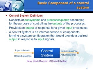

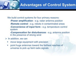
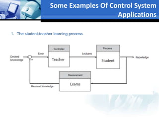
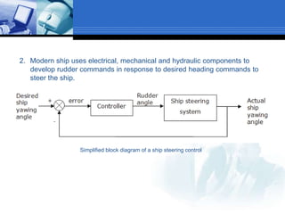
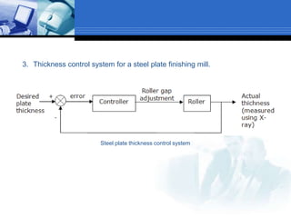
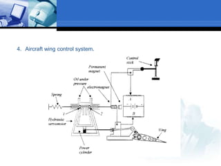
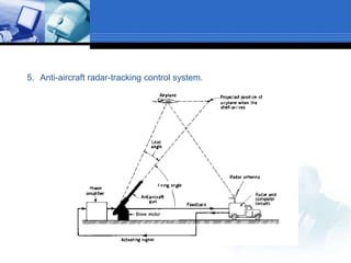
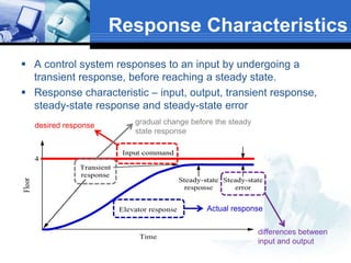

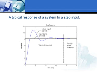
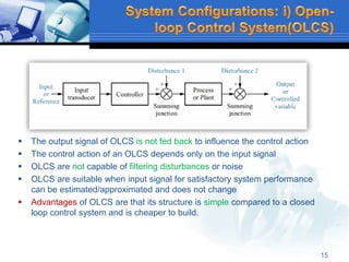
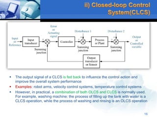
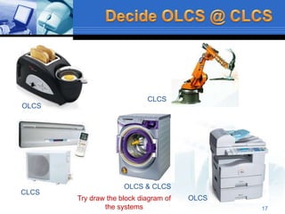
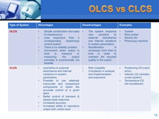
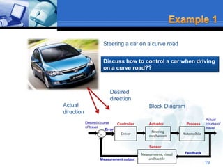
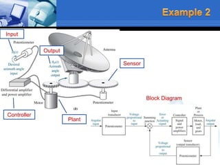

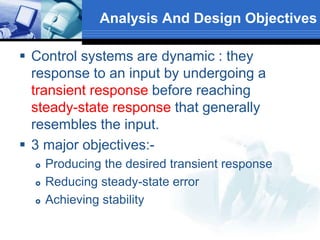
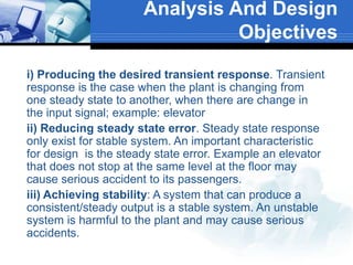


This document provides an overview of control systems. It defines a control system and its basic components. The key differences between open loop and closed loop control schemes are explained. The three main objectives of control system design and analysis are described as producing the desired transient response, reducing steady-state error, and achieving stability. Examples of control systems applications are given across various domains like ships, aircraft, manufacturing processes. The response characteristics of a control system like input, output, transient response and steady-state response are explained. The advantages and disadvantages of open loop and closed loop systems are compared. Computer aided design using simulation software is introduced as an effective way to analyze, design and test control systems.