1. TU – PE 4063/6463 – Well Completion Spring 2013
Dr. Evren M. Ozbayoglu, Tel: 918-631 5175, e-mail: evren-ozbayoglu@utulsa.edu Chapter-11, 1/45
PE 4063 / 6463 – Well Completion
CHAPTER 11 – Acidizing
It has been discussed that the many sources of formation damage which can lead to a reduction in
the permeability of the near wellbore area and creation of an extra, positive skin, as measured by
a well test. Matrix (stimulation) treatments are a common form of well intervention aimed at
removing this formation damage and restoring the well to its natural, undamaged inflow
performance. An alternative stimulation technique - propped hydraulic fracturing - will has been
covered in the previous chapter. This latter well treatment can bypass this damage and/or increase
the effective wellbore radius. Either of these stimulation treatments may be carried out
immediately after drilling the well is completed or at any time in the well’s producing lifetime
when they can be economically justified.
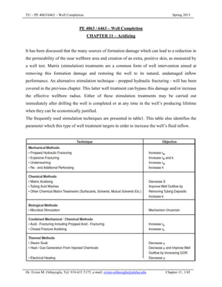
The frequently used stimulation techniques are presented in table1. This table also identifies the
parameter which this type of well treatment targets in order to increase the well’s fluid inflow.
2. TU – PE 4063/6463 – Well Completion Spring 2013
Dr. Evren M. Ozbayoglu, Tel: 918-631 5175, e-mail: evren-ozbayoglu@utulsa.edu Chapter-11, 2/45
The choice of which technique is the most appropriate for a particular well can be made with the
help of the following table.
Tubing washes are a related technique which share a similar technology, in terms of fluid and
additive selection, with matrix treatments. They are used to improve the well outflow by
removing deposits which have formed in the tubing, i.e., by increasing the (effective) tubing
radius. The treatment fluid is normally retained with in the tubing during the tubing wash
treatment and is NOT injected into the formation. This procedure avoids impairing the formation
with any undissolved particles which have become dispersed in the treatment fluid. Tubing
washes will not be discussed any further - but the requirements e.g. for corrosion inhibition if an
acid wash is selected (e.g. because the deposit in the tubing is acid soluble) is very similar to
matrix acidizing.
Matrix treatments, and acidizing in particular, aim to remove the excess flowing pressure drop
(Pd) created by the presence of a volume rock which has suffered formation damage (i.e. has a
lower than original permeability) in the near wellbore area.
3. TU – PE 4063/6463 – Well Completion Spring 2013
Dr. Evren M. Ozbayoglu, Tel: 918-631 5175, e-mail: evren-ozbayoglu@utulsa.edu Chapter-11, 3/45
The removal of this formation damage will restore the “natural” well productivity.
4. TU – PE 4063/6463 – Well Completion Spring 2013
Dr. Evren M. Ozbayoglu, Tel: 918-631 5175, e-mail: evren-ozbayoglu@utulsa.edu Chapter-11, 4/45
Matrix stimulation treatments increase well productivity by pumping a specially formulated
treatment fluid (frequently, but not always, an acid) which is designed to remove (normally
dissolve) the formation damage. However, the keys to successful treatments are:
The identification of a suitable candidate well which is capable of a greater hydrocarbon
production rate,
The selection of the optimum type of treatment fluid for the removal of the formation damage
The design of the operational aspects of the treatment such that the required economic criteria
are successfully achieved.
Well Stimulation Economics
Well stimulation is only justified when the net (discounted) monetary benefit of the resulting
extra oil or gas production is greater than the cost of the stimulation treatment. Previous field
experience from the stimulation of similar wells is often a good guide when predicting the
expected gain from the well stimulation treatment. A second simple, but approximate, method to
estimate the potential benefits from a stimulation treatment is to use the fact that the production
wells typically show a constant, long term, annual percentage decline in net hydrocarbon
production. This decline can be expressed in the form of a straight line when the logarithm of the
net hydrocarbon production is plotted against time.
5. TU – PE 4063/6463 – Well Completion Spring 2013
Dr. Evren M. Ozbayoglu, Tel: 918-631 5175, e-mail: evren-ozbayoglu@utulsa.edu Chapter-11, 5/45
Straight line with a steeper slope corresponds to a greater, annual, net hydrocarbon production
decline rate. Note the extra oil reserves created by producing the well above the economic limit
for a longer period of time.
The expected, net hydrocarbon production gain from the stimulation treatment needs to be
estimated as the first step in carrying out the economic evaluation. This can be estimated if:
The well’s skin value is known, or
By use of the Hawkins formula if the extent and depth of formation damage are known or can
be guessed with reasonable confidence.
Field experience has shown that this gain in production will normally be followed by an
increased production decline rate. In time, the well’s production rate will often revert to its
predicted, original (unstimulated) value or even drop below this extrapolated value. The latter
occurs if the well’s reserves have undergone an accelerated depletion resulting from the increased
well production following the well stimulation.
Thus an estimate of the length of time that the well stimulation treatment will increase the well
production is also required. Remember that these prognoses must not only consider:
The well inflow i.e. whether the well has sufficient inflow capacity and remaining reserves;
The well (tubing) outflow capacity and
6. TU – PE 4063/6463 – Well Completion Spring 2013
Dr. Evren M. Ozbayoglu, Tel: 918-631 5175, e-mail: evren-ozbayoglu@utulsa.edu Chapter-11, 6/45
Whether the production facilities have sufficient capacity to process the extra fluid volumes.
The above, or other techniques, allow the net hydrocarbon production gain from the stimulation
to be estimated. These volumes should be reduced by the:
Appropriate discount rate (since hydrocarbons produced today are more valuable than later
hydrocarbon production). Any reductions in facility capacity while the spent stimulation
fluids are being treated must also be included in the economic evaluation.
Hydrocarbon production lost while the well was taken off production to carry out the well
stimulation treatment,
Expected chance that the stimulation will be successful (this is often significantly lower than
100%).
The resulting increased revenue can be calculated from this discounted increase in net
hydrocarbon production multiplied by the net revenue per unit of production (sales price
minus marginal operating expenditure and taxes plus royalties). This has to be compared with
the cost of the stimulation which should include the:
Cost of mobilization and rental of equipment (pumps, tanks etc.) and personnel employed for
the well stimulation treatment. Also the cost of returning the well to production e.g. initiate
production by lifting with nitrogen gas. These costs are related to the type of stimulation
chosen and the stimulation treatment size.
Cost of consumables e.g. chemicals etc. used for the well stimulation treatment. This cost is
related to the size of the stimulation treatment, while the earlier ones are related to the type of
stimulation treatment chosen.
From the point of view of stimulation candidate well selection, the well stimulation treatment
yielding the highest prognosed (discounted) rate of return is the treatment which, in principle,
should be carried out first.
A somewhat simpler calculation method is to calculate the payback time, i.e., the production time
required for the increased, net hydrocarbon production to pay back the costs of the well
stimulation treatment. The most profitable well stimulation candidate is the stimulation treatment
yielding the most rapid pay back. Most production companies require a very high rate of return
from this type of well treatment, leading to pay back times of between 6 and 12 months from this
type of well treatment.
7. TU – PE 4063/6463 – Well Completion Spring 2013
Dr. Evren M. Ozbayoglu, Tel: 918-631 5175, e-mail: evren-ozbayoglu@utulsa.edu Chapter-11, 7/45
Candidate Selection
The selection of stimulation candidates that potentially meet the economic screening criteria
discussed in the previous section is the key to a successful stimulation campaign. This involves
two stages:
The identification and (accurate) quantification of those parameters which control the
productivity of the specific well and
An analysis to determine whether the well stimulation treatment would actually improve the
well production.
It is important here to distinguish between well (inflow) productivity and well production. This is
because an improvement in the well “inflow” performance (from the reservoir to the well) can
have only a limited effect on the daily well production if the well “outflow” is limited by tubing /
artificial lift / facilities restrictions.
8. TU – PE 4063/6463 – Well Completion Spring 2013
Dr. Evren M. Ozbayoglu, Tel: 918-631 5175, e-mail: evren-ozbayoglu@utulsa.edu Chapter-11, 8/45
Following table summarizes typical values for the minimum requirements for a successful
(matrix) stimulation treatment. The criteria in this table can be used for the preliminary screening
of well stimulation candidates. These figures are based on experience from a number of fields.
They will be modified when studying specific conditions pertaining to a given field.
The above criteria evaluate whether the well has a sufficient minimum of:
Remaining reserves to justify carrying out the remedial stimulation technique,
Well inflow productivity and
Capacity in the facilities to process the extra fluid production.
The well skin (S) is not mentioned in the table, this is because the skin cannot be considered apart
from the other parameters that control the well inflow, i.e., the reservoir permeability thickness
(k.h) and the potential well drawdown (Pe - Pwf). Thus, a small reduction in skin value from a
well with a large reservoir permeability thickness can yield a much larger production increase
than removal of a high skin value from a well with a small reservoir permeability thickness.
Alternatively, installation of an artificial lift method which allows an increased drawdown or re-
perforation of the producing interval may be the more effective methods of increasing
production. Each candidate well needs to be evaluated on its own merits.
9. TU – PE 4063/6463 – Well Completion Spring 2013
Dr. Evren M. Ozbayoglu, Tel: 918-631 5175, e-mail: evren-ozbayoglu@utulsa.edu Chapter-11, 9/45
Treatment Timing
Well stimulations may be carried out immediately after the initial drilling/completion program
has been finalized e.g. to correct formation permeability impairment caused by the drilling mud.
Alternatively, the stimulation candidate may be identified as a result of routine, field production
surveillance e.g. the well is identified as producing less than the surrounding wells with
comparable reservoir quality or reservoir permeability thickness (kh). Following figure
schematically illustrates the typical output from a modern, production surveillance, computer
package. This type of graphical display helps with the easy recognition of potential well
stimulation candidates. Once a particular well has been identified, its attributes must be checked.
Further Treatment Selection Criteria & "The Stimulation Cycle"
Further selection criteria which should be considered include:
Is Sdam > 30 % of Stotal (the total well skin) ?
10. TU – PE 4063/6463 – Well Completion Spring 2013
Dr. Evren M. Ozbayoglu, Tel: 918-631 5175, e-mail: evren-ozbayoglu@utulsa.edu Chapter-11, 10/45
i.e. could other inflow improving measures (e.g. re-perforation) be a more economical
approach to increasing well production? Following table gives examples of poor well
productivity which cannot be “stimulated away”.
Does the well show sand production?
Are sand control measures in place? (matrix stimulation treatments of gravel packed
completions have historically shown a lower success rate than when perforated completions
are treated).
Is the cause of formation damage known (or at least suspected)?
Identification of the cause of the formation damage greatly increases the chance of matrix
treatment success since a treatment fluid which efficiently removes that specific form of
formation damage can be selected.
Is the stimulation feasible?
The final stage of stimulation candidate selection is to evaluate the practical aspects of the
stimulation (e.g. what is the mechanical condition of the well? Are there any logistical,
scheduling, or other overriding considerations which prevent the well being taken out of
production?).
11. TU – PE 4063/6463 – Well Completion Spring 2013
Dr. Evren M. Ozbayoglu, Tel: 918-631 5175, e-mail: evren-ozbayoglu@utulsa.edu Chapter-11, 11/45
Once the above questions have been answered the following choices can be made:
The composition of the pre and post-flushes and any additives are determined and the volume
of all flushes chosen. Remember that the post flush has to be displaced to the perforations by
a compatible brine or hydrocarbon fluid.
The detailed treatment design (including injection rates and pressures) can now be made and
the strategy for returning the well to production chosen.
The treatment is now carried out and, eventually, evaluated.
The complete stimulation cycle described above is captured in the following figure.
Although well stimulation is often a high reward well activity, it must be reiterated here that, for
both clastic formations and many carbonate reservoirs:
Prevention of formation damage is nearly always better than the cure (a remedial well
stimulation).
12. TU – PE 4063/6463 – Well Completion Spring 2013
Dr. Evren M. Ozbayoglu, Tel: 918-631 5175, e-mail: evren-ozbayoglu@utulsa.edu Chapter-11, 12/45
Acidization and other stimulation techniques can create formation damage
Selection of Chemical Treatment Type
The chosen chemical treatment fluid should be targeted at the particular type and location of the
formation damage to be removed or treated. The formation damage/impairment may be related
to:
Drilling, completion or workover operations,
Produced or (continually) injected fluids,
Injected fluids during specific well operations e.g. well killing.
Following table can be used to select the optimum type of chemical treatment once the type and
location of the formation damage/impairment has been identified.
Potential Formation Damage Caused by Matrix Stimulation Fluids
The reaction of the formation rock / insitu (formation/injected) fluids with an incorrectly chosen
stimulation fluid may generate further formation damage/ impairment. Such sources of formation
damage include:
13. TU – PE 4063/6463 – Well Completion Spring 2013
Dr. Evren M. Ozbayoglu, Tel: 918-631 5175, e-mail: evren-ozbayoglu@utulsa.edu Chapter-11, 13/45
Deconsolidation of the rock matrix due to the acid dissolving the cementing material that
holds the sand grains together. (Temporary) sand production is often observed when a well
is returned to production after and acid stimulation.
Generation of migrating, small diameter particles (“fines”) which can block the pore
throats. These particles result from the acid only partly dissolving the formation minerals
present between the grains. This allows insoluble, small diameter, particles to be created and
injected into the formation pore throats where bridging and blockage can occur.
The reaction products created by the chemical reaction between the acid and the formation
rock can be insoluble in the spent stimulation fluid. This is called secondary precipitation.
This precipitation process leads to blockage of the pores and pore throats (impairment). This
precipitation often does not occur immediately - this implies that the options are to either:
immediately produce the (spent) acid (i.e. return the well to production)or
inject the (spent) acid deep into the formation where any precipitation will have limited
effect on the well productivity.
Fluid incompatibilities. A matrix acidizing treatment consists of sequentially injecting a
series of fluids. It must be checked that these fluids are compatible with each other and with
the formation fluids i.e. to not form a (solid) precipitate at the prevailing, downhole
temperature when mixed in any proportion. Further, for the acid fluids which react with the
formation; both the “fresh” (unreacted) and the “spent” (reacted) acids need to be tested in
this way.
Acid precipitation of an insoluble sludge when mixed with the crude oil. This is particularly
true for asphaltenic crudes and for acids containing ferric cations (rust - or ferric oxide - is a
corrosion product produced by steel surfaces e.g. the tubing internals which is dissolved in
the acid as it is injected into the well). Such sludge precipitation can be avoided by injecting a
compatible hydrocarbon based preflush to displace the crude oil away from the wellbore and
the following acid.
Surfactants. Surfactants added to the treatment fluids may create a (highly) viscous emulsion
with the crude oil leading to blockage of the pores by this low mobility fluid. Prescreening
laboratory tests in which a sample of the treatment fluid and the crude oil are shaken together
and then the mixture examined for emulsion formation. A series of such trials can be used to
select a suitable, non-emulsifying, surfactant.
14. TU – PE 4063/6463 – Well Completion Spring 2013
Dr. Evren M. Ozbayoglu, Tel: 918-631 5175, e-mail: evren-ozbayoglu@utulsa.edu Chapter-11, 14/45
Wettability changes. Surfactants can change the wettability of the pore surfaces. An oil wet
formation has a lower permeability to oil than the equivalent water wet formation. Once
again, any surfactants that are planned to be used should be tested as described above.
“Water blocks”. Significant volumes of water are injected into the formation during the
stimulation treatment. This may lead to increased water saturation (water block) in the near
wellbore area and can take a long time to disappear (months or even years) from low
permeability formations. This can be minimized by the addition of gas to the stimulation fluid
or the (partial) replacement of water by more volatile solvents.
It is clear from above that formulation of the acid and the other fluid flushes employed is the key
to ensuring that formation damage due to the stimulation treatment does not occur or, if it is
unavoidable, is at least minimized.
Matrix Stimulation Fluid Selection
The mineralogy and chemistry of the formation, together with the chemistry of the formation
fluid and that of the formation damage, combine to give the stimulation fluid selection criteria.
This can be summarized as a balance between the:
Positive effects e.g. solubility of the formation and formation damage in the selected fluid,
and the
Negative effects e.g. deconsolidation, “fines” generation, secondary precipitates etc.
The type of formation damage present in the well has a large influence on this selection. Acid is
not always the most appropriate fluid.
Another factor which needs to be taken into account when designing the stimulation treatment is
the formation and well temperatures both during and after the well treatment. The speed of
reaction of an acid with the formation rock and / or formation damage will be greater at elevated
temperatures (typically doubling for every 10°C temperature rise). Acidic fluids are highly
corrosive to the steel surfaces that make up the completion (tubing / casing / packers etc.). The
type and concentration of corrosion inhibitor required to inhibit (i.e. limit) this corrosion reaction
depends on the treatment temperature and the treatment time during which the treatment fluids
are pumped.
15. TU – PE 4063/6463 – Well Completion Spring 2013
Dr. Evren M. Ozbayoglu, Tel: 918-631 5175, e-mail: evren-ozbayoglu@utulsa.edu Chapter-11, 15/45
The types and location of typical forms of formation damage are depicted in the figure above.
This, together with knowledge of the completion (perforated) length and associated formation
inhomogeneities (variation in permeability and pressures across the complete length), will
determine if special “diversion” arrangements need to be made. “Diversion” techniques ensure
that the treatment fluids are evenly “placed” across the formation, i.e., that at least the required
minimum volume of fluid is injected into each perforation open to flow.
Typical Acid Formulations Used for Acid Matrix Stimulation
The behavior and chemistry of the three most frequently used acids for well stimulation
treatments are discussed in the following sections.
16. TU – PE 4063/6463 – Well Completion Spring 2013
Dr. Evren M. Ozbayoglu, Tel: 918-631 5175, e-mail: evren-ozbayoglu@utulsa.edu Chapter-11, 16/45
Hydrochloric Acid (HCl)
Hydrochloric acid is widely available commercially at concentrations up to 28% wt. Its main
reaction is to dissolve carbonate minerals (or scale) present in the formation and the well itself
e.g. calcite (chalk or limestone), dolomite, siderite etc. The amount of the mineral dissolved is a
function of the volume and concentration of acid used:
Hydrochloric acid is also capable of dissolving chlorite (an iron containing clay). Hydrochloric
acid only shows secondary precipitation reactions when it reacts with iron containing minerals.
Highly impairing iron hydroxide is precipitated if the acid become spent (i.e. the pH reduces
towards the neutral value of 7).
It is essential to inhibit the acid with a corrosion inhibitor since hydrochloric acid is highly
corrosive to the conventional mild steels used in many well completions. Corrosion inhibition is
even more difficult when treating wells completed with (high cost) 13 % wt chromium (stainless
steel) alloys or one of the special duplex steels. It must also be remembered that hydrochloric
acid will dissolve any rust (ferric oxide) present on the tubing wall - even in the presence of a
corrosion inhibitor.
Organic Acids
Acetic acid (CH3COOH) is sometimes employed when it is desirable to use a weaker or slower
reacting acid than hydrochloric acid e.g. the reaction with dolomite is:
Calcium acetate has only a limited solubility - this means that 15%wt acetic acid is the maximum
concentration that should be used. Acetic acid has two major advantages:
It is non-corrosive to aluminum and (chrome) steel alloys at temperatures below 90 C.
Therefore a corrosion inhibitor is not required for these lower temperature treatments.
17. TU – PE 4063/6463 – Well Completion Spring 2013
Dr. Evren M. Ozbayoglu, Tel: 918-631 5175, e-mail: evren-ozbayoglu@utulsa.edu Chapter-11, 17/45
It retains ferric iron in solution as the acid is neutralized (“spends”) by reaction with the
formation. The chemical name for this effect is sequestration – it prevents the formation of
ferric hydroxide precipitates from the depleted acid. This avoids the highly permeability
impairing form of formation damage discussed above, that can occur with hydrochloric acid
based stimulation fluids.
Formic acid (HCOOH) behaves in a similar manner to acetic acid, but is even weaker (more
slowly reacting) than acetic acid.
Organic acids are often used to replace hydrochloric acid for treatments of higher temperature
wells, e.g., for formations with a temperature greater than 120 C. Many of the available
corrosion inhibitors are less effective at this temperature. Organic acids still require a corrosion
inhibitor at this temperature, but the corrosivity is less than that of a hydrochloric acid based of
the acid at the same temperature.
Mud Acid
The majority of acid stimulations of clastic reservoirs are carried out with “Mud Acid”. This acid
is a mixture of hydrochloric (HCl) and Hydrofluoric (HF) acids. This very aggressive acid is
capable of dissolving minerals such as quartz, clays, micas etc. (hence the name “Mud Acid”).
These minerals are inert to hydrochloric acid alone. The aggressive nature of mud acid also
means that it is a major safety hazard to the well site personnel involved in the treatment.
Exposure to the acid results in almost instantaneous blistering of the skin and permanent scarring
of the cornea (leading to sight loss).
Mud Acid is made by adding the appropriate amount of solid ammonium bifluoride to the
hydrochloric acid solution. Typical formulations used in the field are “Full Strength Mud Acid”
(12%wt HCl and 3%wt HF) and “Half Strength Mud Acid” (6%wt HCl and 1.5%wt HF). Acid
formulations with lower fluoride concentrations and higher chloride: fluoride ratio (e.g. 0.5% wt
HF and 6% wt HCl) have become more popular in recent years, as discussed at the bottom of this
section in the paragraphs concerning reprecipitation reactions.
Virtually all the chloride salts formed by the reaction of the formation (damage) with
hydrochloric acid have a high solubility. In contrast, some fluoride salts (the simple fluorides (F-
)
18. TU – PE 4063/6463 – Well Completion Spring 2013
Dr. Evren M. Ozbayoglu, Tel: 918-631 5175, e-mail: evren-ozbayoglu@utulsa.edu Chapter-11, 18/45
or the fluoro silicates (SiF6
- -
) of sodium (Na), potassium (K), calcium (Ca) etc. are very insoluble
e.g.,
The insolubility of these salts implies that mud acid should:
Never be diluted with sea water (since it contains calcium and sodium ions). The
hydrochloric acid, which forms the basis of the mud acid, is normally delivered to the wellsite
in a concentrated form and diluted on site to the designated concentration.
Never be used to acidize a carbonate formation (they contain calcium),
Always be used with a preflush of hydrochloric acid. This preflush should be of sufficient
size to dissolve these cations so that they are removed before the formation is contacted by
the mud acid. Typically, the volume of the preflush is half that of the mud acid flush. For
convenience, the preflush normally uses the same hydrochloric acid concentration as the
main, mud acid flush.
Always be overflushed with a dilute (3% wt or less) solution of hydrochloric acid (HCl) or
ammonium chloride (NH4Cl) (ammonium salts have a high solubility).
The clays, micas, etc, that are dissolved by the mud acid undergo a series of reactions that result
in precipitation of silica gel (Si(OH4) - a hydrated form of silica). This reaction can be described
in simplified form as:
SiO2 represents quartz or other forms of silica; while Al and Si represent aluminum and silicon
respectively. They are the constituents of clays and micas.
19. TU – PE 4063/6463 – Well Completion Spring 2013
Dr. Evren M. Ozbayoglu, Tel: 918-631 5175, e-mail: evren-ozbayoglu@utulsa.edu Chapter-11, 19/45
These reprecipitation reactions cannot be avoided but their effect can be minimized:
For some formations, an increase in the HCl : HF ratio of the mud acid formulation will
reduce the amount of (re)precipitation.
Since the (re)precipitation reaction occurs slowly, its damaging effects can be avoided by
producing the spent acid back rapidly (returning the well to production immediately after the
treatment has been finished) or overflushing the mud acid deep into the formation where the
effects of the reprecipitation is minimized.
This latter option and the effects of treatment size are illustrated in the following figure.
Selection of Acid Composition
The chemistry of a mud acid treatment is pictured in the figure below. It illustrates how the
impairment, formation clays and inter-granular cements are removed by the mud acid and
20. TU – PE 4063/6463 – Well Completion Spring 2013
Dr. Evren M. Ozbayoglu, Tel: 918-631 5175, e-mail: evren-ozbayoglu@utulsa.edu Chapter-11, 20/45
partially replaced by secondary reaction products. However, there is an overall increase in
porosity and permeability, leading to stimulation of the well.
21. TU – PE 4063/6463 – Well Completion Spring 2013
Dr. Evren M. Ozbayoglu, Tel: 918-631 5175, e-mail: evren-ozbayoglu@utulsa.edu Chapter-11, 21/45
The ideas presented in the previous section, combined with laboratory core flooding and field
experience, have shown the need to adjust the mud acid formulation to the type of formation
mineralogy and damage that is being treated. This experience is consolidated in the table above.
Salient points of note are:
Formations with a high (>10%wt), solubility in hydrochloric acid require a larger
(hydrochloric acid) preflush. Mud acid should not be used once this solubility level increases
to 15% wt or higher.
Higher permeability formations with low clay content can be stimulated with fluids
containing a higher HF concentration. Increasing clay contents and the presence of certain
minerals require lower HF acid concentrations and higher HCl : HF ratios.
A similar approach is followed for lower permeability formations - except that lower acid
concentrations are employed even for the “cleanest” (low clay content) formations.
This approach can be made even more specific to the particular formation by using a chemical
thermodynamic simulator to calculate the amounts of rock minerals dissolved and secondary
22. TU – PE 4063/6463 – Well Completion Spring 2013
Dr. Evren M. Ozbayoglu, Tel: 918-631 5175, e-mail: evren-ozbayoglu@utulsa.edu Chapter-11, 22/45
precipitates formed when a given volume of acid is injected into a specified formation volume.
Coupling of the thermodynamic simulator to a simplified reservoir simulation of the injection
process allows the effect of the injection of further quantities of fresh acid into the partially
acidized formation to be simulated. Changes in formation porosity can then be equated with
changes in permeability using the Kozeny Carmen relationship and the increase in production due
to the acid treatment is calculated. This process can be carried out for many acid formulations –
allowing the identification of the optimum mud acid formulation of 10% wt HCL and 0.7% wt
HF for that particular formation mineralogy.
This Figure illustrates many of the key aspects of acid formulation selection:
Obtain the highest possible Production Increase (Qacid / Qoriginal) consistent with
minimization of the increase in porosity (i.e., chance of sand production by deconsolidation
of the formation).
It can be seen from the figure above that this calculation did not include any formation damage.
An alternative formulation, 9% wt HCL and 1% wt HF, also meets the above criteria. This
23. TU – PE 4063/6463 – Well Completion Spring 2013
Dr. Evren M. Ozbayoglu, Tel: 918-631 5175, e-mail: evren-ozbayoglu@utulsa.edu Chapter-11, 23/45
second formulation has a higher HF acid content, which would be capable of removing greater
amounts of, for example, clays from drilling fluids than the 0.7% wt HF formulation. Both these
formulations have a high HCl : HF ratio, which is suitable for treating formations with significant
clay content.
Selection of Treatment Volume
The next stage in treatment design is the selection of the treatment volume. This can be based on:
Field experience when treating wells in the same or similar fields. Often between 50% and
100% of the volumes suggested in Table 7 are used.
Practical considerations such as logistics e.g.
How much acid can be delivered to the wellsite? or
How large an acid the volume pumpable during daylight hours?
Economics (how much acid can we afford based on the expected gain in hydrocarbon
production ?)
Laboratory core flow testing (acid volume required to increase the permeability by a target
amount). The core may be pre-treated to include damage to the core inlet face by the
suspected form of formation damage. Laboratory testing in support of matrix stimulation
campaigns can also include:
Identification of the formation mineralogy by use of thin sections, X-ray
diffraction or Scanning Electron Microscope studies.
24. TU – PE 4063/6463 – Well Completion Spring 2013
Dr. Evren M. Ozbayoglu, Tel: 918-631 5175, e-mail: evren-ozbayoglu@utulsa.edu Chapter-11, 24/45
Petrographic analysis of formation samples yields information on the type and
location of the minerals, porosity, cementation and clays
Fluid-Fluid compatibility tests can be carried out using API RP (Recommended
Practice) 42 test methodology. Carrying out these tests will help ensure that all the
fluids used are compatible with each other and the in-situ crude oil. Typical tests
that can be carried out include checks to see if:
A sludge is formed by the crude oil on contacting with acid,
A “fines” stabilized acid/crude oil emulsion can be formed, (these two tests
require a fresh (non-aged) crude oil sample)
A viscous oil based mud / acid emulsion is formed.
Theoretical calculation based on the formation mineralogy and formation damage. This
technique has been applied to a well in which formation damage was present to a depth of 30
cm. The following figure indicates that an acid volume of 16 US gal/ft of perforations is
required to achieve the optimum Productivity Index (PI) for both unimpaired (no formation
damage) and impaired (formation damage present) wells. However, this calculation assumes
perfect placement of the acid (see section 5.8.8). In practice, a larger acid volume has to be
injected to ensure that each perforation receives the required treatment volume of 16 US gal/ft
of perforations.
25. TU – PE 4063/6463 – Well Completion Spring 2013
Dr. Evren M. Ozbayoglu, Tel: 918-631 5175, e-mail: evren-ozbayoglu@utulsa.edu Chapter-11, 25/45
Notes:
Preflush: 40% of mud acid volume rising to 100% as carbonate content increases.
Main flush: mud acid volume between 50% and 100% of the values of Table above.
Post flush: 10% of mud acid volume if production resumed immediately increasing to 100%-
200% if production cannot be resumed within 4 hours.
Selection of Injection Rate
Matrix treatment fluids have to be injected below the Fracture Propagation Pressure (FPP) to
ensure that the fluids are injected radially from the wellbore through the matrix. The maximum
allowable injection rate can be calculated from the equation:
26. TU – PE 4063/6463 – Well Completion Spring 2013
Dr. Evren M. Ozbayoglu, Tel: 918-631 5175, e-mail: evren-ozbayoglu@utulsa.edu Chapter-11, 26/45
where Qmax = maximum injection rate (bpm), h = net treated height (ft), D = well depth (ft), µ=
viscosity of injected fluid (cp), Pe = reservoir pressure (psi), rw = wellbore radius (ft), kavr =
(average) undamaged permeability (md), gf = fracture gradient (psi/ft), Ps = safety margin (500
psi, should be larger if the fracture gradient is not well known), rf = radius of injected fluid (ft),
and s = skin factor.
This version of the radial inflow equation assumes the injected and reservoir fluids do not differ
greatly in viscosity and ignores transient flow effects. This equation allows the maximum
injection rate to be calculated for a constant bottom hole pressure as a function of skin and
injection rate. The Bottom Hole Flowing Pressures can be translated to Wellhead Pressure by
estimation of the hydrostatic head due to the density of the fluid in the tubing and any frictional
pressure drop. This requires knowledge of the treatment flow rate & fluid density, depth of the
top perforation and internal diameter roughness of the tubing etc. It can be used to prepare a
graph of Wellhead Pressure against the treatment injection rate for a number of different values
of the well skin can then be prepared.
27. TU – PE 4063/6463 – Well Completion Spring 2013
Dr. Evren M. Ozbayoglu, Tel: 918-631 5175, e-mail: evren-ozbayoglu@utulsa.edu Chapter-11, 27/45
This type of plot was first suggested by Paccaloni. He advocated plotting the treatment pump rate
against wellhead pressure so that the reduction in well skin value could be monitored in real time
as the treatment proceeded. The pump rate could also be continually maximized. This figure is
used to estimate the current skin from the pump rate / wellhead pressure data over the wide range
of pump rates experienced during the acid treatment. For this particular example there is little
change in the apparent skin value for the last three measurements (points 8, 9 and 10). Paccaloni
further proposed that the treatment should be stopped once it was observed that the apparent skin
was no longer decreasing. This Paccaloni approach to injection rate control cannot be used if the
reservoir is depleted and the wellhead pressure is zero during the treatment (“the well goes on a
vacuum”); unless some other means of real-time, bottom hole pressure measurement is available.
Selection of Additives
A range of additives to the treatment formulation have been developed to combat one or more of
the forms of formation damage associated with stimulation treatments. They can be expensive,
especially those added to acid treatments (e.g., the cost of the corrosion inhibitor required when
acidizing a high temperature well can often be greater than that of the acid). Further, many of the
additives are incompatible with each other and may cause formation damage. The use of each
additive has to be justified separately - it should not be just chosen because of the claimed
advantages in the service company sales catalogue! The more important, frequently used
additives are summarized below:
Corrosion Inhibitors
This additive type is almost always required for acid treatments due to the corroding reaction of
acid on steel:
The (acid) corrosion rate increases rapidly with increase in temperature. Further, the corrosion
inhibitor loses its effectiveness as the temperature and treatment time increase (due to
degradation). A field proven “rule-of-thumb” is that a maximum weight loss of 0.05 lb/ft2
of
28. TU – PE 4063/6463 – Well Completion Spring 2013
Dr. Evren M. Ozbayoglu, Tel: 918-631 5175, e-mail: evren-ozbayoglu@utulsa.edu Chapter-11, 28/45
tubing area (equivalent to the removal of 0.001 in of the tubing wall thickness) during the
treatment duration are acceptable. This implies that the allowable corrosion rate decreases as the
acid treatment time increases. Further, the corrosion should be in the form of a general weight
loss type rather than pitting or stress corrosion. The above allows a specification to be developed
for the corrosion inhibition of the acid. The type and concentration of corrosion inhibitor chosen
will depend on the acid type, bottom hole temperature, the type of steel contacted and the
expected treatment duration.
The “spent” acid produced back after the treatment when the well is returned to production is
often highly acidic and will corrode the tubing at a similar rate to the fresh acid. This is because
the corrosion inhibitor has been depleted by reaction with the acid and absorption on the
formation. Injection of extra corrosion inhibitor may be considered during this phase if, for
example, the well is being returned to production by nitrogen lifting with a coiled tubing unit.
Sequestering Agents
Both the ferrous (Fe++
) and ferric (Fe+++
) forms of iron will precipitate as the acid “spends” (pH
increases). They both form an amorphous, high volume iron hydroxide precipitate which is
highly efficient at creating formation damage. Fe+++
is by far the most insoluble form (see the
table below). Ferric hydroxide already has a low solubility at pH values greater than 2, though
this value is increased to 6 when mud acid is being used since sequestration takes place due to the
presence of the fluoride ion (F-). By contrast, ferrous hydroxide precipitation is delayed until the
pH rises to values greater than 6.
29. TU – PE 4063/6463 – Well Completion Spring 2013
Dr. Evren M. Ozbayoglu, Tel: 918-631 5175, e-mail: evren-ozbayoglu@utulsa.edu Chapter-11, 29/45
Iron Sulphides precipitate at any pH when hydrogen sulphide is present
The main source of Fe+++ is the acid reacting with rust in the surface tanks, flowlines and
millscale on the tubing. The Fe++ is mainly (>80%) derived from the formation minerals, e.g.,
chlorite siderite, pyrite etc.
A number of “sequestering” – or solubilizing – agents are available to increase the solubility of
iron by forming soluble complexes. The concentration of “sequestrant” required to prevent iron
hydroxide precipitation depends on the expected ferric ion (Fe+++
) concentration. This is because
it is unusual for the pH of the “spent” acid to increase to a value of 6 when treating clastic
formations unless they contain a high percentage of carbonates i.e. ferrous hydroxide does not
normally precipitate under these circumstances.
The cheapest sequestering agent is citric acid. This has the disadvantage that the maximum
concentration allowable – and the maximum amount of iron cations that can be sequestered – is
limited by the solubility of calcium citrate. A more expensive alternative, which can be used at
higher concentrations, is EDTA (Ethylene Diamine Tetracetic Acid). An alternative approach to
preventing ferric hydroxide precipitation is to reduce the Fe+++
to Fe++
by Erythorbic acid or
ascorbic acid (vitamin C). Fe+++
can catalyze the formation of an asphaltenic sludge when the
acid contacts some crude oils.
Solvents / Mutual Solvents / Surfactants
Use of these materials may reduce emulsion formation but can also be the cause of very stable
emulsion formation. Further, they may render the corrosion inhibitor ineffective by preventing
the absorption of the inhibitor onto the steel surface. They can be useful in some circumstances -
but their employment needs to be properly justified and a full range of compatibility tests carried
out.
Nitrogen
Nitrogen gas may be added to the treatment fluid to assist flow back of the spent acid and hence a
rapid clean up when treating gas wells or depleted zones.
30. TU – PE 4063/6463 – Well Completion Spring 2013
Dr. Evren M. Ozbayoglu, Tel: 918-631 5175, e-mail: evren-ozbayoglu@utulsa.edu Chapter-11, 30/45
Selection of Treatment Type
The manner of execution of most matrix treatments falls into one of two classes:
“Bullheading” - this term describes a treatment which is pumped down the production tubing.
The treatment - particularly if it employs acids - can displace rust, scale, pipe dope, etc. present
on the tubing’s inner wall into the formation; leading to formation damage. Sometimes the matrix
treatment is carried out prior to running the tubing. This can be even worse since dried mud,
cement, etc. which is present on the casing wall can now also be dislodged as well as the
damaging materials referred to above.
If the formation pressure is sufficiently high, or artificial lift is installed, it is possible to clean the
tubing with a pretreatment (known as “pickling”). This involves injecting into the tubing a
volume of acid - usually equal to 20% of the tubing contents – and displacing it until the leading
front of the acid is a safe distance above the top perforation. The acid, along with the dislodged,
potentially impairing particles, is then produced back to the surface.
Bullheading of (cold) fluids from the surface also causes the tubing to contract in length. If this
contraction generates too large tensile stresses in the tubing, the tubing may part or cause
unseating of the packer.
Pumping the treatment through a coiled tubing (CT) the end of which is positioned opposite the
perforations. Prior to the treatment being carried out the inside of the CT often needs to be
cleaned e.g. by “pickling” with acid.
However, this can relatively easily be carried out at the surface, if necessary. Coiled tubing has a
smaller diameter than production tubing - so the maximum pump rate is limited (due to friction)
and the use of ball sealers for diversion is only practical if an unusually large diameter CT is
employed.
Selection of Diversion Technique
Most formations are not homogeneous - in practice the perforated interval will contain a number
of formation layers with a range of permeabilities and, most likely, differing levels of skin
damage. The treatment fluid injection rate into each layer will be governed by the radial flow
equation since the pressure in the wellbore is in all probability very similar for all the layers. This
31. TU – PE 4063/6463 – Well Completion Spring 2013
Dr. Evren M. Ozbayoglu, Tel: 918-631 5175, e-mail: evren-ozbayoglu@utulsa.edu Chapter-11, 31/45
situation is depicted in the figure below which shows that by far the highest proportion of the acid
is injected into the middle, high permeability layer (Zone B). The natural tendency for the acid to
be injected into this layer was accentuated because this layer also has the lowest skin value. This
was due to the depth of penetration of the formation damage being the least. The Figure shows
that the formation damage in zone B alone was removed by the treatment employing V1, a small
treatment volume. Even doubling the treatment volume to V2 does not allow the acid to
successfully remove the formation damage in Zone A.
The injection rate into a particular layer, relative to the other layers, increases rapidly once the
formation damage has been removed by the treatment. Obtaining an even distribution of the
(acid) treatment is further complicated if the layers have differing pore pressures.
An extra factor to be taken into account when considering acid placement is that, in a bullhead
treatment, the treatment fluid reaches the top perforation first i.e. the first opportunity for the acid
to flow into the formation and remove of formation damage will occur in this top layer. The
32. TU – PE 4063/6463 – Well Completion Spring 2013
Dr. Evren M. Ozbayoglu, Tel: 918-631 5175, e-mail: evren-ozbayoglu@utulsa.edu Chapter-11, 32/45
effect of this process is illustrated in the figure below. This illustrates a flow meter survey made
in a vertical gas well before and after a “bullhead” matrix acid treatment. The flow rates were
adjusted so that the flowing bottom hole pressure i.e. the drawdown, was the same in both cases.
The post stimulation survey shows that the acid job was successful from an economic point of
view (50% increase in production at the same drawdown); but that the acid mainly stimulated the
top perforations. The reserves from the bottom three quarters of the top perforated interval are
possibly not being produced, unless crossflow is occurring within the reservoir. This differential
pressure depletion also could lead to large pressure differences developing between the various
formation layers, causing drilling problems for future wells.
In practice, many matrix treatments are “bullheaded” into the well but employ one of the
diversion techniques which have been developed to aid the more even fluid distribution between
the various formation layers. The more frequently used diversion techniques are:
Mechanical separation using conventional techniques: These techniques include control of the
point of fluid injection by use of retrievable bridge plugs placed in packers set between
33. TU – PE 4063/6463 – Well Completion Spring 2013
Dr. Evren M. Ozbayoglu, Tel: 918-631 5175, e-mail: evren-ozbayoglu@utulsa.edu Chapter-11, 33/45
completion zones, dual packers on a work string (equivalent to the Selective Placement Tool
(SPT)), sequential perforation etc.
34. TU – PE 4063/6463 – Well Completion Spring 2013
Dr. Evren M. Ozbayoglu, Tel: 918-631 5175, e-mail: evren-ozbayoglu@utulsa.edu Chapter-11, 34/45
Coiled Tubing (CT): Conventional CT may be used with the fluid exit ports at right angles to
the tubing so that the perforations are sprayed with a high pressure jet of treating fluid.
Alternatively, the CT may be modified with a single or dual packers to form the SPT.
Ball Sealers: Ball sealers are nylon covered balls sized so that they can seal off the
perforations Different sized balls are required depending on the perforation diameter e.g.
when “big hole” or “deep penetrating” (narrow hole) perforating charges are used. The balls
are pumped whenever it is desired to change fluid injection from one zone to another.
35. TU – PE 4063/6463 – Well Completion Spring 2013
Dr. Evren M. Ozbayoglu, Tel: 918-631 5175, e-mail: evren-ozbayoglu@utulsa.edu Chapter-11, 35/45
Viscous Fluids (gels and foams): The idea behind the use of viscous fluids is that they
increase the flow resistance in the layer taking excessive amounts of treatment fluid so that
the fluid is diverted into a new layer.
Pack the perforation tunnel with a granular particulate (typically ± 200 md). Form a low
permeability film, on the wall of the perforation. (typically < 1 md).
36. TU – PE 4063/6463 – Well Completion Spring 2013
Dr. Evren M. Ozbayoglu, Tel: 918-631 5175, e-mail: evren-ozbayoglu@utulsa.edu Chapter-11, 36/45
Typical chemicals used for both particulate and film forming diversion agents, by preparing them
in the correct particle size ranges, are:
Benzoic acid (water / oil / gas),
Sodium Chloride (NaCl or rock salt) crystals (water) and
Oil soluble resin (oil) particles.
Stimulation of Carbonate Formations
Acidizing of carbonate formations is fundamentally different from the acidizing of clastic
formations. This is due to their differing physical nature and chemistry:
Carbonates consist of very fine grains exhibiting a vugular or fracture porosity rather than the
intergranular porosity shown by sandstones.
Carbonates react much more rapidly with hydrochloric acid than sandstones, for the same
formation temperature. Also, the use of mud acid is prohibited due to the limited solubility of
calcium fluoride.
Carbonates are normally found as massive deposits of chalk, limestone or dolomite. Their
constituent particles are much smaller than the typical sand grains found in clastic formations.
They will have undergone large porosity and permeability reductions during burial and
37. TU – PE 4063/6463 – Well Completion Spring 2013
Dr. Evren M. Ozbayoglu, Tel: 918-631 5175, e-mail: evren-ozbayoglu@utulsa.edu Chapter-11, 37/45
diagenesis. Although they are often pure (>95% wt carbonate), they can also include iron
minerals, clays and silicaceous materials giving them a very variable composition.
The many possible diagenetic processes can lead to formations with similar chemical
compositions having a strength that varies from very strong to behaving similar to toothpaste.
Strong and weak layers can be present a small distance apart. This complicates the planning of
well completion - and stimulation - procedures.
Acid Composition Selection
Hydrochloric acid is used to:
Bypass drilling or completion damage by dissolving the rock matrix;
Widen natural fractures or secondary porosity so as to improve fluid conductivity to the wellbore;
Increase the effective wellbore radius by wormhole formation.
Dolomite reacts much more slowly with Hydrochloric Acid than chalk or limestone – the
optimum reaction rate is achieved with a concentration of 28 % wt HCl acid for all dolomitic
reservoirs. 15% wt HCl is used with the other carbonate formation types.
The injected acid does not dissolve the rock uniformly, instead it forms “wormholes”.
“Wormholes” consist of a main channel from which many highly branched structures are formed.
The number and extent of the wormholes depend on:
The carbonate formation’s reactivity (high reaction rates promote few, long wormholes);
The acid leak-off rate into the matrix (controlled by formation permeability, acid and
formation fluid viscosities and the injection pressure overbalance);
The presence of higher permeability streaks, fractures, vugs, etc, will determine the preferred
direction of wormhole growth.
38. TU – PE 4063/6463 – Well Completion Spring 2013
Dr. Evren M. Ozbayoglu, Tel: 918-631 5175, e-mail: evren-ozbayoglu@utulsa.edu Chapter-11, 38/45
Treatment Types for Carbonate Rock Acidizing
Matrix Treatments
Wormhole formation during matrix treatments improves the well inflow performance by
providing a high conductivity channel at depth from the wellbore. They are created using either:
39. TU – PE 4063/6463 – Well Completion Spring 2013
Dr. Evren M. Ozbayoglu, Tel: 918-631 5175, e-mail: evren-ozbayoglu@utulsa.edu Chapter-11, 39/45
Low rate, low volume, low acid concentration treatment. (Typical values are 0.004
m3
/min/m, 0.3 m3
/m and 14% wt HCl for the injection rate, injection concentration and acid
concentration respectively). The low rate and long contact time encourages wormhole
formation and the bypassing of shallow formation damage. This type of treatment is most
suitable for short intervals (< 12 m).
High(er) rate, large volume, high concentration treatment. (Typical values are 0.025
m3
/min/m, 1.6 m3
/m and 14-28 % wt HCl respectively). The larger acid volume compensates
for the reduced wormhole formation caused by the use of the higher pump rate. Ball sealers
are more effective in high rate treatments - making them more suitable for treating longer
perforated zones.
Both types of treatments have been applied with success - the preferred method probably depends
on the local situation with regard to formation damage, presence of natural fractures & vugs, etc.
Acid Wash (or Soak) Type Treatments
Wormhole formation is undesirable if the treatment objective is to remove near wellbore damage
(e.g. perforations plugged with drilling mud, cement etc) present in a new completion or after a
workover. This is because forming the wormhole will consume a large part of the available acid.
Wormhole formation is avoided by keeping the injection rate very low (<0.0002m3/min/m). The
treatment is now called an acid wash or soak. Treatment guidelines are:
Use the highest possible HCl acid concentration (max 28%) permitted by corrosion
considerations for the planned treatment time (10 hours or longer);
Use a coiled tubing (CT) to place a volume of acid, equal to the casing volume of the
perforated interval. If CT is not available the tubing should be “pickled”;
The acid should contain an iron sequestrant and, if oil based mud cake is to be removed, a
mutual solvent or dispersing surfactant.
40. TU – PE 4063/6463 – Well Completion Spring 2013
Dr. Evren M. Ozbayoglu, Tel: 918-631 5175, e-mail: evren-ozbayoglu@utulsa.edu Chapter-11, 40/45
Acidizing of Special Well Types
Gravel Packed Wells
This well type poses a number of areas where fluid inflow can be impeded due to the screen,
perforations, gravel, grave/sand interface and the near wellbore formation. Dedicated treatments
require identification of the type and location of the formation damage, e.g.:
The screen: removal of material plugging the screen requires placing (or “spotting”) the acid
across the entire screen length while minimizing inflow into the gravel pack. This is best done
by use of a CT which is moved across the completion while pumping acid. A small acid
volume is used e.g. 120% of the wellbore completion volume.
The gravel: removal of residue left from the viscosifier. Viscosifier residues are normally
best removed with solutions of enzymes (for formation temperature <65°C), hypochlorite (a
bleach) or 2% wt hydrochloric acid (at higher temperatures). A treatment volume equal to
120% of the gravel pack volume should be used together with a diverting agent which passes
through the gravel pack sand and filters out on the formation.
Near wellbore formation damage: this should be treated in a similar manner to perforated
completions, except that the available diversion techniques are much more limited due to the
presence of the gravel pack.
Horizontal Wells
Treatment of horizontal wells is no different from conventional wells with respect to the
candidate and fluid selection criteria concerned. The most common, horizontal well completion
techniques use a slotted or perforated liner or a wire wrapped screen. Cased, cemented and
perforated completions are less frequent because of the greater costs. Many of the conventional
diversion treatments (ball sealers / chemical diverters) would not be successful in the horizontal
orientation since the treatment fluid / diverter density differences will result in shutting off either
the top or bottom of the completion section. The SPT is not effective in the uncemented liner or
screen completions because of the presence of the open annulus. Diversion with a viscous fluid
(foams or gels) is a possibility, but the very large volumes required may make them operationally
impractical.
41. TU – PE 4063/6463 – Well Completion Spring 2013
Dr. Evren M. Ozbayoglu, Tel: 918-631 5175, e-mail: evren-ozbayoglu@utulsa.edu Chapter-11, 41/45
The horizontal well has been divided into a number of sections using external casing packers.
Rubber sealing elements installed on the outside of the CT seal against a polished bore installed
at regular intervals inside the liner or screen. This arrangement allows for the completion zone
between the external casing packers (ECP) to be selectively treated in two manners:
Circulation of the treatment fluid passed the mud cake, when the flow returns to the surface
via the CT / tubing annulus. This will aid removal of the mud cake;
Injection of the treatment fluid into the formation by closing the wellhead valve which
allowed this annular flow.
The regular arrangement of ECPs and polished bores allow the treatment to be repeated along the
length of the completion interval.
This method requires the installation of a large number of ECPs and polished bores during the
initial completion of the well. This is expensive (increasing the well cost) and also presents an
increased risk of failure during the initial completion. It is also often not known in advance
whether - and at which point in the horizontal wellbore - such treatments will be required.
42. TU – PE 4063/6463 – Well Completion Spring 2013
Dr. Evren M. Ozbayoglu, Tel: 918-631 5175, e-mail: evren-ozbayoglu@utulsa.edu Chapter-11, 42/45
Naturally Fractured Formations
(Natural) fractures often have conductivity many times that of the formation. In fact, in many
carbonate formations the matrix has a very low permeability and all the production comes from
the fracture. Stimulation may have two possible objectives:
Removal of damage to the fracture conductivity by drilling mud or cement;
Enhancing the (natural) fracture conductivity by dissolving the cementing materials deposited
in the fracture.
As usual, fluid acid selection depends on the treatment objectives. A key point in the fluid
selection procedure is whether the fracture contains materials insoluble in hydrochloric acid - if
so these insoluble materials will remain in the fracture and block the created permeability.
The top picture shows a clean open channel created by acidizing a pure, fractured limestone. It
appeance is contrasted with that of a similar experiment carried out on an impure, silty limestone
(lower picture). In the latter case the channel has been blocked by insoluble particles remaining
43. TU – PE 4063/6463 – Well Completion Spring 2013
Dr. Evren M. Ozbayoglu, Tel: 918-631 5175, e-mail: evren-ozbayoglu@utulsa.edu Chapter-11, 43/45
after the acidization is completed. These particles can be mobilized by the use of a silt suspending
agent (a surfactant) so that they are flushed out of the fracture when the well is returned to
production.
Similar effects are observed when creating wormholes during matrix acidizing treatments of
impure carbonate formations. If more than one fracture is connected to the wellbore, then ball
sealers can be used to divert the acid treatment from one fracture to another. In addition, the
pump rate can also be used to aid acid placement within the fracture.
Low pump rates (and hence long contact times) enhance removal of mud cake / cement etc. in
the near wellbore region;
High pump rates - even exceeding the FPP - encourage removal of fracture filling materials
from at depth from the wellbore.
44. TU – PE 4063/6463 – Well Completion Spring 2013
Dr. Evren M. Ozbayoglu, Tel: 918-631 5175, e-mail: evren-ozbayoglu@utulsa.edu Chapter-11, 44/45
Matrix Fluid Selection
45. TU – PE 4063/6463 – Well Completion Spring 2013
Dr. Evren M. Ozbayoglu, Tel: 918-631 5175, e-mail: evren-ozbayoglu@utulsa.edu Chapter-11, 45/45