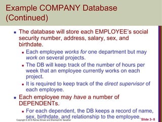
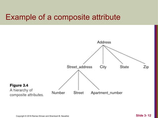
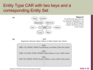
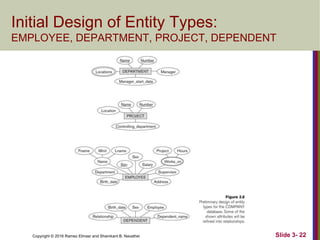
SlideShare a Scribd company logo
1 of 62
Copyright © 2016 Ramez Elmasr and Shamkant B. Navathei
CHAPTER 3
Data Modeling Using the
Entity-Relationship (ER) Model
Slide 1- 2
Copyright © 2016 Ramez Elmasr and Shamkant B. Navathei Slide 3- 3
Chapter Outline
 Overview of Database Design Process
 Example Database Application (COMPANY)
 ER Model Concepts
 Entities and Attributes
 Entity Types, Value Sets, and Key Attributes
 Relationships and Relationship Types
 Weak Entity Types
 Roles and Attributes in Relationship Types
 ER Diagrams - Notation
 ER Diagram for COMPANY Schema
 Alternative Notations – UML class diagrams, others
 Relationships of Higher Degree
Copyright © 2016 Ramez Elmasr and Shamkant B. Navathei Slide 3- 4
Overview of Database Design Process
 Two main activities:
 Database design
 Applications design
 Focus in this chapter on conceptual database
design
 To design the conceptual schema for a database
application
 Applications design focuses on the programs and
interfaces that access the database
 Generally considered part of software engineering
Copyright © 2016 Ramez Elmasr and Shamkant B. Navathei Slide 3- 5
Overview of Database Design Process
Copyright © 2016 Ramez Elmasr and Shamkant B. Navathei
Methodologies for Conceptual
Design
 Entity Relationship (ER) Diagrams (This Chapter)
 Enhanced Entity Relationship (EER) Diagrams
(Chapter 4)
 Use of Design Tools in industry for designing and
documenting large scale designs
 The UML (Unified Modeling Language) Class
Diagrams are popular in industry to document
conceptual database designs
Slide 3- 6
Copyright © 2016 Ramez Elmasr and Shamkant B. Navathei Slide 3- 7
Example COMPANY Database
 We need to create a database schema design
based on the following (simplified) requirements
of the COMPANY Database:
 The company is organized into DEPARTMENTs.
Each department has a name, number and an
employee who manages the department. We keep
track of the start date of the department manager.
A department may have several locations.
 Each department controls a number of
PROJECTs. Each project has a unique name,
unique number and is located at a single location.
Copyright © 2016 Ramez Elmasr and Shamkant B. Navathei Slide 3- 8
Example COMPANY Database
(Continued)
 The database will store each EMPLOYEE’s social
security number, address, salary, sex, and
birthdate.
 Each employee works for one department but may
work on several projects.
 The DB will keep track of the number of hours per
week that an employee currently works on each
project.
 It is required to keep track of the direct supervisor of
each employee.
 Each employee may have a number of
DEPENDENTs.
 For each dependent, the DB keeps a record of name,
sex, birthdate, and relationship to the employee.
Copyright © 2016 Ramez Elmasr and Shamkant B. Navathei Slide 3- 9
ER Model Concepts
 Entities and Attributes
 Entity is a basic concept for the ER model. Entities are
specific things or objects in the mini-world that are
represented in the database.
 For example the EMPLOYEE John Smith, the Research
DEPARTMENT, the ProductX PROJECT
 Attributes are properties used to describe an entity.
 For example an EMPLOYEE entity may have the attributes
Name, SSN, Address, Sex, BirthDate
 A specific entity will have a value for each of its attributes.
 For example a specific employee entity may have Name='John
Smith', SSN='123456789', Address ='731, Fondren, Houston,
TX', Sex='M', BirthDate='09-JAN-55‘
 Each attribute has a value set (or data type) associated with
it – e.g. integer, string, date, enumerated type, …
Copyright © 2016 Ramez Elmasr and Shamkant B. Navathei Slide 3- 10
Types of Attributes (1)
 Simple
 Each entity has a single atomic value for the attribute. For
example, SSN or Sex.
 Composite
 The attribute may be composed of several components. For
example:
 Address(Apt#, House#, Street, City, State, ZipCode, Country), or
 Name(FirstName, MiddleName, LastName).
 Composition may form a hierarchy where some components
are themselves composite.
 Multi-valued
 An entity may have multiple values for that attribute. For
example, Color of a CAR or PreviousDegrees of a STUDENT.
 Denoted as {Color} or {PreviousDegrees}.
Copyright © 2016 Ramez Elmasr and Shamkant B. Navathei Slide 3- 11
Types of Attributes (2)
 In general, composite and multi-valued attributes
may be nested arbitrarily to any number of levels,
although this is rare.
 For example, PreviousDegrees of a STUDENT is a
composite multi-valued attribute denoted by
{PreviousDegrees (College, Year, Degree, Field)}
 Multiple PreviousDegrees values can exist
 Each has four subcomponent attributes:
 College, Year, Degree, Field
Copyright © 2016 Ramez Elmasr and Shamkant B. Navathei Slide 3- 12
Example of a composite attribute
Copyright © 2016 Ramez Elmasr and Shamkant B. Navathei Slide 3- 13
Entity Types and Key Attributes (1)
 Entities with the same basic attributes are
grouped or typed into an entity type.
 For example, the entity type EMPLOYEE
and PROJECT.
 An attribute of an entity type for which each
entity must have a unique value is called a
key attribute of the entity type.
 For example, SSN of EMPLOYEE.
Copyright © 2016 Ramez Elmasr and Shamkant B. Navathei Slide 3- 14
Entity Types and Key Attributes (2)
 A key attribute may be composite.
 VehicleTagNumber is a key of the CAR entity
type with components (Number, State).
 An entity type may have more than one key.
 The CAR entity type may have two keys:
 VehicleIdentificationNumber (popularly called VIN)
 VehicleTagNumber (Number, State), aka license
plate number.
 Each key is underlined (Note: this is different from
the relational schema where only one “primary
key is underlined).
Copyright © 2016 Ramez Elmasr and Shamkant B. Navathei Slide 3- 15
Entity Set
 Each entity type will have a collection of entities
stored in the database
 Called the entity set or sometimes entity collection
 Previous slide shows three CAR entity instances in
the entity set for CAR
 Same name (CAR) used to refer to both the entity
type and the entity set
 However, entity type and entity set may be given
different names
 Entity set is the current state of the entities of that
type that are stored in the database
Copyright © 2016 Ramez Elmasr and Shamkant B. Navathei
Value Sets (Domains) of Attributes
 Each simple attribute is associated with a value
set
 E.g., Lastname has a value which is a character
string of upto 15 characters, say
 Date has a value consisting of MM-DD-YYYY
where each letter is an integer
 A value set specifies the set of values associated
with an attribute
Slide 3- 16
Copyright © 2016 Ramez Elmasr and Shamkant B. Navathei
Attributes and Value Sets
 Value sets are similar to data types in most
programming languages – e.g., integer, character
(n), real, bit
 Mathematically, an attribute A for an entity type E
whose value set is V is defined as a function
A : E -> P(V)
Where P(V) indicates a power set (which means all
possible subsets) of V. The above definition
covers simple and multivalued attributes.
 We refer to the value of attribute A for entity e as
A(e). Slide 3- 17
Copyright © 2016 Ramez Elmasr and Shamkant B. Navathei Slide 3- 18
Displaying an Entity type
 In ER diagrams, an entity type is displayed in a
rectangular box
 Attributes are displayed in ovals
 Each attribute is connected to its entity type
 Components of a composite attribute are
connected to the oval representing the composite
attribute
 Each key attribute is underlined
 Multivalued attributes displayed in double ovals
 See the full ER notation in advance on the next
slide
Copyright © 2016 Ramez Elmasr and Shamkant B. Navathei Slide 3- 19
NOTATION for ER diagrams
Copyright © 2016 Ramez Elmasr and Shamkant B. Navathei Slide 3- 20
Entity Type CAR with two keys and a
corresponding Entity Set
Copyright © 2016 Ramez Elmasr and Shamkant B. Navathei Slide 3- 21
Initial Conceptual Design of Entity Types
for the COMPANY Database Schema
 Based on the requirements, we can identify four
initial entity types in the COMPANY database:
 DEPARTMENT
 PROJECT
 EMPLOYEE
 DEPENDENT
 Their initial conceptual design is shown on the
following slide
 The initial attributes shown are derived from the
requirements description
Copyright © 2016 Ramez Elmasr and Shamkant B. Navathei Slide 3- 22
Initial Design of Entity Types:
EMPLOYEE, DEPARTMENT, PROJECT, DEPENDENT
Copyright © 2016 Ramez Elmasr and Shamkant B. Navathei Slide 3- 23
Refining the initial design by introducing
relationships
 The initial design is typically not complete
 Some aspects in the requirements will be
represented as relationships
 ER model has three main concepts:
 Entities (and their entity types and entity sets)
 Attributes (simple, composite, multivalued)
 Relationships (and their relationship types and
relationship sets)
 We introduce relationship concepts next
Copyright © 2016 Ramez Elmasr and Shamkant B. Navathei Slide 3- 24
Relationships and Relationship Types (1)
 A relationship relates two or more distinct entities with a
specific meaning.
 For example, EMPLOYEE John Smith works on the ProductX
PROJECT, or EMPLOYEE Franklin Wong manages the
Research DEPARTMENT.
 Relationships of the same type are grouped or typed into
a relationship type.
 For example, the WORKS_ON relationship type in which
EMPLOYEEs and PROJECTs participate, or the MANAGES
relationship type in which EMPLOYEEs and DEPARTMENTs
participate.
 The degree of a relationship type is the number of
participating entity types.
 Both MANAGES and WORKS_ON are binary relationships.
Copyright © 2016 Ramez Elmasr and Shamkant B. Navathei Slide 3- 25
Relationship instances of the WORKS_FOR N:1
relationship between EMPLOYEE and DEPARTMENT
Copyright © 2016 Ramez Elmasr and Shamkant B. Navathei Slide 3- 26
Relationship instances of the M:N WORKS_ON
relationship between EMPLOYEE and PROJECT
Copyright © 2016 Ramez Elmasr and Shamkant B. Navathei Slide 3- 27
Relationship type vs. relationship set (1)
 Relationship Type:
 Is the schema description of a relationship
 Identifies the relationship name and the
participating entity types
 Also identifies certain relationship constraints
 Relationship Set:
 The current set of relationship instances
represented in the database
 The current state of a relationship type
Copyright © 2016 Ramez Elmasr and Shamkant B. Navathei Slide 3- 28
Relationship type vs. relationship set (2)
 Previous figures displayed the relationship sets
 Each instance in the set relates individual participating
entities – one from each participating entity type
 In ER diagrams, we represent the relationship type as
follows:
 Diamond-shaped box is used to display a relationship
type
 Connected to the participating entity types via straight
lines
 Note that the relationship type is not shown with an
arrow. The name should be typically be readable from
left to right and top to bottom.
Copyright © 2016 Ramez Elmasr and Shamkant B. Navathei Slide 3- 29
Refining the COMPANY database
schema by introducing relationships
 By examining the requirements, six relationship types are
identified
 All are binary relationships( degree 2)
 Listed below with their participating entity types:
 WORKS_FOR (between EMPLOYEE, DEPARTMENT)
 MANAGES (also between EMPLOYEE, DEPARTMENT)
 CONTROLS (between DEPARTMENT, PROJECT)
 WORKS_ON (between EMPLOYEE, PROJECT)
 SUPERVISION (between EMPLOYEE (as subordinate),
EMPLOYEE (as supervisor))
 DEPENDENTS_OF (between EMPLOYEE, DEPENDENT)
Copyright © 2016 Ramez Elmasr and Shamkant B. Navathei Slide 3- 30
ER DIAGRAM – Relationship Types are:
WORKS_FOR, MANAGES, WORKS_ON, CONTROLS, SUPERVISION, DEPENDENTS_OF
Copyright © 2016 Ramez Elmasr and Shamkant B. Navathei Slide 3- 31
Discussion on Relationship Types
 In the refined design, some attributes from the initial entity
types are refined into relationships:
 Manager of DEPARTMENT -> MANAGES
 Works_on of EMPLOYEE -> WORKS_ON
 Department of EMPLOYEE -> WORKS_FOR
 etc
 In general, more than one relationship type can exist
between the same participating entity types
 MANAGES and WORKS_FOR are distinct relationship
types between EMPLOYEE and DEPARTMENT
 Different meanings and different relationship instances.
Copyright © 2016 Ramez Elmasr and Shamkant B. Navathei Slide 3- 32
Constraints on Relationships
 Constraints on Relationship Types
 (Also known as ratio constraints)
 Cardinality Ratio (specifies maximum participation)
 One-to-one (1:1)
 One-to-many (1:N) or Many-to-one (N:1)
 Many-to-many (M:N)
 Existence Dependency Constraint (specifies minimum
participation) (also called participation constraint)
 zero (optional participation, not existence-dependent)
 one or more (mandatory participation, existence-dependent)
Copyright © 2016 Ramez Elmasr and Shamkant B. Navathei Slide 3- 33
Many-to-one (N:1) Relationship
Copyright © 2016 Ramez Elmasr and Shamkant B. Navathei Slide 3- 34
Many-to-many (M:N) Relationship
Copyright © 2016 Ramez Elmasr and Shamkant B. Navathei Slide 3- 35
Recursive Relationship Type
 A relationship type between the same participating entity
type in distinct roles
 Also called a self-referencing relationship type.
 Example: the SUPERVISION relationship
 EMPLOYEE participates twice in two distinct roles:
 supervisor (or boss) role
 supervisee (or subordinate) role
 Each relationship instance relates two distinct
EMPLOYEE entities:
 One employee in supervisor role
 One employee in supervisee role
Copyright © 2016 Ramez Elmasr and Shamkant B. Navathei Slide 3- 36
Displaying a recursive
relationship
 In a recursive relationship type.
 Both participations are same entity type in
different roles.
 For example, SUPERVISION relationships
between EMPLOYEE (in role of supervisor or
boss) and (another) EMPLOYEE (in role of
subordinate or worker).
 In following figure, first role participation labeled
with 1 and second role participation labeled with
2.
 In ER diagram, need to display role names to
distinguish participations.
Copyright © 2016 Ramez Elmasr and Shamkant B. Navathei Slide 3- 37
A Recursive Relationship Supervision`
Copyright © 2016 Ramez Elmasr and Shamkant B. Navathei Slide 3- 38
Recursive Relationship Type is: SUPERVISION
(participation role names are shown)
Copyright © 2016 Ramez Elmasr and Shamkant B. Navathei Slide 3- 39
Weak Entity Types
 An entity that does not have a key attribute and that is identification-
dependent on another entity type.
 A weak entity must participate in an identifying relationship type with
an owner or identifying entity type
 Entities are identified by the combination of:
 A partial key of the weak entity type
 The particular entity they are related to in the identifying
relationship type
 Example:
 A DEPENDENT entity is identified by the dependent’s first name,
and the specific EMPLOYEE with whom the dependent is related
 Name of DEPENDENT is the partial key
 DEPENDENT is a weak entity type
 EMPLOYEE is its identifying entity type via the identifying
relationship type DEPENDENT_OF
Copyright © 2016 Ramez Elmasr and Shamkant B. Navathei Slide 3- 40
Attributes of Relationship types
 A relationship type can have attributes:
 For example, HoursPerWeek of WORKS_ON
 Its value for each relationship instance describes
the number of hours per week that an EMPLOYEE
works on a PROJECT.
 A value of HoursPerWeek depends on a particular
(employee, project) combination
 Most relationship attributes are used with M:N
relationships
 In 1:N relationships, they can be transferred to the
entity type on the N-side of the relationship
Copyright © 2016 Ramez Elmasr and Shamkant B. Navathei Slide 3- 41
Example Attribute of a Relationship Type:
Hours of WORKS_ON
Copyright © 2016 Ramez Elmasr and Shamkant B. Navathei Slide 3- 42
Notation for Constraints on
Relationships
 Cardinality ratio (of a binary relationship): 1:1,
1:N, N:1, or M:N
 Shown by placing appropriate numbers on the
relationship edges.
 Participation constraint (on each participating
entity type): total (called existence dependency)
or partial.
 Total shown by double line, partial by single line.
 NOTE: These are easy to specify for Binary
Relationship Types.
Copyright © 2016 Ramez Elmasr and Shamkant B. Navathei Slide 3- 43
Alternative (min, max) notation for
relationship structural constraints:
 Specified on each participation of an entity type E in a relationship
type R
 Specifies that each entity e in E participates in at least min and at
most max relationship instances in R
 Default(no constraint): min=0, max=n (signifying no limit)
 Must have minmax, min0, max 1
 Derived from the knowledge of mini-world constraints
 Examples:
 A department has exactly one manager and an employee can
manage at most one department.
 Specify (0,1) for participation of EMPLOYEE in MANAGES
 Specify (1,1) for participation of DEPARTMENT in MANAGES
 An employee can work for exactly one department but a
department can have any number of employees.
 Specify (1,1) for participation of EMPLOYEE in WORKS_FOR
 Specify (0,n) for participation of DEPARTMENT in WORKS_FOR
Copyright © 2016 Ramez Elmasr and Shamkant B. Navathei Slide 3- 44
The (min,max) notation for
relationship constraints
Read the min,max numbers next to the entity
type and looking away from the entity type
Copyright © 2016 Ramez Elmasr and Shamkant B. Navathei Slide 3- 45
COMPANY ER Schema Diagram using (min,
max) notation
Copyright © 2016 Ramez Elmasr and Shamkant B. Navathei Slide 3- 46
Alternative diagrammatic notation
 ER diagrams is one popular example for
displaying database schemas
 Many other notations exist in the literature and in
various database design and modeling tools
 Appendix A illustrates some of the alternative
notations that have been used
 UML class diagrams is representative of another
way of displaying ER concepts that is used in
several commercial design tools
Copyright © 2016 Ramez Elmasr and Shamkant B. Navathei Slide 3- 47
Summary of notation for ER diagrams
Copyright © 2016 Ramez Elmasr and Shamkant B. Navathei Slide 3- 48
UML class diagrams
 Represent classes (similar to entity types) as large
rounded boxes with three sections:
 Top section includes entity type (class) name
 Second section includes attributes
 Third section includes class operations (operations are not
in basic ER model)
 Relationships (called associations) represented as lines
connecting the classes
 Other UML terminology also differs from ER terminology
 Used in database design and object-oriented software
design
 UML has many other types of diagrams for software
design
Copyright © 2016 Ramez Elmasr and Shamkant B. Navathei Slide 3- 49
UML class diagram for COMPANY
database schema
Copyright © 2016 Ramez Elmasr and Shamkant B. Navathei Slide 3- 50
Other alternative diagrammatic notations
Copyright © 2016 Ramez Elmasr and Shamkant B. Navathei Slide 3- 51
Relationships of Higher Degree
 Relationship types of degree 2 are called binary
 Relationship types of degree 3 are called ternary
and of degree n are called n-ary
 In general, an n-ary relationship is not equivalent
to n binary relationships
 Constraints are harder to specify for higher-
degree relationships (n > 2) than for binary
relationships
Copyright © 2016 Ramez Elmasr and Shamkant B. Navathei Slide 3- 52
Discussion of n-ary relationships (n > 2)
 In general, 3 binary relationships can represent different
information than a single ternary relationship (see Figure
3.17a and b on next slide)
 If needed, the binary and n-ary relationships can all be
included in the schema design (see Figure 3.17a and b,
where all relationships convey different meanings)
 In some cases, a ternary relationship can be represented
as a weak entity if the data model allows a weak entity
type to have multiple identifying relationships (and hence
multiple owner entity types) (see Figure 3.17c)
Copyright © 2016 Ramez Elmasr and Shamkant B. Navathei Slide 3- 53
Example of a ternary relationship
Copyright © 2016 Ramez Elmasr and Shamkant B. Navathei Slide 3- 54
Discussion of n-ary relationships (n > 2)
 If a particular binary relationship can be derived
from a higher-degree relationship at all times,
then it is redundant
 For example, the TAUGHT_DURING binary
relationship in Figure 3.18 (see next slide) can be
derived from the ternary relationship OFFERS
(based on the meaning of the relationships)
Copyright © 2016 Ramez Elmasr and Shamkant B. Navathei Slide 3- 55
Another example of a ternary relationship
Copyright © 2016 Ramez Elmasr and Shamkant B. Navathei Slide 3- 56
Displaying constraints on higher-degree
relationships
 The (min, max) constraints can be displayed on the edges
– however, they do not fully describe the constraints
 Displaying a 1, M, or N indicates additional constraints
 An M or N indicates no constraint
 A 1 indicates that an entity can participate in at most one
relationship instance that has a particular combination of the
other participating entities
 In general, both (min, max) and 1, M, or N are needed to
describe fully the constraints
 Overall, the constraint specification is difficult and possibly
ambiguous when we consider relationships of a degree
higher than two.
Copyright © 2016 Ramez Elmasr and Shamkant B. Navathei
Another Example: A UNIVERSITY
Database
 To keep track of the enrollments in classes and
student grades, another database is to be
designed.
 It keeps track of the COLLEGEs,
DEPARTMENTs within each college, the
COURSEs offered by departments, and
SECTIONs of courses, INSTRUCTORs who
teach the sections etc.
 These entity types and the relationships among
these entity types are shown on the next slide in
Figure 3.20.
Slide 3- 57
Copyright © 2016 Ramez Elmasr and Shamkant B. Navathei
UNIVERSITY database conceptual schema
Slide 3- 58
©2016 Ramez Elmasri and Shamkant B. Navathe
Copyright © 2016 Ramez Elmasr and Shamkant B. Navathei Slide 3- 59
Chapter Summary
 ER Model Concepts: Entities, attributes,
relationships
 Constraints in the ER model
 Using ER in step-by-step mode conceptual
schema design for the COMPANY database
 ER Diagrams - Notation
 Alternative Notations – UML class diagrams,
others
 Binary Relationship types and those of higher
degree.
Copyright © 2016 Ramez Elmasr and Shamkant B. Navathei Slide 3- 60
Data Modeling Tools (Additional
Material )
 A number of popular tools that cover conceptual modeling
and mapping into relational schema design.
 Examples: ERWin, S- Designer (Enterprise Application
Suite), ER- Studio, etc.
 POSITIVES:
 Serves as documentation of application requirements, easy
user interface - mostly graphics editor support
 NEGATIVES:
 Most tools lack a proper distinct notation for relationships
with relationship attributes
 Mostly represent a relational design in a diagrammatic form
rather than a conceptual ER-based design
Copyright © 2016 Ramez Elmasr and Shamkant B. Navathei Slide 3- 61
Some of the Automated Database
Design Tools (Note: Not all may be on the market now)
COMPANY TOOL FUNCTIONALITY
Embarcadero
Technologies
ER Studio Database Modeling in ER and IDEF1X
DB Artisan Database administration, space and security
management
Oracle Developer 2000/Designer 2000 Database modeling, application development
Popkin
Software
System Architect 2001 Data modeling, object modeling, process modeling,
structured analysis/design
Platinum
(Computer
Associates)
Enterprise Modeling Suite:
Erwin, BPWin, Paradigm Plus
Data, process, and business component modeling
Persistence
Inc.
Pwertier Mapping from O-O to relational model
Rational (IBM) Rational Rose UML Modeling & application generation in C++/JAVA
Resolution Ltd. Xcase Conceptual modeling up to code maintenance
Sybase Enterprise Application Suite Data modeling, business logic modeling
Visio Visio Enterprise Data modeling, design/reengineering Visual Basic/C++
Copyright © 2016 Ramez Elmasr and Shamkant B. Navathei Slide 3- 62
Extended Entity-Relationship (EER)
Model (in the next chapter)
 The entity relationship model in its original form
did not support the specialization and
generalization abstractions
 Next chapter illustrates how the ER model can be
extended with
 Type-subtype and set-subset relationships
 Specialization/Generalization Hierarchies
 Notation to display them in EER diagrams

More Related Content

Similar to ER Modeling of Company Database

Chapter-3 Data Modeling Using the Entity-Relationship Model
Chapter-3  Data Modeling Using the Entity-Relationship ModelChapter-3  Data Modeling Using the Entity-Relationship Model
Chapter-3 Data Modeling Using the Entity-Relationship ModelRaj vardhan
 
Dbms ii mca-ch3-er-model-2013
Dbms ii mca-ch3-er-model-2013Dbms ii mca-ch3-er-model-2013
Dbms ii mca-ch3-er-model-2013Prosanta Ghosh
 
Free video lectures for mca
Free video lectures for mcaFree video lectures for mca
Free video lectures for mcaEdhole.com
 
3. Chapter Three.pdf
3. Chapter Three.pdf3. Chapter Three.pdf
3. Chapter Three.pdffikadumola
 
RDBMS.ppt What is RDBMS RDBMS stands for Relational Database Management System.
RDBMS.ppt What is RDBMS RDBMS stands for Relational Database Management System.RDBMS.ppt What is RDBMS RDBMS stands for Relational Database Management System.
RDBMS.ppt What is RDBMS RDBMS stands for Relational Database Management System.SHAKIR325211
 
Chapter05 Data Base Chapter05 Data Base .pdf
Chapter05 Data Base  Chapter05 Data Base  .pdfChapter05 Data Base  Chapter05 Data Base  .pdf
Chapter05 Data Base Chapter05 Data Base .pdfmohammedabomashowrms
 
Basic concepts of Data and Databases
Basic concepts of Data and Databases Basic concepts of Data and Databases
Basic concepts of Data and Databases Tharindu Weerasinghe
 
Web app development_database_design_10
Web app development_database_design_10Web app development_database_design_10
Web app development_database_design_10Hassen Poreya
 
Data modeling using the entity relationship model
Data modeling using the entity relationship modelData modeling using the entity relationship model
Data modeling using the entity relationship modelJafar Nesargi
 
ECEG 4702-Class7-Entity-Relationship modeling.pptx
ECEG 4702-Class7-Entity-Relationship modeling.pptxECEG 4702-Class7-Entity-Relationship modeling.pptx
ECEG 4702-Class7-Entity-Relationship modeling.pptxmiftah88
 

Similar to ER Modeling of Company Database (20)

02er
02er02er
02er
 
Chapter-3 Data Modeling Using the Entity-Relationship Model
Chapter-3  Data Modeling Using the Entity-Relationship ModelChapter-3  Data Modeling Using the Entity-Relationship Model
Chapter-3 Data Modeling Using the Entity-Relationship Model
 
Dbms ii mca-ch3-er-model-2013
Dbms ii mca-ch3-er-model-2013Dbms ii mca-ch3-er-model-2013
Dbms ii mca-ch3-er-model-2013
 
Chapter03
Chapter03Chapter03
Chapter03
 
Unit02 dbms
Unit02 dbmsUnit02 dbms
Unit02 dbms
 
Free video lectures for mca
Free video lectures for mcaFree video lectures for mca
Free video lectures for mca
 
27 fcs157al3
27 fcs157al327 fcs157al3
27 fcs157al3
 
3. Chapter Three.pdf
3. Chapter Three.pdf3. Chapter Three.pdf
3. Chapter Three.pdf
 
Chapter3
Chapter3Chapter3
Chapter3
 
Chapter3
Chapter3Chapter3
Chapter3
 
1. UNIT - III.ppt
1. UNIT - III.ppt1. UNIT - III.ppt
1. UNIT - III.ppt
 
RDBMS.ppt What is RDBMS RDBMS stands for Relational Database Management System.
RDBMS.ppt What is RDBMS RDBMS stands for Relational Database Management System.RDBMS.ppt What is RDBMS RDBMS stands for Relational Database Management System.
RDBMS.ppt What is RDBMS RDBMS stands for Relational Database Management System.
 
Database design
Database designDatabase design
Database design
 
Database design
Database designDatabase design
Database design
 
Chapter05 Data Base Chapter05 Data Base .pdf
Chapter05 Data Base  Chapter05 Data Base  .pdfChapter05 Data Base  Chapter05 Data Base  .pdf
Chapter05 Data Base Chapter05 Data Base .pdf
 
Chapter05db
Chapter05dbChapter05db
Chapter05db
 
Basic concepts of Data and Databases
Basic concepts of Data and Databases Basic concepts of Data and Databases
Basic concepts of Data and Databases
 
Web app development_database_design_10
Web app development_database_design_10Web app development_database_design_10
Web app development_database_design_10
 
Data modeling using the entity relationship model
Data modeling using the entity relationship modelData modeling using the entity relationship model
Data modeling using the entity relationship model
 
ECEG 4702-Class7-Entity-Relationship modeling.pptx
ECEG 4702-Class7-Entity-Relationship modeling.pptxECEG 4702-Class7-Entity-Relationship modeling.pptx
ECEG 4702-Class7-Entity-Relationship modeling.pptx
 

Recently uploaded

SIEMENS: RAPUNZEL – A Tale About Knowledge Graph
SIEMENS: RAPUNZEL – A Tale About Knowledge GraphSIEMENS: RAPUNZEL – A Tale About Knowledge Graph
SIEMENS: RAPUNZEL – A Tale About Knowledge GraphNeo4j
 
Presentation on how to chat with PDF using ChatGPT code interpreter
Presentation on how to chat with PDF using ChatGPT code interpreterPresentation on how to chat with PDF using ChatGPT code interpreter
Presentation on how to chat with PDF using ChatGPT code interpreternaman860154
 
Hyderabad Call Girls Khairatabad ✨ 7001305949 ✨ Cheap Price Your Budget
Hyderabad Call Girls Khairatabad ✨ 7001305949 ✨ Cheap Price Your BudgetHyderabad Call Girls Khairatabad ✨ 7001305949 ✨ Cheap Price Your Budget
Hyderabad Call Girls Khairatabad ✨ 7001305949 ✨ Cheap Price Your BudgetEnjoy Anytime
 
Unblocking The Main Thread Solving ANRs and Frozen Frames
Unblocking The Main Thread Solving ANRs and Frozen FramesUnblocking The Main Thread Solving ANRs and Frozen Frames
Unblocking The Main Thread Solving ANRs and Frozen FramesSinan KOZAK
 
08448380779 Call Girls In Civil Lines Women Seeking Men
08448380779 Call Girls In Civil Lines Women Seeking Men08448380779 Call Girls In Civil Lines Women Seeking Men
08448380779 Call Girls In Civil Lines Women Seeking MenDelhi Call girls
 
AI as an Interface for Commercial Buildings
AI as an Interface for Commercial BuildingsAI as an Interface for Commercial Buildings
AI as an Interface for Commercial BuildingsMemoori
 
Breaking the Kubernetes Kill Chain: Host Path Mount
Breaking the Kubernetes Kill Chain: Host Path MountBreaking the Kubernetes Kill Chain: Host Path Mount
Breaking the Kubernetes Kill Chain: Host Path MountPuma Security, LLC
 
Tech-Forward - Achieving Business Readiness For Copilot in Microsoft 365
Tech-Forward - Achieving Business Readiness For Copilot in Microsoft 365Tech-Forward - Achieving Business Readiness For Copilot in Microsoft 365
Tech-Forward - Achieving Business Readiness For Copilot in Microsoft 3652toLead Limited
 
GenCyber Cyber Security Day Presentation
GenCyber Cyber Security Day PresentationGenCyber Cyber Security Day Presentation
GenCyber Cyber Security Day PresentationMichael W. Hawkins
 
Integration and Automation in Practice: CI/CD in Mule Integration and Automat...
Integration and Automation in Practice: CI/CD in Mule Integration and Automat...Integration and Automation in Practice: CI/CD in Mule Integration and Automat...
Integration and Automation in Practice: CI/CD in Mule Integration and Automat...Patryk Bandurski
 
Understanding the Laravel MVC Architecture
Understanding the Laravel MVC ArchitectureUnderstanding the Laravel MVC Architecture
Understanding the Laravel MVC ArchitecturePixlogix Infotech
 
Making_way_through_DLL_hollowing_inspite_of_CFG_by_Debjeet Banerjee.pptx
Making_way_through_DLL_hollowing_inspite_of_CFG_by_Debjeet Banerjee.pptxMaking_way_through_DLL_hollowing_inspite_of_CFG_by_Debjeet Banerjee.pptx
Making_way_through_DLL_hollowing_inspite_of_CFG_by_Debjeet Banerjee.pptxnull - The Open Security Community
 
Maximizing Board Effectiveness 2024 Webinar.pptx
Maximizing Board Effectiveness 2024 Webinar.pptxMaximizing Board Effectiveness 2024 Webinar.pptx
Maximizing Board Effectiveness 2024 Webinar.pptxOnBoard
 
08448380779 Call Girls In Diplomatic Enclave Women Seeking Men
08448380779 Call Girls In Diplomatic Enclave Women Seeking Men08448380779 Call Girls In Diplomatic Enclave Women Seeking Men
08448380779 Call Girls In Diplomatic Enclave Women Seeking MenDelhi Call girls
 
Kotlin Multiplatform & Compose Multiplatform - Starter kit for pragmatics
Kotlin Multiplatform & Compose Multiplatform - Starter kit for pragmaticsKotlin Multiplatform & Compose Multiplatform - Starter kit for pragmatics
Kotlin Multiplatform & Compose Multiplatform - Starter kit for pragmaticscarlostorres15106
 
How to Remove Document Management Hurdles with X-Docs?
How to Remove Document Management Hurdles with X-Docs?How to Remove Document Management Hurdles with X-Docs?
How to Remove Document Management Hurdles with X-Docs?XfilesPro
 
Enhancing Worker Digital Experience: A Hands-on Workshop for Partners
Enhancing Worker Digital Experience: A Hands-on Workshop for PartnersEnhancing Worker Digital Experience: A Hands-on Workshop for Partners
Enhancing Worker Digital Experience: A Hands-on Workshop for PartnersThousandEyes
 

Recently uploaded (20)

SIEMENS: RAPUNZEL – A Tale About Knowledge Graph
SIEMENS: RAPUNZEL – A Tale About Knowledge GraphSIEMENS: RAPUNZEL – A Tale About Knowledge Graph
SIEMENS: RAPUNZEL – A Tale About Knowledge Graph
 
Presentation on how to chat with PDF using ChatGPT code interpreter
Presentation on how to chat with PDF using ChatGPT code interpreterPresentation on how to chat with PDF using ChatGPT code interpreter
Presentation on how to chat with PDF using ChatGPT code interpreter
 
Hyderabad Call Girls Khairatabad ✨ 7001305949 ✨ Cheap Price Your Budget
Hyderabad Call Girls Khairatabad ✨ 7001305949 ✨ Cheap Price Your BudgetHyderabad Call Girls Khairatabad ✨ 7001305949 ✨ Cheap Price Your Budget
Hyderabad Call Girls Khairatabad ✨ 7001305949 ✨ Cheap Price Your Budget
 
E-Vehicle_Hacking_by_Parul Sharma_null_owasp.pptx
E-Vehicle_Hacking_by_Parul Sharma_null_owasp.pptxE-Vehicle_Hacking_by_Parul Sharma_null_owasp.pptx
E-Vehicle_Hacking_by_Parul Sharma_null_owasp.pptx
 
Unblocking The Main Thread Solving ANRs and Frozen Frames
Unblocking The Main Thread Solving ANRs and Frozen FramesUnblocking The Main Thread Solving ANRs and Frozen Frames
Unblocking The Main Thread Solving ANRs and Frozen Frames
 
08448380779 Call Girls In Civil Lines Women Seeking Men
08448380779 Call Girls In Civil Lines Women Seeking Men08448380779 Call Girls In Civil Lines Women Seeking Men
08448380779 Call Girls In Civil Lines Women Seeking Men
 
AI as an Interface for Commercial Buildings
AI as an Interface for Commercial BuildingsAI as an Interface for Commercial Buildings
AI as an Interface for Commercial Buildings
 
Breaking the Kubernetes Kill Chain: Host Path Mount
Breaking the Kubernetes Kill Chain: Host Path MountBreaking the Kubernetes Kill Chain: Host Path Mount
Breaking the Kubernetes Kill Chain: Host Path Mount
 
Tech-Forward - Achieving Business Readiness For Copilot in Microsoft 365
Tech-Forward - Achieving Business Readiness For Copilot in Microsoft 365Tech-Forward - Achieving Business Readiness For Copilot in Microsoft 365
Tech-Forward - Achieving Business Readiness For Copilot in Microsoft 365
 
GenCyber Cyber Security Day Presentation
GenCyber Cyber Security Day PresentationGenCyber Cyber Security Day Presentation
GenCyber Cyber Security Day Presentation
 
Integration and Automation in Practice: CI/CD in Mule Integration and Automat...
Integration and Automation in Practice: CI/CD in Mule Integration and Automat...Integration and Automation in Practice: CI/CD in Mule Integration and Automat...
Integration and Automation in Practice: CI/CD in Mule Integration and Automat...
 
Understanding the Laravel MVC Architecture
Understanding the Laravel MVC ArchitectureUnderstanding the Laravel MVC Architecture
Understanding the Laravel MVC Architecture
 
Making_way_through_DLL_hollowing_inspite_of_CFG_by_Debjeet Banerjee.pptx
Making_way_through_DLL_hollowing_inspite_of_CFG_by_Debjeet Banerjee.pptxMaking_way_through_DLL_hollowing_inspite_of_CFG_by_Debjeet Banerjee.pptx
Making_way_through_DLL_hollowing_inspite_of_CFG_by_Debjeet Banerjee.pptx
 
Vulnerability_Management_GRC_by Sohang Sengupta.pptx
Vulnerability_Management_GRC_by Sohang Sengupta.pptxVulnerability_Management_GRC_by Sohang Sengupta.pptx
Vulnerability_Management_GRC_by Sohang Sengupta.pptx
 
Maximizing Board Effectiveness 2024 Webinar.pptx
Maximizing Board Effectiveness 2024 Webinar.pptxMaximizing Board Effectiveness 2024 Webinar.pptx
Maximizing Board Effectiveness 2024 Webinar.pptx
 
08448380779 Call Girls In Diplomatic Enclave Women Seeking Men
08448380779 Call Girls In Diplomatic Enclave Women Seeking Men08448380779 Call Girls In Diplomatic Enclave Women Seeking Men
08448380779 Call Girls In Diplomatic Enclave Women Seeking Men
 
The transition to renewables in India.pdf
The transition to renewables in India.pdfThe transition to renewables in India.pdf
The transition to renewables in India.pdf
 
Kotlin Multiplatform & Compose Multiplatform - Starter kit for pragmatics
Kotlin Multiplatform & Compose Multiplatform - Starter kit for pragmaticsKotlin Multiplatform & Compose Multiplatform - Starter kit for pragmatics
Kotlin Multiplatform & Compose Multiplatform - Starter kit for pragmatics
 
How to Remove Document Management Hurdles with X-Docs?
How to Remove Document Management Hurdles with X-Docs?How to Remove Document Management Hurdles with X-Docs?
How to Remove Document Management Hurdles with X-Docs?
 
Enhancing Worker Digital Experience: A Hands-on Workshop for Partners
Enhancing Worker Digital Experience: A Hands-on Workshop for PartnersEnhancing Worker Digital Experience: A Hands-on Workshop for Partners
Enhancing Worker Digital Experience: A Hands-on Workshop for Partners
 

ER Modeling of Company Database

  • 1. Copyright © 2016 Ramez Elmasr and Shamkant B. Navathei
  • 2. Copyright © 2016 Ramez Elmasr and Shamkant B. Navathei CHAPTER 3 Data Modeling Using the Entity-Relationship (ER) Model Slide 1- 2
  • 3. Copyright © 2016 Ramez Elmasr and Shamkant B. Navathei Slide 3- 3 Chapter Outline  Overview of Database Design Process  Example Database Application (COMPANY)  ER Model Concepts  Entities and Attributes  Entity Types, Value Sets, and Key Attributes  Relationships and Relationship Types  Weak Entity Types  Roles and Attributes in Relationship Types  ER Diagrams - Notation  ER Diagram for COMPANY Schema  Alternative Notations – UML class diagrams, others  Relationships of Higher Degree
  • 4. Copyright © 2016 Ramez Elmasr and Shamkant B. Navathei Slide 3- 4 Overview of Database Design Process  Two main activities:  Database design  Applications design  Focus in this chapter on conceptual database design  To design the conceptual schema for a database application  Applications design focuses on the programs and interfaces that access the database  Generally considered part of software engineering
  • 5. Copyright © 2016 Ramez Elmasr and Shamkant B. Navathei Slide 3- 5 Overview of Database Design Process
  • 6. Copyright © 2016 Ramez Elmasr and Shamkant B. Navathei Methodologies for Conceptual Design  Entity Relationship (ER) Diagrams (This Chapter)  Enhanced Entity Relationship (EER) Diagrams (Chapter 4)  Use of Design Tools in industry for designing and documenting large scale designs  The UML (Unified Modeling Language) Class Diagrams are popular in industry to document conceptual database designs Slide 3- 6
  • 7. Copyright © 2016 Ramez Elmasr and Shamkant B. Navathei Slide 3- 7 Example COMPANY Database  We need to create a database schema design based on the following (simplified) requirements of the COMPANY Database:  The company is organized into DEPARTMENTs. Each department has a name, number and an employee who manages the department. We keep track of the start date of the department manager. A department may have several locations.  Each department controls a number of PROJECTs. Each project has a unique name, unique number and is located at a single location.
  • 8. Copyright © 2016 Ramez Elmasr and Shamkant B. Navathei Slide 3- 8 Example COMPANY Database (Continued)  The database will store each EMPLOYEE’s social security number, address, salary, sex, and birthdate.  Each employee works for one department but may work on several projects.  The DB will keep track of the number of hours per week that an employee currently works on each project.  It is required to keep track of the direct supervisor of each employee.  Each employee may have a number of DEPENDENTs.  For each dependent, the DB keeps a record of name, sex, birthdate, and relationship to the employee.
  • 9. Copyright © 2016 Ramez Elmasr and Shamkant B. Navathei Slide 3- 9 ER Model Concepts  Entities and Attributes  Entity is a basic concept for the ER model. Entities are specific things or objects in the mini-world that are represented in the database.  For example the EMPLOYEE John Smith, the Research DEPARTMENT, the ProductX PROJECT  Attributes are properties used to describe an entity.  For example an EMPLOYEE entity may have the attributes Name, SSN, Address, Sex, BirthDate  A specific entity will have a value for each of its attributes.  For example a specific employee entity may have Name='John Smith', SSN='123456789', Address ='731, Fondren, Houston, TX', Sex='M', BirthDate='09-JAN-55‘  Each attribute has a value set (or data type) associated with it – e.g. integer, string, date, enumerated type, …
  • 10. Copyright © 2016 Ramez Elmasr and Shamkant B. Navathei Slide 3- 10 Types of Attributes (1)  Simple  Each entity has a single atomic value for the attribute. For example, SSN or Sex.  Composite  The attribute may be composed of several components. For example:  Address(Apt#, House#, Street, City, State, ZipCode, Country), or  Name(FirstName, MiddleName, LastName).  Composition may form a hierarchy where some components are themselves composite.  Multi-valued  An entity may have multiple values for that attribute. For example, Color of a CAR or PreviousDegrees of a STUDENT.  Denoted as {Color} or {PreviousDegrees}.
  • 11. Copyright © 2016 Ramez Elmasr and Shamkant B. Navathei Slide 3- 11 Types of Attributes (2)  In general, composite and multi-valued attributes may be nested arbitrarily to any number of levels, although this is rare.  For example, PreviousDegrees of a STUDENT is a composite multi-valued attribute denoted by {PreviousDegrees (College, Year, Degree, Field)}  Multiple PreviousDegrees values can exist  Each has four subcomponent attributes:  College, Year, Degree, Field
  • 12. Copyright © 2016 Ramez Elmasr and Shamkant B. Navathei Slide 3- 12 Example of a composite attribute
  • 13. Copyright © 2016 Ramez Elmasr and Shamkant B. Navathei Slide 3- 13 Entity Types and Key Attributes (1)  Entities with the same basic attributes are grouped or typed into an entity type.  For example, the entity type EMPLOYEE and PROJECT.  An attribute of an entity type for which each entity must have a unique value is called a key attribute of the entity type.  For example, SSN of EMPLOYEE.
  • 14. Copyright © 2016 Ramez Elmasr and Shamkant B. Navathei Slide 3- 14 Entity Types and Key Attributes (2)  A key attribute may be composite.  VehicleTagNumber is a key of the CAR entity type with components (Number, State).  An entity type may have more than one key.  The CAR entity type may have two keys:  VehicleIdentificationNumber (popularly called VIN)  VehicleTagNumber (Number, State), aka license plate number.  Each key is underlined (Note: this is different from the relational schema where only one “primary key is underlined).
  • 15. Copyright © 2016 Ramez Elmasr and Shamkant B. Navathei Slide 3- 15 Entity Set  Each entity type will have a collection of entities stored in the database  Called the entity set or sometimes entity collection  Previous slide shows three CAR entity instances in the entity set for CAR  Same name (CAR) used to refer to both the entity type and the entity set  However, entity type and entity set may be given different names  Entity set is the current state of the entities of that type that are stored in the database
  • 16. Copyright © 2016 Ramez Elmasr and Shamkant B. Navathei Value Sets (Domains) of Attributes  Each simple attribute is associated with a value set  E.g., Lastname has a value which is a character string of upto 15 characters, say  Date has a value consisting of MM-DD-YYYY where each letter is an integer  A value set specifies the set of values associated with an attribute Slide 3- 16
  • 17. Copyright © 2016 Ramez Elmasr and Shamkant B. Navathei Attributes and Value Sets  Value sets are similar to data types in most programming languages – e.g., integer, character (n), real, bit  Mathematically, an attribute A for an entity type E whose value set is V is defined as a function A : E -> P(V) Where P(V) indicates a power set (which means all possible subsets) of V. The above definition covers simple and multivalued attributes.  We refer to the value of attribute A for entity e as A(e). Slide 3- 17
  • 18. Copyright © 2016 Ramez Elmasr and Shamkant B. Navathei Slide 3- 18 Displaying an Entity type  In ER diagrams, an entity type is displayed in a rectangular box  Attributes are displayed in ovals  Each attribute is connected to its entity type  Components of a composite attribute are connected to the oval representing the composite attribute  Each key attribute is underlined  Multivalued attributes displayed in double ovals  See the full ER notation in advance on the next slide
  • 19. Copyright © 2016 Ramez Elmasr and Shamkant B. Navathei Slide 3- 19 NOTATION for ER diagrams
  • 20. Copyright © 2016 Ramez Elmasr and Shamkant B. Navathei Slide 3- 20 Entity Type CAR with two keys and a corresponding Entity Set
  • 21. Copyright © 2016 Ramez Elmasr and Shamkant B. Navathei Slide 3- 21 Initial Conceptual Design of Entity Types for the COMPANY Database Schema  Based on the requirements, we can identify four initial entity types in the COMPANY database:  DEPARTMENT  PROJECT  EMPLOYEE  DEPENDENT  Their initial conceptual design is shown on the following slide  The initial attributes shown are derived from the requirements description
  • 22. Copyright © 2016 Ramez Elmasr and Shamkant B. Navathei Slide 3- 22 Initial Design of Entity Types: EMPLOYEE, DEPARTMENT, PROJECT, DEPENDENT
  • 23. Copyright © 2016 Ramez Elmasr and Shamkant B. Navathei Slide 3- 23 Refining the initial design by introducing relationships  The initial design is typically not complete  Some aspects in the requirements will be represented as relationships  ER model has three main concepts:  Entities (and their entity types and entity sets)  Attributes (simple, composite, multivalued)  Relationships (and their relationship types and relationship sets)  We introduce relationship concepts next
  • 24. Copyright © 2016 Ramez Elmasr and Shamkant B. Navathei Slide 3- 24 Relationships and Relationship Types (1)  A relationship relates two or more distinct entities with a specific meaning.  For example, EMPLOYEE John Smith works on the ProductX PROJECT, or EMPLOYEE Franklin Wong manages the Research DEPARTMENT.  Relationships of the same type are grouped or typed into a relationship type.  For example, the WORKS_ON relationship type in which EMPLOYEEs and PROJECTs participate, or the MANAGES relationship type in which EMPLOYEEs and DEPARTMENTs participate.  The degree of a relationship type is the number of participating entity types.  Both MANAGES and WORKS_ON are binary relationships.
  • 25. Copyright © 2016 Ramez Elmasr and Shamkant B. Navathei Slide 3- 25 Relationship instances of the WORKS_FOR N:1 relationship between EMPLOYEE and DEPARTMENT
  • 26. Copyright © 2016 Ramez Elmasr and Shamkant B. Navathei Slide 3- 26 Relationship instances of the M:N WORKS_ON relationship between EMPLOYEE and PROJECT
  • 27. Copyright © 2016 Ramez Elmasr and Shamkant B. Navathei Slide 3- 27 Relationship type vs. relationship set (1)  Relationship Type:  Is the schema description of a relationship  Identifies the relationship name and the participating entity types  Also identifies certain relationship constraints  Relationship Set:  The current set of relationship instances represented in the database  The current state of a relationship type
  • 28. Copyright © 2016 Ramez Elmasr and Shamkant B. Navathei Slide 3- 28 Relationship type vs. relationship set (2)  Previous figures displayed the relationship sets  Each instance in the set relates individual participating entities – one from each participating entity type  In ER diagrams, we represent the relationship type as follows:  Diamond-shaped box is used to display a relationship type  Connected to the participating entity types via straight lines  Note that the relationship type is not shown with an arrow. The name should be typically be readable from left to right and top to bottom.
  • 29. Copyright © 2016 Ramez Elmasr and Shamkant B. Navathei Slide 3- 29 Refining the COMPANY database schema by introducing relationships  By examining the requirements, six relationship types are identified  All are binary relationships( degree 2)  Listed below with their participating entity types:  WORKS_FOR (between EMPLOYEE, DEPARTMENT)  MANAGES (also between EMPLOYEE, DEPARTMENT)  CONTROLS (between DEPARTMENT, PROJECT)  WORKS_ON (between EMPLOYEE, PROJECT)  SUPERVISION (between EMPLOYEE (as subordinate), EMPLOYEE (as supervisor))  DEPENDENTS_OF (between EMPLOYEE, DEPENDENT)
  • 30. Copyright © 2016 Ramez Elmasr and Shamkant B. Navathei Slide 3- 30 ER DIAGRAM – Relationship Types are: WORKS_FOR, MANAGES, WORKS_ON, CONTROLS, SUPERVISION, DEPENDENTS_OF
  • 31. Copyright © 2016 Ramez Elmasr and Shamkant B. Navathei Slide 3- 31 Discussion on Relationship Types  In the refined design, some attributes from the initial entity types are refined into relationships:  Manager of DEPARTMENT -> MANAGES  Works_on of EMPLOYEE -> WORKS_ON  Department of EMPLOYEE -> WORKS_FOR  etc  In general, more than one relationship type can exist between the same participating entity types  MANAGES and WORKS_FOR are distinct relationship types between EMPLOYEE and DEPARTMENT  Different meanings and different relationship instances.
  • 32. Copyright © 2016 Ramez Elmasr and Shamkant B. Navathei Slide 3- 32 Constraints on Relationships  Constraints on Relationship Types  (Also known as ratio constraints)  Cardinality Ratio (specifies maximum participation)  One-to-one (1:1)  One-to-many (1:N) or Many-to-one (N:1)  Many-to-many (M:N)  Existence Dependency Constraint (specifies minimum participation) (also called participation constraint)  zero (optional participation, not existence-dependent)  one or more (mandatory participation, existence-dependent)
  • 33. Copyright © 2016 Ramez Elmasr and Shamkant B. Navathei Slide 3- 33 Many-to-one (N:1) Relationship
  • 34. Copyright © 2016 Ramez Elmasr and Shamkant B. Navathei Slide 3- 34 Many-to-many (M:N) Relationship
  • 35. Copyright © 2016 Ramez Elmasr and Shamkant B. Navathei Slide 3- 35 Recursive Relationship Type  A relationship type between the same participating entity type in distinct roles  Also called a self-referencing relationship type.  Example: the SUPERVISION relationship  EMPLOYEE participates twice in two distinct roles:  supervisor (or boss) role  supervisee (or subordinate) role  Each relationship instance relates two distinct EMPLOYEE entities:  One employee in supervisor role  One employee in supervisee role
  • 36. Copyright © 2016 Ramez Elmasr and Shamkant B. Navathei Slide 3- 36 Displaying a recursive relationship  In a recursive relationship type.  Both participations are same entity type in different roles.  For example, SUPERVISION relationships between EMPLOYEE (in role of supervisor or boss) and (another) EMPLOYEE (in role of subordinate or worker).  In following figure, first role participation labeled with 1 and second role participation labeled with 2.  In ER diagram, need to display role names to distinguish participations.
  • 37. Copyright © 2016 Ramez Elmasr and Shamkant B. Navathei Slide 3- 37 A Recursive Relationship Supervision`
  • 38. Copyright © 2016 Ramez Elmasr and Shamkant B. Navathei Slide 3- 38 Recursive Relationship Type is: SUPERVISION (participation role names are shown)
  • 39. Copyright © 2016 Ramez Elmasr and Shamkant B. Navathei Slide 3- 39 Weak Entity Types  An entity that does not have a key attribute and that is identification- dependent on another entity type.  A weak entity must participate in an identifying relationship type with an owner or identifying entity type  Entities are identified by the combination of:  A partial key of the weak entity type  The particular entity they are related to in the identifying relationship type  Example:  A DEPENDENT entity is identified by the dependent’s first name, and the specific EMPLOYEE with whom the dependent is related  Name of DEPENDENT is the partial key  DEPENDENT is a weak entity type  EMPLOYEE is its identifying entity type via the identifying relationship type DEPENDENT_OF
  • 40. Copyright © 2016 Ramez Elmasr and Shamkant B. Navathei Slide 3- 40 Attributes of Relationship types  A relationship type can have attributes:  For example, HoursPerWeek of WORKS_ON  Its value for each relationship instance describes the number of hours per week that an EMPLOYEE works on a PROJECT.  A value of HoursPerWeek depends on a particular (employee, project) combination  Most relationship attributes are used with M:N relationships  In 1:N relationships, they can be transferred to the entity type on the N-side of the relationship
  • 41. Copyright © 2016 Ramez Elmasr and Shamkant B. Navathei Slide 3- 41 Example Attribute of a Relationship Type: Hours of WORKS_ON
  • 42. Copyright © 2016 Ramez Elmasr and Shamkant B. Navathei Slide 3- 42 Notation for Constraints on Relationships  Cardinality ratio (of a binary relationship): 1:1, 1:N, N:1, or M:N  Shown by placing appropriate numbers on the relationship edges.  Participation constraint (on each participating entity type): total (called existence dependency) or partial.  Total shown by double line, partial by single line.  NOTE: These are easy to specify for Binary Relationship Types.
  • 43. Copyright © 2016 Ramez Elmasr and Shamkant B. Navathei Slide 3- 43 Alternative (min, max) notation for relationship structural constraints:  Specified on each participation of an entity type E in a relationship type R  Specifies that each entity e in E participates in at least min and at most max relationship instances in R  Default(no constraint): min=0, max=n (signifying no limit)  Must have minmax, min0, max 1  Derived from the knowledge of mini-world constraints  Examples:  A department has exactly one manager and an employee can manage at most one department.  Specify (0,1) for participation of EMPLOYEE in MANAGES  Specify (1,1) for participation of DEPARTMENT in MANAGES  An employee can work for exactly one department but a department can have any number of employees.  Specify (1,1) for participation of EMPLOYEE in WORKS_FOR  Specify (0,n) for participation of DEPARTMENT in WORKS_FOR
  • 44. Copyright © 2016 Ramez Elmasr and Shamkant B. Navathei Slide 3- 44 The (min,max) notation for relationship constraints Read the min,max numbers next to the entity type and looking away from the entity type
  • 45. Copyright © 2016 Ramez Elmasr and Shamkant B. Navathei Slide 3- 45 COMPANY ER Schema Diagram using (min, max) notation
  • 46. Copyright © 2016 Ramez Elmasr and Shamkant B. Navathei Slide 3- 46 Alternative diagrammatic notation  ER diagrams is one popular example for displaying database schemas  Many other notations exist in the literature and in various database design and modeling tools  Appendix A illustrates some of the alternative notations that have been used  UML class diagrams is representative of another way of displaying ER concepts that is used in several commercial design tools
  • 47. Copyright © 2016 Ramez Elmasr and Shamkant B. Navathei Slide 3- 47 Summary of notation for ER diagrams
  • 48. Copyright © 2016 Ramez Elmasr and Shamkant B. Navathei Slide 3- 48 UML class diagrams  Represent classes (similar to entity types) as large rounded boxes with three sections:  Top section includes entity type (class) name  Second section includes attributes  Third section includes class operations (operations are not in basic ER model)  Relationships (called associations) represented as lines connecting the classes  Other UML terminology also differs from ER terminology  Used in database design and object-oriented software design  UML has many other types of diagrams for software design
  • 49. Copyright © 2016 Ramez Elmasr and Shamkant B. Navathei Slide 3- 49 UML class diagram for COMPANY database schema
  • 50. Copyright © 2016 Ramez Elmasr and Shamkant B. Navathei Slide 3- 50 Other alternative diagrammatic notations
  • 51. Copyright © 2016 Ramez Elmasr and Shamkant B. Navathei Slide 3- 51 Relationships of Higher Degree  Relationship types of degree 2 are called binary  Relationship types of degree 3 are called ternary and of degree n are called n-ary  In general, an n-ary relationship is not equivalent to n binary relationships  Constraints are harder to specify for higher- degree relationships (n > 2) than for binary relationships
  • 52. Copyright © 2016 Ramez Elmasr and Shamkant B. Navathei Slide 3- 52 Discussion of n-ary relationships (n > 2)  In general, 3 binary relationships can represent different information than a single ternary relationship (see Figure 3.17a and b on next slide)  If needed, the binary and n-ary relationships can all be included in the schema design (see Figure 3.17a and b, where all relationships convey different meanings)  In some cases, a ternary relationship can be represented as a weak entity if the data model allows a weak entity type to have multiple identifying relationships (and hence multiple owner entity types) (see Figure 3.17c)
  • 53. Copyright © 2016 Ramez Elmasr and Shamkant B. Navathei Slide 3- 53 Example of a ternary relationship
  • 54. Copyright © 2016 Ramez Elmasr and Shamkant B. Navathei Slide 3- 54 Discussion of n-ary relationships (n > 2)  If a particular binary relationship can be derived from a higher-degree relationship at all times, then it is redundant  For example, the TAUGHT_DURING binary relationship in Figure 3.18 (see next slide) can be derived from the ternary relationship OFFERS (based on the meaning of the relationships)
  • 55. Copyright © 2016 Ramez Elmasr and Shamkant B. Navathei Slide 3- 55 Another example of a ternary relationship
  • 56. Copyright © 2016 Ramez Elmasr and Shamkant B. Navathei Slide 3- 56 Displaying constraints on higher-degree relationships  The (min, max) constraints can be displayed on the edges – however, they do not fully describe the constraints  Displaying a 1, M, or N indicates additional constraints  An M or N indicates no constraint  A 1 indicates that an entity can participate in at most one relationship instance that has a particular combination of the other participating entities  In general, both (min, max) and 1, M, or N are needed to describe fully the constraints  Overall, the constraint specification is difficult and possibly ambiguous when we consider relationships of a degree higher than two.
  • 57. Copyright © 2016 Ramez Elmasr and Shamkant B. Navathei Another Example: A UNIVERSITY Database  To keep track of the enrollments in classes and student grades, another database is to be designed.  It keeps track of the COLLEGEs, DEPARTMENTs within each college, the COURSEs offered by departments, and SECTIONs of courses, INSTRUCTORs who teach the sections etc.  These entity types and the relationships among these entity types are shown on the next slide in Figure 3.20. Slide 3- 57
  • 58. Copyright © 2016 Ramez Elmasr and Shamkant B. Navathei UNIVERSITY database conceptual schema Slide 3- 58 ©2016 Ramez Elmasri and Shamkant B. Navathe
  • 59. Copyright © 2016 Ramez Elmasr and Shamkant B. Navathei Slide 3- 59 Chapter Summary  ER Model Concepts: Entities, attributes, relationships  Constraints in the ER model  Using ER in step-by-step mode conceptual schema design for the COMPANY database  ER Diagrams - Notation  Alternative Notations – UML class diagrams, others  Binary Relationship types and those of higher degree.
  • 60. Copyright © 2016 Ramez Elmasr and Shamkant B. Navathei Slide 3- 60 Data Modeling Tools (Additional Material )  A number of popular tools that cover conceptual modeling and mapping into relational schema design.  Examples: ERWin, S- Designer (Enterprise Application Suite), ER- Studio, etc.  POSITIVES:  Serves as documentation of application requirements, easy user interface - mostly graphics editor support  NEGATIVES:  Most tools lack a proper distinct notation for relationships with relationship attributes  Mostly represent a relational design in a diagrammatic form rather than a conceptual ER-based design
  • 61. Copyright © 2016 Ramez Elmasr and Shamkant B. Navathei Slide 3- 61 Some of the Automated Database Design Tools (Note: Not all may be on the market now) COMPANY TOOL FUNCTIONALITY Embarcadero Technologies ER Studio Database Modeling in ER and IDEF1X DB Artisan Database administration, space and security management Oracle Developer 2000/Designer 2000 Database modeling, application development Popkin Software System Architect 2001 Data modeling, object modeling, process modeling, structured analysis/design Platinum (Computer Associates) Enterprise Modeling Suite: Erwin, BPWin, Paradigm Plus Data, process, and business component modeling Persistence Inc. Pwertier Mapping from O-O to relational model Rational (IBM) Rational Rose UML Modeling & application generation in C++/JAVA Resolution Ltd. Xcase Conceptual modeling up to code maintenance Sybase Enterprise Application Suite Data modeling, business logic modeling Visio Visio Enterprise Data modeling, design/reengineering Visual Basic/C++
  • 62. Copyright © 2016 Ramez Elmasr and Shamkant B. Navathei Slide 3- 62 Extended Entity-Relationship (EER) Model (in the next chapter)  The entity relationship model in its original form did not support the specialization and generalization abstractions  Next chapter illustrates how the ER model can be extended with  Type-subtype and set-subset relationships  Specialization/Generalization Hierarchies  Notation to display them in EER diagrams