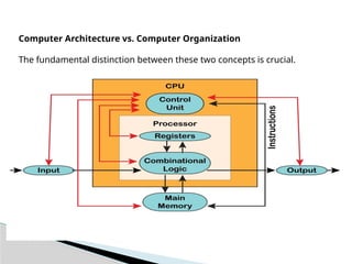
Computer Architecture vs.Computer Organization
The fundamental distinction between these two concepts is crucial.
3.
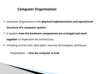
Computer Organizationis the physical implementation and operational
structure of a computer system.
It explains how the hardware components are arranged and work
together to implement the architecture,.
including control units, data paths, memory technologies, and buses.
Computer Organization
•Organization → How the computer is built
4.
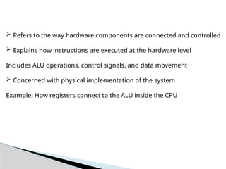
Refers tothe way hardware components are connected and controlled
Explains how instructions are executed at the hardware level
Includes ALU operations, control signals, and data movement
Concerned with physical implementation of the system
Example: How registers connect to the ALU inside the CPU
5.
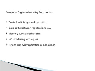
Computer Organization –Key Focus Areas
Control unit design and operation
Data paths between registers and ALU
Memory access mechanisms
I/O interfacing techniques
Timing and synchronization of operations
6.
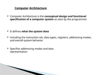
Computer Architectureis the conceptual design and functional
specification of a computer system as seen by the programmer.
It defines what the system does
including the instruction set, data types, registers, addressing modes,
and overall system behavior.
Specifies addressing modes and data
representation
Computer Architecture
7.
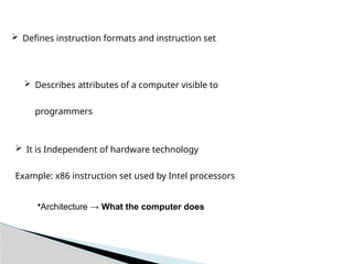
It isIndependent of hardware technology
Example: x86 instruction set used by Intel processors
Defines instruction formats and instruction set
Describes attributes of a computer visible to
programmers
•Architecture → What the computer does
8.
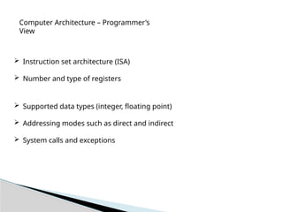
Computer Architecture –Programmer’s
View
Instruction set architecture (ISA)
Number and type of registers
Supported data types (integer, floating point)
Addressing modes such as direct and indirect
System calls and exceptions
9.
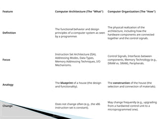
Feature Computer Architecture(The "What") Computer Organization (The "How")
Definition
The functional behavior and design
principles of a computer system as seen
by a programmer.
The physical realization of the
architecture, including how the
hardware components are connected
together and the control signals.
Focus
Instruction Set Architecture (ISA),
Addressing Modes, Data Types,
Memory Addressing Techniques, I/O
Mechanisms.
Control Signals, Interfaces between
components, Memory Technology (e.g.,
DRAM vs. SRAM), Peripherals.
Analogy
The blueprint of a house (the design
and functionality).
The construction of the house (the
selection and connection of materials).
Change
Does not change often (e.g., the x86
instruction set is constant).
May change frequently (e.g., upgrading
from a hardwired control unit to a
microprogrammed one).
10.
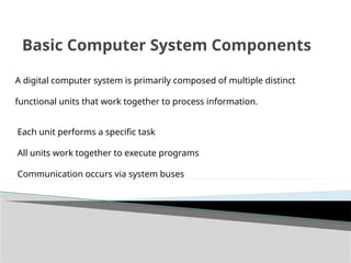
Basic Computer SystemComponents
A digital computer system is primarily composed of multiple distinct
functional units that work together to process information.
Each unit performs a specific task
All units work together to execute programs
Communication occurs via system buses
11.
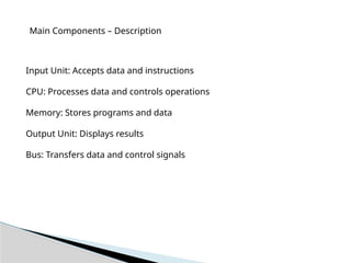
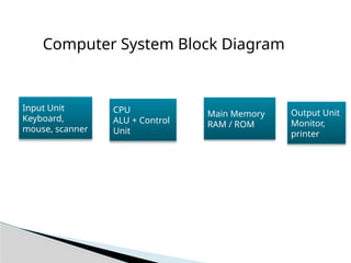
Main Components –Description
Input Unit: Accepts data and instructions
CPU: Processes data and controls operations
Memory: Stores programs and data
Output Unit: Displays results
Bus: Transfers data and control signals
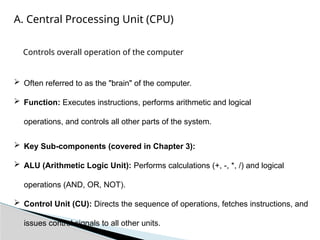
A. Central ProcessingUnit (CPU)
Often referred to as the "brain" of the computer.
Function: Executes instructions, performs arithmetic and logical
operations, and controls all other parts of the system.
Key Sub-components (covered in Chapter 3):
ALU (Arithmetic Logic Unit): Performs calculations (+, -, *, /) and logical
operations (AND, OR, NOT).
Control Unit (CU): Directs the sequence of operations, fetches instructions, and
issues control signals to all other units.
Controls overall operation of the computer
14.
Registers: Small,high-speed storage locations within the CPU used to hold
data, addresses, and instructions temporarily during execution.
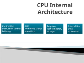
Components of CPU
Arithmetic Logic Unit (ALU)
Control Unit (CU)
Registers
Internal buses
Clock circuitry
15.
CPU Example
Instruction:ADD R1, R2
Operands fetched from registers
ALU performs addition
Result stored back in register
Control unit manages the steps
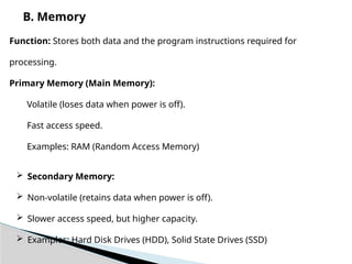
B. Memory
Function: Storesboth data and the program instructions required for
processing.
Primary Memory (Main Memory):
Volatile (loses data when power is off).
Fast access speed.
Examples: RAM (Random Access Memory)
Secondary Memory:
Non-volatile (retains data when power is off).
Slower access speed, but higher capacity.
Examples: Hard Disk Drives (HDD), Solid State Drives (SSD)
18.
Memory storesdata and instructions
Provides data to CPU during execution
Speed of memory affects performance
Different types exist based on speed and cost
Memory System
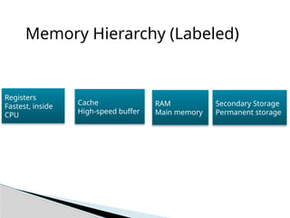
19.
Types of Memory
Registers – fastest, smallest
Cache memory – high-speed buffer
Main memory – RAM
Secondary memory – HDD, SSD
Non-volatile vs volatile memory
20.
Memory Example
Programloaded from disk to RAM
Instructions copied to cache
Registers hold operands
CPU executes instruction
Result written back to memory
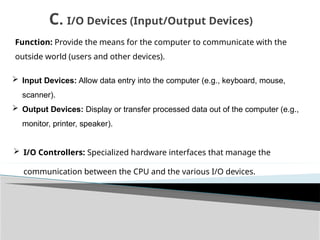
Function: Provide themeans for the computer to communicate with the
outside world (users and other devices).
Input Devices: Allow data entry into the computer (e.g., keyboard, mouse,
scanner).
Output Devices: Display or transfer processed data out of the computer (e.g.,
monitor, printer, speaker).
C. I/O Devices (Input/Output Devices)
I/O Controllers: Specialized hardware interfaces that manage the
communication between the CPU and the various I/O devices.
23.
Input and OutputDevices
Enable interaction with external environment
Input devices supply data
Output devices present results
Controlled using I/O modules
Slower than CPU operations
24.
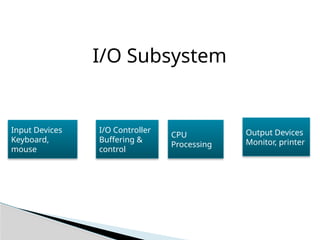
I/O Example
Keyboard sendsdata to CPU
I/O controller buffers input
CPU processes data
Result sent to monitor
D. Buses
Function:A set of electrical conductors (wires) that
interconnect the major components of the computer system,
enabling the transfer of data and control signals.
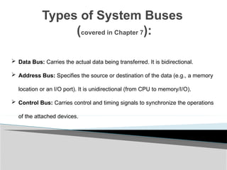
Types of SystemBuses
(covered in Chapter 7):
Data Bus: Carries the actual data being transferred. It is bidirectional.
Address Bus: Specifies the source or destination of the data (e.g., a memory
location or an I/O port). It is unidirectional (from CPU to memory/I/O).
Control Bus: Carries control and timing signals to synchronize the operations
of the attached devices.
29.
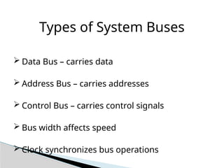
Types of SystemBuses
Data Bus – carries data
Address Bus – carries addresses
Control Bus – carries control signals
Bus width affects speed
Clock synchronizes bus operations
30.
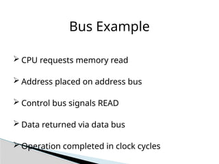
Bus Example
CPUrequests memory read
Address placed on address bus
Control bus signals READ
Data returned via data bus
Operation completed in clock cycles
31.
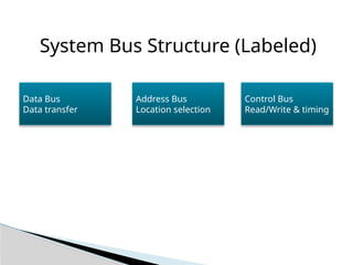
System Bus Structure(Labeled)
Data Bus
Data transfer
Address Bus
Location selection
Control Bus
Read/Write & timing