The document discusses signals carried over telecommunications networks. It covers:
1) Different types of information transmitted including voice, video, text, and files with varying bandwidth and loss tolerance requirements.
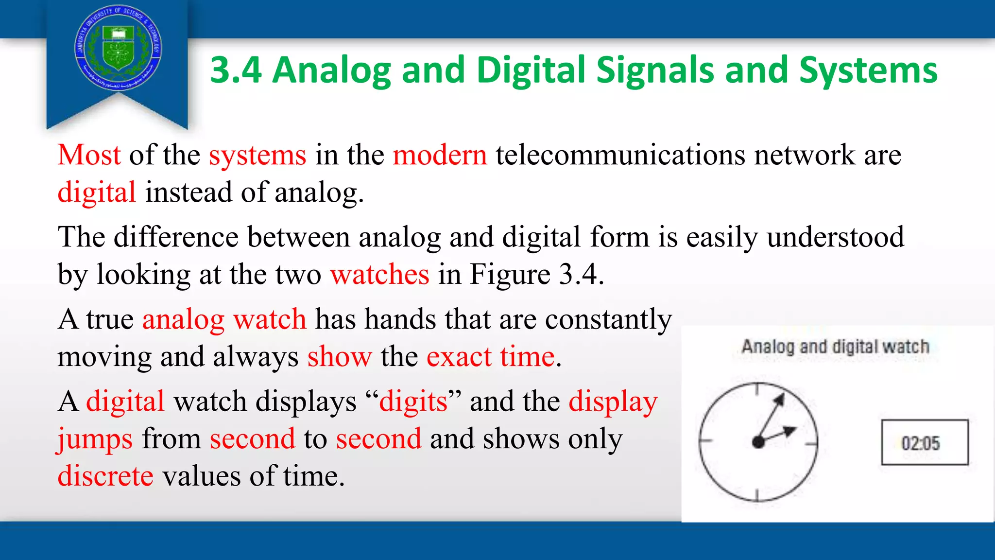
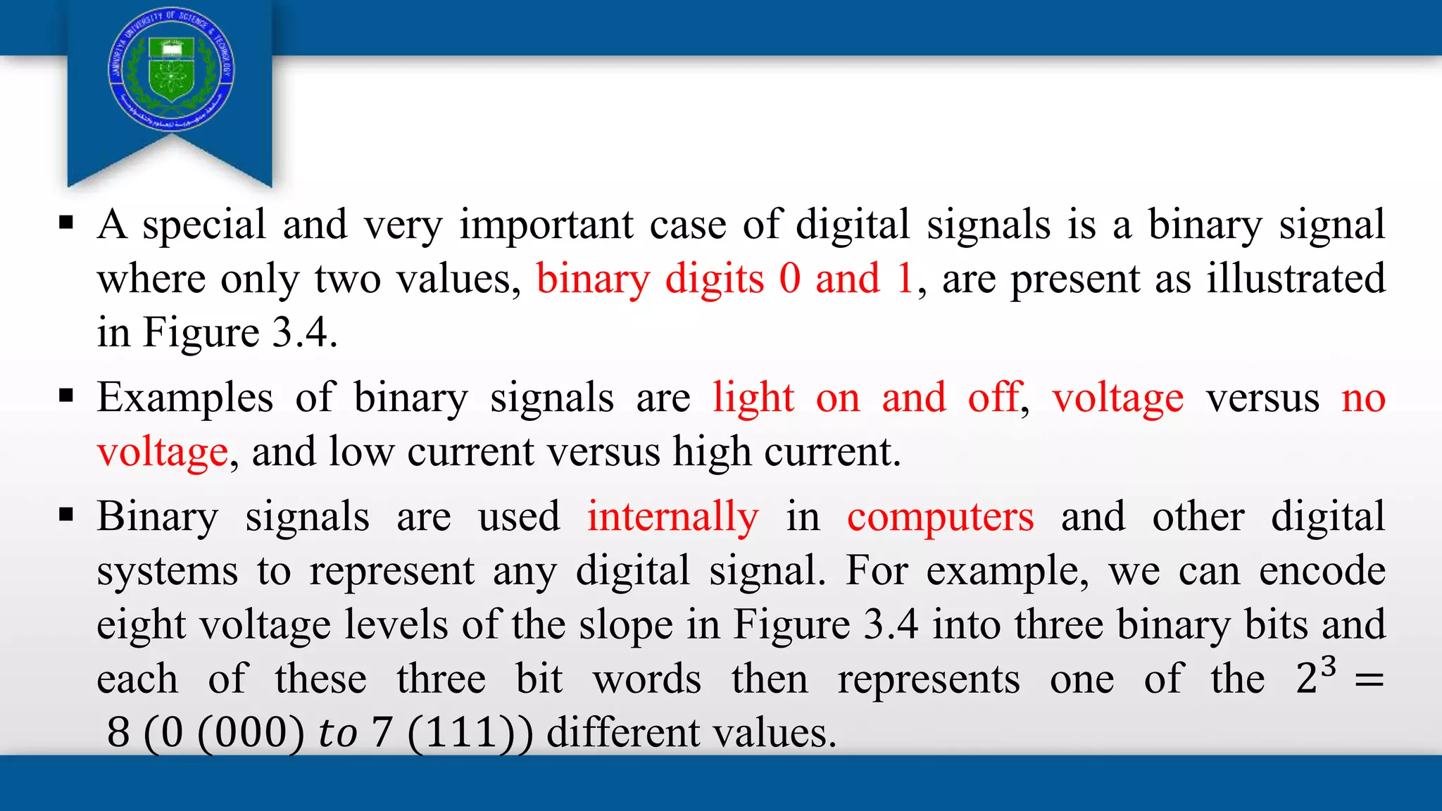
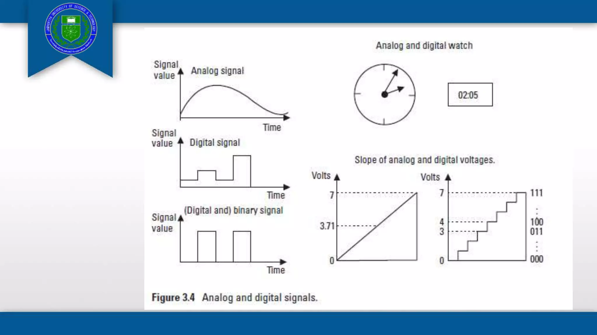
2) Analog and digital signals, with digital transmission becoming more common due to advantages like reliability and cost.
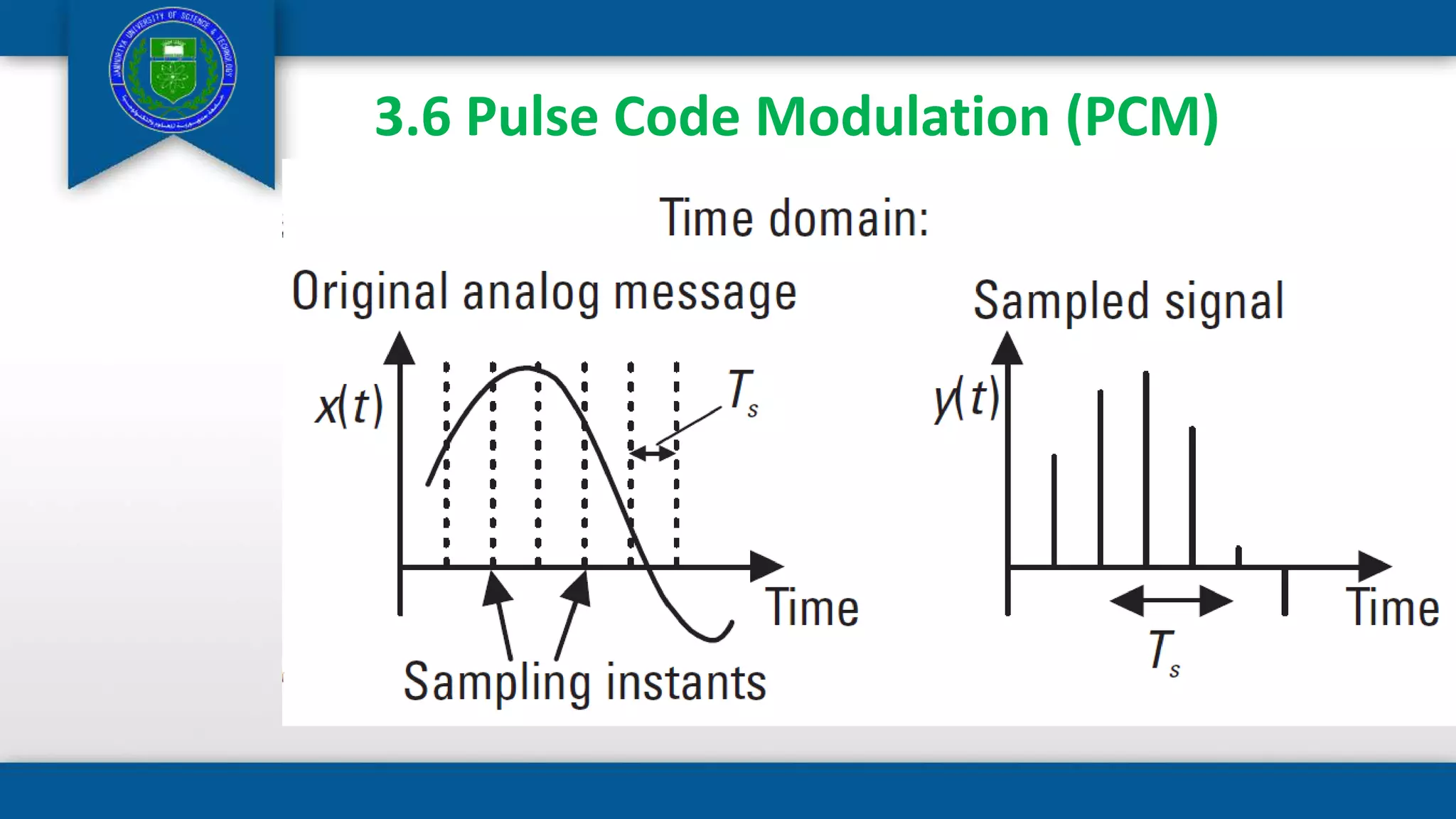
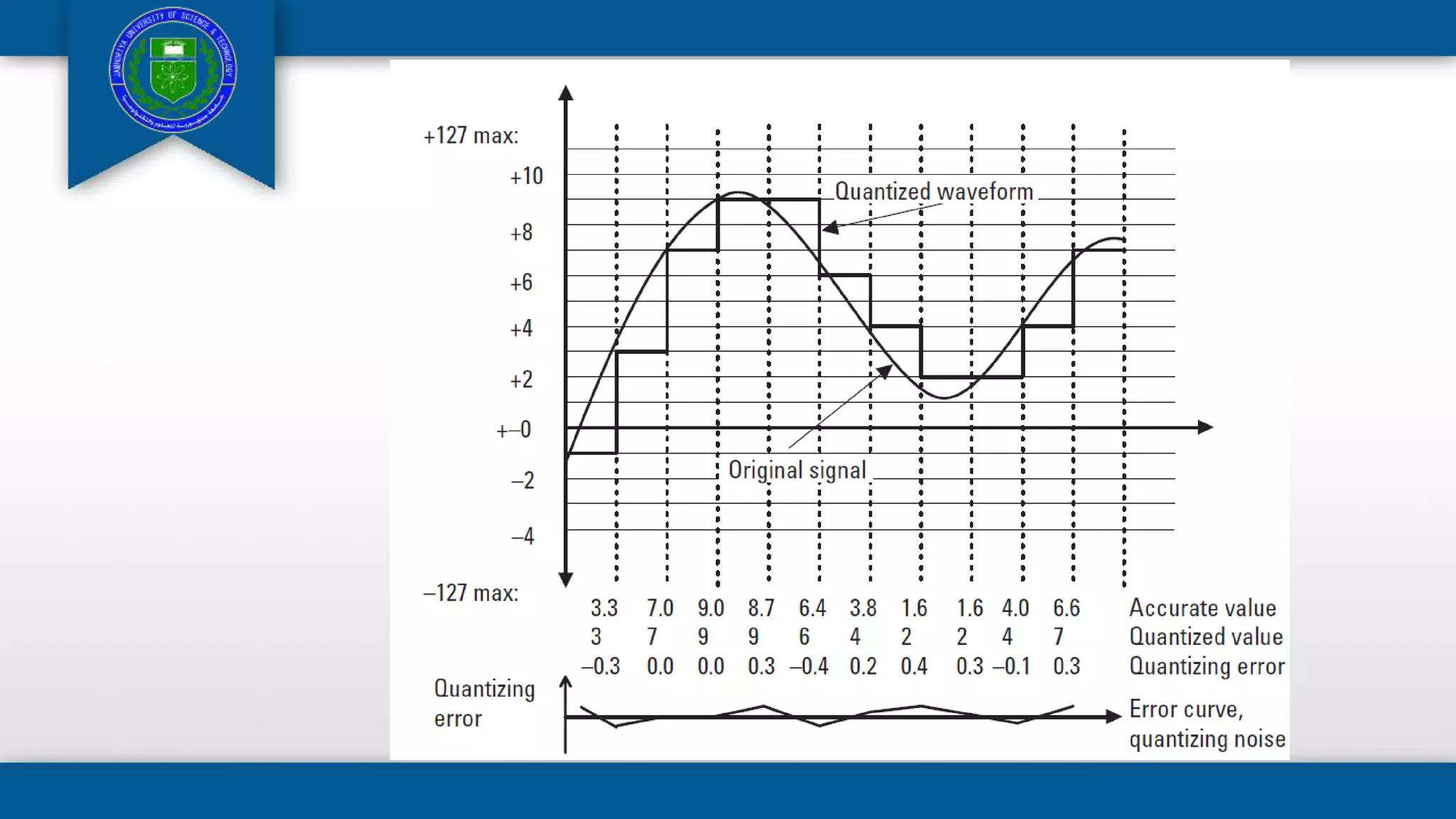
3) Pulse code modulation is introduced as the standardized digital encoding method used in telephone networks to convert analog signals to digital for transmission.