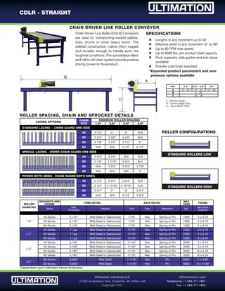
Ultimation Industries LLC
27930 Groesbeck Hw y. Roseville, MI 48066 USA
Copyright 2011
Ultimationinc.com
Telephone +1.586.771.1881
Fax +1.586.771.1882
CDLR - STRAIGHT
Chain Driven Live Roller (CDLR) Conveyors
are ideal for transporting loaded pallets,
tires, drums or other heavy items. The
welded construction makes them rugged
and durable enough to handle even the
toughest conditions. The sprocketed rollers
and roll to roll chain system provide positive
driving power to the product.
SPECIFICATIONS
	n Lengths in any increment up to 50'
n Effective width in any increment 12" to 96"
n Up to 80 FPM max speed
n Up to 6000 lbs. per product load capacity
n Floor supports, side guides and end stops
available
n Powder coat finish standard
Ref. 1.9" 2.5" - 2.6" 3.5"
A 12" - 54" 12" - 64" 12" - 96"
B 3' - 50'
C 12" - 48"
A = Effective Width
B = Overall Length (OAL)
C = Top of Roller (TOR)
ROLLER
DIAMETER
SROCKETS AND
CHAINS
TUBE DETAIL AXLE DETAIL
MAX
LOAD
FRAME
Series
Wall
Thickness
Material Size Type Retention* lbs.
Structural
Channel
1.9"
40 Series 0.145" Mild Steel or Galvanized 7/16" Hex Spring or Pin 1500 5 x 6.7#
50 Series 0.145" Mild Steel or Galvanized 7/16" Hex Spring or Pin 1500 5 x 6.7#
60 Series 0.145" Mild Steel or Galvanized 7/16" Hex Spring or Pin 1500 6 x 8.2#
2.5"
40 Series 11 ga. Mild Steel or Galvanized 11/16" Hex Spring or Pin 2500 5 x 6.7#
50 Series 11 ga. Mild Steel or Galvanized 11/16" Hex Spring or Pin 2500 5 x 6.7#
60 Series 11 ga. Mild Steel or Galvanized 11/16" Hex Spring or Pin 2500 6 x 8.2#
2.6"
40 Series 0.180" Mild Steel or Galvanized 11/16" Hex Spring or Pin 3500 5 x 6.7#
50 Series 0.180" Mild Steel or Galvanized 11/16" Hex Spring or Pin 3500 5 x 6.7#
60 Series 0.180" Mild Steel or Galvanized 11/16" Hex Spring or Pin 3500 6 x 8.2#
80 Series 0.180" Mild Steel or Galvanized 11/16" Hex Spring or Pin 3500 6 x 8.2#
3.5"
60 Series 0.300" Mild Steel 1-1/16" Hex Pin 6000 7 x 9.8#
80 Series 0.300" Mild Steel 1-1/16" Hex Pin 6000 8 x 11.5#
*Dependent upon between frame dimension
LACING OPTIONS
CHAIN
SIZE
MINIMUM ROLLER SPACING
1.9" 2.5" 2.6" 3.5"
STANDARD LACING - CHAIN GUARD ONE SIDE
40 3 1/2" 4" 4" N/A
50 3 3/4" 4 3/8" 4 3/8" N/A
60 4 1/8" 4 1/2" 4 1/2" 6"
80 N/A N/A 5 1/2" 6 1/2"
SPECIAL LACING - WIDER CHAIN GUARD ONE SIDE
40 2 3/4" 3 1/2" N/A N/A
50 3 1/8" 3 7/16" 3 3/4" N/A
60 N/A 3 3/4" 3 3/4" 4 7/8"
80 N/A N/A N/A 5"
POWER BOTH SIDES - CHAIN GUARD BOTH SIDES
40 2 1/4" 2 3/4" 2 3/4" N/A
50 2 1/2" 2 13/16" 2 13/16" N/A
60 2 3/4" 3" 3" 3 3/4"
80 N/A N/A 3 1/4" 3 3/4"
B
C
A
CHAIN DRIVEN LIVE ROLLER CONVEYOR
ROLLER SPACING, CHAIN AND SPROCKET DETAILS
ROLLER CONFIGURATIONS
STANDARD ROLLERS LOW
STANDARD ROLLERS HIGH
*Expanded product parameters and zero
pressure options available
Ultimation Industries LLC
27930 Groesbeck Hw y. Roseville, MI 48066 USA
Copyright 2011
Ultimationinc.com
Telephone +1.586.771.1881
Fax +1.586.771.1882
CDLR - STRAIGHT
ROLLER
PRODUCT
WEIGHT
UP TO 10' UP TO 20' UP TO 30' UP TO 40' UP TO 50'
2 PRODUCTS 4 PRODUCTS 6 PRODUCTS 8 PRODUCTS 10 PRODUCTS
30 FPM 45 FPM 60 FPM 30 FPM 45 FPM 60 FPM 30 FPM 45 FPM 60 FPM 30 FPM 45 FPM 60 FPM 30 FPM 45 FPM 60 FPM
1.9
500 1/2 1/2 1/2 1/2 1/2 1/2 1/2 1/2 3/4 1/2 3/4 1 3/4 1 1-1/2
1000 1/2 1/2 3/4 1/2 3/4 3/4 3/4 1 1-1/2 3/4 1-1/2 1-1/2 1 1-1/2 2
2.5
2000 1/2 3/4 3/4 3/4 1-1/2 1-1/2 1-1/2 2 N/A 1-1/2
2500 1/2 3/4 1 1 1-1/2 2 1-1/2 2
2.6
3000 3/4 1 1-1/2 1-1/2 2 N/A 2
3500 3/4 1 1-1/2 1-1/2 2
3.5
4000 1 1-1/2 1-1/2 2
6000 1-1/2 2
GENERAL HP GUIDELINES
DRIVE MOUNTING OPTIONS AVAILABLE
DRIVE MOUNTED LOW DRIVE MOUNTED HIGH DRIVE MOUNTED UNDERHUNG
208-230/460VAC - 3 PHASE - 60 Hz
	n Totally enclosed fan cooled
n 1750 RPM
n Inverter capable 4:1 speed ratio
n 1.00 service factor
n Sealed worm gear “C” face speed reducer
115/230VAC - 1 PHASE - 60 Hz
n Totally enclosed fan cooled
n 1750 RPM
n 1.15 service factor
n Sealed worm gear “C” face speed reducer LEFT END CENTER RIGHT END
ROLLER CAPACITY INFORMATION
The Maximum Roller Capacity chart is designed to help
determine the size of the roller required for a given load
and length. Use only 2/3 of the rollers under the product
when calculating the required roller capacity because the
conveying surface of products may not always be flat.
NON-PRECISION BEARING (NP)
Non-Precision bearings are made of a stamped metal
housing with very loose tolerances. They are not
intended for very heavy loads or high speeds.
PRECISION BEARINGS (P)
Precision Bearings are made from high quality steel,
heat treated to uniform hardness and ground to a
micro finish. The tolerances are much tighter than
semi-precision bearings making them capable of
greater speeds and load capacities but sensitive to
axle deflection causing misalignment.
- Multiple drives or conveyor sections may be needed to meet your
application capacity/speed requirements
- Other roller, speed and horsepower combinations are available
DRIVE SPECIFICATIONS

Cdlr straight specs

  • 1.
    Ultimation Industries LLC 27930Groesbeck Hw y. Roseville, MI 48066 USA Copyright 2011 Ultimationinc.com Telephone +1.586.771.1881 Fax +1.586.771.1882 CDLR - STRAIGHT Chain Driven Live Roller (CDLR) Conveyors are ideal for transporting loaded pallets, tires, drums or other heavy items. The welded construction makes them rugged and durable enough to handle even the toughest conditions. The sprocketed rollers and roll to roll chain system provide positive driving power to the product. SPECIFICATIONS n Lengths in any increment up to 50' n Effective width in any increment 12" to 96" n Up to 80 FPM max speed n Up to 6000 lbs. per product load capacity n Floor supports, side guides and end stops available n Powder coat finish standard Ref. 1.9" 2.5" - 2.6" 3.5" A 12" - 54" 12" - 64" 12" - 96" B 3' - 50' C 12" - 48" A = Effective Width B = Overall Length (OAL) C = Top of Roller (TOR) ROLLER DIAMETER SROCKETS AND CHAINS TUBE DETAIL AXLE DETAIL MAX LOAD FRAME Series Wall Thickness Material Size Type Retention* lbs. Structural Channel 1.9" 40 Series 0.145" Mild Steel or Galvanized 7/16" Hex Spring or Pin 1500 5 x 6.7# 50 Series 0.145" Mild Steel or Galvanized 7/16" Hex Spring or Pin 1500 5 x 6.7# 60 Series 0.145" Mild Steel or Galvanized 7/16" Hex Spring or Pin 1500 6 x 8.2# 2.5" 40 Series 11 ga. Mild Steel or Galvanized 11/16" Hex Spring or Pin 2500 5 x 6.7# 50 Series 11 ga. Mild Steel or Galvanized 11/16" Hex Spring or Pin 2500 5 x 6.7# 60 Series 11 ga. Mild Steel or Galvanized 11/16" Hex Spring or Pin 2500 6 x 8.2# 2.6" 40 Series 0.180" Mild Steel or Galvanized 11/16" Hex Spring or Pin 3500 5 x 6.7# 50 Series 0.180" Mild Steel or Galvanized 11/16" Hex Spring or Pin 3500 5 x 6.7# 60 Series 0.180" Mild Steel or Galvanized 11/16" Hex Spring or Pin 3500 6 x 8.2# 80 Series 0.180" Mild Steel or Galvanized 11/16" Hex Spring or Pin 3500 6 x 8.2# 3.5" 60 Series 0.300" Mild Steel 1-1/16" Hex Pin 6000 7 x 9.8# 80 Series 0.300" Mild Steel 1-1/16" Hex Pin 6000 8 x 11.5# *Dependent upon between frame dimension LACING OPTIONS CHAIN SIZE MINIMUM ROLLER SPACING 1.9" 2.5" 2.6" 3.5" STANDARD LACING - CHAIN GUARD ONE SIDE 40 3 1/2" 4" 4" N/A 50 3 3/4" 4 3/8" 4 3/8" N/A 60 4 1/8" 4 1/2" 4 1/2" 6" 80 N/A N/A 5 1/2" 6 1/2" SPECIAL LACING - WIDER CHAIN GUARD ONE SIDE 40 2 3/4" 3 1/2" N/A N/A 50 3 1/8" 3 7/16" 3 3/4" N/A 60 N/A 3 3/4" 3 3/4" 4 7/8" 80 N/A N/A N/A 5" POWER BOTH SIDES - CHAIN GUARD BOTH SIDES 40 2 1/4" 2 3/4" 2 3/4" N/A 50 2 1/2" 2 13/16" 2 13/16" N/A 60 2 3/4" 3" 3" 3 3/4" 80 N/A N/A 3 1/4" 3 3/4" B C A CHAIN DRIVEN LIVE ROLLER CONVEYOR ROLLER SPACING, CHAIN AND SPROCKET DETAILS ROLLER CONFIGURATIONS STANDARD ROLLERS LOW STANDARD ROLLERS HIGH *Expanded product parameters and zero pressure options available
  • 2.
    Ultimation Industries LLC 27930Groesbeck Hw y. Roseville, MI 48066 USA Copyright 2011 Ultimationinc.com Telephone +1.586.771.1881 Fax +1.586.771.1882 CDLR - STRAIGHT ROLLER PRODUCT WEIGHT UP TO 10' UP TO 20' UP TO 30' UP TO 40' UP TO 50' 2 PRODUCTS 4 PRODUCTS 6 PRODUCTS 8 PRODUCTS 10 PRODUCTS 30 FPM 45 FPM 60 FPM 30 FPM 45 FPM 60 FPM 30 FPM 45 FPM 60 FPM 30 FPM 45 FPM 60 FPM 30 FPM 45 FPM 60 FPM 1.9 500 1/2 1/2 1/2 1/2 1/2 1/2 1/2 1/2 3/4 1/2 3/4 1 3/4 1 1-1/2 1000 1/2 1/2 3/4 1/2 3/4 3/4 3/4 1 1-1/2 3/4 1-1/2 1-1/2 1 1-1/2 2 2.5 2000 1/2 3/4 3/4 3/4 1-1/2 1-1/2 1-1/2 2 N/A 1-1/2 2500 1/2 3/4 1 1 1-1/2 2 1-1/2 2 2.6 3000 3/4 1 1-1/2 1-1/2 2 N/A 2 3500 3/4 1 1-1/2 1-1/2 2 3.5 4000 1 1-1/2 1-1/2 2 6000 1-1/2 2 GENERAL HP GUIDELINES DRIVE MOUNTING OPTIONS AVAILABLE DRIVE MOUNTED LOW DRIVE MOUNTED HIGH DRIVE MOUNTED UNDERHUNG 208-230/460VAC - 3 PHASE - 60 Hz n Totally enclosed fan cooled n 1750 RPM n Inverter capable 4:1 speed ratio n 1.00 service factor n Sealed worm gear “C” face speed reducer 115/230VAC - 1 PHASE - 60 Hz n Totally enclosed fan cooled n 1750 RPM n 1.15 service factor n Sealed worm gear “C” face speed reducer LEFT END CENTER RIGHT END ROLLER CAPACITY INFORMATION The Maximum Roller Capacity chart is designed to help determine the size of the roller required for a given load and length. Use only 2/3 of the rollers under the product when calculating the required roller capacity because the conveying surface of products may not always be flat. NON-PRECISION BEARING (NP) Non-Precision bearings are made of a stamped metal housing with very loose tolerances. They are not intended for very heavy loads or high speeds. PRECISION BEARINGS (P) Precision Bearings are made from high quality steel, heat treated to uniform hardness and ground to a micro finish. The tolerances are much tighter than semi-precision bearings making them capable of greater speeds and load capacities but sensitive to axle deflection causing misalignment. - Multiple drives or conveyor sections may be needed to meet your application capacity/speed requirements - Other roller, speed and horsepower combinations are available DRIVE SPECIFICATIONS