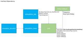
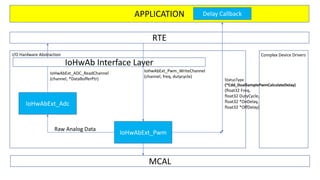
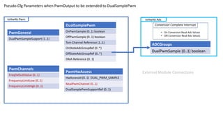
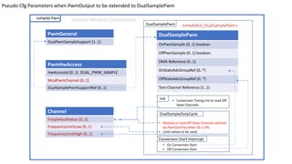
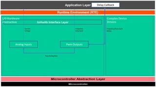
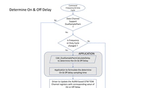
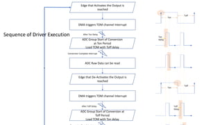
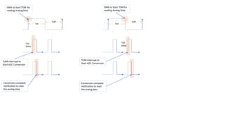
IoHwAbExt_Adc
IoHwAbExt_Pwm Cdd
Delay Callback
Raw Analog Data
Frequency
Duty Cycle Delays
StatusType (*Cdd_DualSamplePwmCalculateDelay)
(IoHwAbExt_Pwm_ChannelType channel,
float32 Freq,
float32 DutyCycle,
float32 *OnDelay,
float32 *OffDelay)
Std_ReturnType Cdd_Xxx_ReadFbCurrent
(float32* Current);
IoHwAbExt_BD16952
Interface-Dependency
IoHwAbExt_Adc
IoHwAbExt_Pwm
StatusType
(*Cdd_DualSamplePwmCalculateDelay)
(float32 Freq,
float32 DutyCycle,
float32 *OnDelay,
float32 *OffDelay)
APPLICATION
RTE
I/O Hardware Abstraction Complex Device Drivers
IoHwAb Interface Layer
MCAL
IoHwAbExt_ADC_ReadChannel
(channel, *DataBufferPtr)
Raw Analog Data
IoHwAbExt_Pwm_WriteChannel
(channel, freq, dutycycle)
Delay Callback
IoHwAb Adc
ADCGroups
DualPwmSample (0..1) boolean
Conversion Complete Interrupt
• On Conversion Read Adc Values
• Off Conversion Read Adc Values
PwmChannels
FreqDefaultValue (0..1)
FrequencyLimitLow (0..1)
FrequencyLimitHigh (0..1)
IoHwAb Pwm
PwmGeneral
DualPwmSampleSupport (1..1)
DualSamplePwm
OnPwmSample (0..1) boolean
OffPwmSample (0..1) boolean
Tom Channel Reference (1..1)
OnStateAdcGroupRef (0..*)
OffStateAdcGroupRef (0..*)
DMA Reference (0..1)
Pseudo Cfg Parameters when PwmOutput to be extended to DualSamplePwm
External Module Connections
PwmHwAccess
HwAccessId (0..1) DUAL_PWM_SAMPLE
McalPwmChannel (0..1)
DualSamplePwmSupportRef (0..1)
Channel
FreqDefaultValue (0..1)
FrequencyLimitLow (0..1)
FrequencyLimitHigh (0..1)
IoHwAb Pwm
DualSamplePwm
PwmGeneral
DualPwmSampleSupport (1..1)
DualSamplePwm
OnPwmSample (0..1) boolean
OffPwmSample (0..1) boolean
DMA Reference (0..1)
OnStateAdcGroupRef (0..*)
OffStateAdcGroupRef (0..*)
Tom Channel Reference (1..1)
Pseudo Cfg Parameters when PwmOutput to be extended to DualSamplePwm
Internal Module Connections
Init • Conversion Timing Init to read Off
State Channels
DualSampleDutyCycle
• Module to read Off State Channels defined
by PwmOutFreq when DC is 0%
• Limit values to be used
Conversion Start Interrupt
• On Conversion Start
• Off Conversion Start
PwmHwAccess
HwAccessId (0..1) DUAL_PWM_SAMPLE
McalPwmChannel (0..1)
DualSamplePwmSupportRef (0..1)
IoHwAbExt_DualSamplePwm.c
I/O Hardware
Abstraction
Complex Device
Drivers
IoHwAb Interface Layer
Analog Inputs Pwm Outputs
Current
Voltage
Frequency
Duty Cycle
Delay Callback
Frequency/Duty Cycle
Delays
Raw Analog Data
Determine On & Off Delay
Command
Frequency & Duty
Cycle
Cdd_DualSamplePwmCalculateDelay
to determine the On & Off Delay
Is Frequency
or Duty Cycle
changed ?
Yes
Application to formulate the determine
On & Off delay sampling time
Driver to Update the AURIX based GTM TOM
Channel registers with corresponding value of
On or Off Delay
APPLICATION
No
Does Channel
Support
DualSamplePwm
?
Yes
No
Sequence of Driver Execution
DMA triggers TOM channel Interrupt
ADC Group Start of Conversion
at Ton Period
Load TOM with Toff delay
After Ton Delay
ADC Raw Data can be read
Conversion Complete Interrupt
ADC Group Start of Conversion at
Toff Period
Load TOM with Ton delay
After Toff Delay
Edge that Activates the Output is
reached
Edge that De-Activates the Output is
reached
DMA triggers TOM channel Interrupt
Ton
Toff
Ton
Toff
Ton
Delay
Toff
Delay
Ton
Toff
Ton
Delay
DMA to Start TOM for
reading Analog Data
TOM Interrupt to
Start ADC Conversion
Conversion complete
notification to read
the analog data
Ton
Toff
Toff
Delay
DMA to Start TOM for
reading Analog Data
TOM Interrupt to
Start ADC Conversion
Conversion complete
notification to read
the analog data

Cdd Dual Sample Pulse width modulation Flow Chart Diagram.pptx

  • 1.
    IoHwAbExt_Adc IoHwAbExt_Pwm Cdd Delay Callback RawAnalog Data Frequency Duty Cycle Delays StatusType (*Cdd_DualSamplePwmCalculateDelay) (IoHwAbExt_Pwm_ChannelType channel, float32 Freq, float32 DutyCycle, float32 *OnDelay, float32 *OffDelay) Std_ReturnType Cdd_Xxx_ReadFbCurrent (float32* Current); IoHwAbExt_BD16952 Interface-Dependency
  • 2.
    IoHwAbExt_Adc IoHwAbExt_Pwm StatusType (*Cdd_DualSamplePwmCalculateDelay) (float32 Freq, float32 DutyCycle, float32*OnDelay, float32 *OffDelay) APPLICATION RTE I/O Hardware Abstraction Complex Device Drivers IoHwAb Interface Layer MCAL IoHwAbExt_ADC_ReadChannel (channel, *DataBufferPtr) Raw Analog Data IoHwAbExt_Pwm_WriteChannel (channel, freq, dutycycle) Delay Callback
  • 3.
    IoHwAb Adc ADCGroups DualPwmSample (0..1)boolean Conversion Complete Interrupt • On Conversion Read Adc Values • Off Conversion Read Adc Values PwmChannels FreqDefaultValue (0..1) FrequencyLimitLow (0..1) FrequencyLimitHigh (0..1) IoHwAb Pwm PwmGeneral DualPwmSampleSupport (1..1) DualSamplePwm OnPwmSample (0..1) boolean OffPwmSample (0..1) boolean Tom Channel Reference (1..1) OnStateAdcGroupRef (0..*) OffStateAdcGroupRef (0..*) DMA Reference (0..1) Pseudo Cfg Parameters when PwmOutput to be extended to DualSamplePwm External Module Connections PwmHwAccess HwAccessId (0..1) DUAL_PWM_SAMPLE McalPwmChannel (0..1) DualSamplePwmSupportRef (0..1)
  • 4.
    Channel FreqDefaultValue (0..1) FrequencyLimitLow (0..1) FrequencyLimitHigh(0..1) IoHwAb Pwm DualSamplePwm PwmGeneral DualPwmSampleSupport (1..1) DualSamplePwm OnPwmSample (0..1) boolean OffPwmSample (0..1) boolean DMA Reference (0..1) OnStateAdcGroupRef (0..*) OffStateAdcGroupRef (0..*) Tom Channel Reference (1..1) Pseudo Cfg Parameters when PwmOutput to be extended to DualSamplePwm Internal Module Connections Init • Conversion Timing Init to read Off State Channels DualSampleDutyCycle • Module to read Off State Channels defined by PwmOutFreq when DC is 0% • Limit values to be used Conversion Start Interrupt • On Conversion Start • Off Conversion Start PwmHwAccess HwAccessId (0..1) DUAL_PWM_SAMPLE McalPwmChannel (0..1) DualSamplePwmSupportRef (0..1) IoHwAbExt_DualSamplePwm.c
  • 5.
    I/O Hardware Abstraction Complex Device Drivers IoHwAbInterface Layer Analog Inputs Pwm Outputs Current Voltage Frequency Duty Cycle Delay Callback Frequency/Duty Cycle Delays Raw Analog Data
  • 6.
    Determine On &Off Delay Command Frequency & Duty Cycle Cdd_DualSamplePwmCalculateDelay to determine the On & Off Delay Is Frequency or Duty Cycle changed ? Yes Application to formulate the determine On & Off delay sampling time Driver to Update the AURIX based GTM TOM Channel registers with corresponding value of On or Off Delay APPLICATION No Does Channel Support DualSamplePwm ? Yes No
  • 7.
    Sequence of DriverExecution DMA triggers TOM channel Interrupt ADC Group Start of Conversion at Ton Period Load TOM with Toff delay After Ton Delay ADC Raw Data can be read Conversion Complete Interrupt ADC Group Start of Conversion at Toff Period Load TOM with Ton delay After Toff Delay Edge that Activates the Output is reached Edge that De-Activates the Output is reached DMA triggers TOM channel Interrupt Ton Toff Ton Toff Ton Delay Toff Delay
  • 8.
    Ton Toff Ton Delay DMA to StartTOM for reading Analog Data TOM Interrupt to Start ADC Conversion Conversion complete notification to read the analog data Ton Toff Toff Delay DMA to Start TOM for reading Analog Data TOM Interrupt to Start ADC Conversion Conversion complete notification to read the analog data