More Related Content
Similar to Lab 9 instructions (20)
Lab 9 instructions
- 1. © 2013 Cisco and/or its affiliates. All rights reserved. This document is Cisco Public. Page 1 of 22
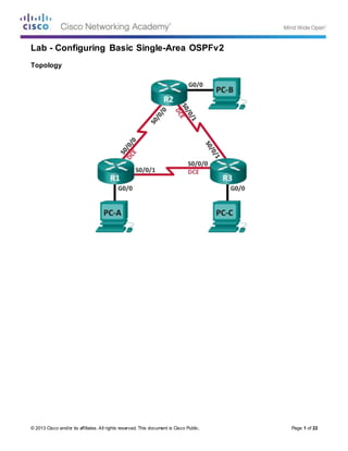
Lab - Configuring Basic Single-Area OSPFv2
Topology
- 2. Lab - Configuring Basic Single-Area OSPFv2
© 2013 Cisco and/or its affiliates. All rights reserved. This document is Cisco Public. Page 2 of 22
Addressing Table
Device Interface IP Address Subnet Mask Default Gateway
R1 G0/0 192.168.1.1 255.255.255.0 N/A
S0/0/0 (DCE) 192.168.12.1 255.255.255.252 N/A
S0/0/1 192.168.13.1 255.255.255.252 N/A
R2 G0/0 192.168.2.1 255.255.255.0 N/A
S0/0/0 192.168.12.2 255.255.255.252 N/A
S0/0/1 (DCE) 192.168.23.1 255.255.255.252 N/A
R3 G0/0 192.168.3.1 255.255.255.0 N/A
S0/0/0 (DCE) 192.168.13.2 255.255.255.252 N/A
S0/0/1 192.168.23.2 255.255.255.252 N/A
PC-A NIC 192.168.1.3 255.255.255.0 192.168.1.1
PC-B NIC 192.168.2.3 255.255.255.0 192.168.2.1
PC-C NIC 192.168.3.3 255.255.255.0 192.168.3.1
Objectives
Part 1: Build the Network and Configure Basic Device Settings
Part 2: Configure and Verify OSPF Routing
Part 3: Change Router ID Assignments
Part 4: Configure OSPF Passive Interfaces
Part 5: Change OSPF Metrics
Background / Scenario
Open Shortest Path First (OSPF) is a link-state routing protocol for IP networks. OSPFv2 is defined for IPv4
networks, and OSPFv3 is defined for IPv6 networks. OSPF detects changes in the topology, such as link
failures, and converges on a new loop-free routing structure very quickly. It computes each route using
Dijkstra’s algorithm, a shortest path first algorithm.
In this lab, you will configure the network topology with OSPFv2 routing, change the router ID assignments,
configure passive interfaces, adjust OSPF metrics, and use a number of CLI commands to display and verify
OSPF routing information.
Note: The routers used with CCNA hands-on labs are Cisco 1941 Integrated Services Routers (ISRs) with
Cisco IOS Release 15.2(4)M3 (universalk9 image). Other routers and Cisco IOS versions can be used.
Depending on the model and Cisco IOS version, the commands available and output produced might vary
from what is shown in the labs. Refer to the Router Interface Summary Table at the end of this lab for the
correct interface identifiers.
Note: Make sure that the routers have been erased and have no startup configurations. If you are unsure,
contact your instructor.
- 3. Lab - Configuring Basic Single-Area OSPFv2
© 2013 Cisco and/or its affiliates. All rights reserved. This document is Cisco Public. Page 3 of 22
Required Resources
3 Routers (Cisco 1941 with Cisco IOS Release 15.2(4)M3 universal image or comparable)
3 PCs (Windows 7, Vista, or XP with terminal emulation program, such as Tera Term)
Console cables to configure the Cisco IOS devices via the console ports
Ethernet and serial cables as shown in the topology
Part 1: Build the Network and Configure Basic DeviceSettings
In Part 1, you set up the network topology and configure basic settings on the PC hosts and routers.
Step 1: Cable the network as shown in the topology.
Step 2: Initialize and reload the routers as necessary.
Step 3: Configure basic settings for each router.
a. Disable DNS lookup.
b. Configure device name as shown in the topology.
c. Assign class as the privileged EXEC password.
d. Assign cisco as the console and vty passwords.
e. Configure a message of the day (MOTD) banner to warn users that unauthorized access is prohibited.
f. Configure logging synchronous for the console line.
g. Configure the IP address listed in the Addressing Table for all interfaces.
h. Set the clock rate for all DCE serial interfaces at 128000.
i. Copy the running configuration to the startup configuration.
Step 4: Configure PC hosts.
Step 5: Test connectivity.
The routers should be able to ping one another, and each PC should be able to ping its default gateway. The
PCs are unable to ping other PCs until OSPF routing is configured. Verify and troubleshoot if necessary.
Part 2: Configureand Verify OSPF Routing
In Part 2, you will configure OSPFv2 routing on all routers in the network and then verify that routing tables
are updated correctly. After OSPF has been verified, you will configure OSPF authentication on the links for
added security.
Step 1: Configure OSPF on R1.
a. Use the router ospf command in global configuration mode to enable OSPF on R1.
R1(config)# router ospf 1
Note: The OSPF process id is kept locally and has no meaning to other routers on the network.
- 4. Lab - Configuring Basic Single-Area OSPFv2
© 2013 Cisco and/or its affiliates. All rights reserved. This document is Cisco Public. Page 4 of 22
b. Configure the network statements for the networks on R1. Use an area ID of 0.
R1(config-router)# network 192.168.1.0 0.0.0.255 area 0
R1(config-router)# network 192.168.12.0 0.0.0.3 area 0
R1(config-router)# network 192.168.13.0 0.0.0.3 area 0
Step 2: Configure OSPF on R2 and R3.
Use the router ospf command and add the network statements for the networks on R2 and R3. Neighbor
adjacency messages display on R1 when OSPF routing is configured on R2 and R3.
R1#
00:22:29: %OSPF-5-ADJCHG: Process 1, Nbr 192.168.23.1 on Serial0/0/0 from LOADING to
FULL, Loading Done
R1#
00:23:14: %OSPF-5-ADJCHG: Process 1, Nbr 192.168.23.2 on Serial0/0/1 from LOADING to
FULL, Loading Done
R1#
Step 3: Verify OSPF neighbors and routing information.
a. Issue the show ip ospf neighbor command to verify that each router lists the other routers in the
network as neighbors.
R1# show ip ospf neighbor
Neighbor ID Pri State Dead Time Address Interface
192.168.23.2 0 FULL/ - 00:00:33 192.168.13.2 Serial0/0/1
192.168.23.1 0 FULL/ - 00:00:30 192.168.12.2 Serial0/0/0
b. Issue the show ip route command to verify that all networks display in the routing table on all routers.
R1# show ip route
Codes: L - local, C - connected, S - static, R - RIP, M - mobile, B - BGP
D - EIGRP, EX - EIGRP external, O - OSPF, IA - OSPF inter area
N1 - OSPF NSSA external type 1, N2 - OSPF NSSA external type 2
E1 - OSPF external type 1, E2 - OSPF external type 2, E - EGP
i - IS-IS, L1 - IS-IS level-1, L2 - IS-IS level-2, ia - IS-IS inter area
* - candidate default, U - per-user static route, o - ODR
P - periodic downloaded static route
Gateway of last resort is not set
192.168.1.0/24 is variably subnetted, 2 subnets, 2 masks
C 192.168.1.0/24 is directly connected, GigabitEthernet0/0
L 192.168.1.1/32 is directly connected, GigabitEthernet0/0
O 192.168.2.0/24 [110/65] via 192.168.12.2, 00:32:33, Serial0/0/0
O 192.168.3.0/24 [110/65] via 192.168.13.2, 00:31:48, Serial0/0/1
192.168.12.0/24 is variably subnetted, 2 subnets, 2 masks
C 192.168.12.0/30 is directly connected, Serial0/0/0
L 192.168.12.1/32 is directly connected, Serial0/0/0
192.168.13.0/24 is variably subnetted, 2 subnets, 2 masks
C 192.168.13.0/30 is directly connected, Serial0/0/1
L 192.168.13.1/32 is directly connected, Serial0/0/1
- 5. Lab - Configuring Basic Single-Area OSPFv2
© 2013 Cisco and/or its affiliates. All rights reserved. This document is Cisco Public. Page 5 of 22
192.168.23.0/30 is subnetted, 1 subnets
O 192.168.23.0/30 [110/128] via 192.168.12.2, 00:31:38, Serial0/0/0
[110/128] via 192.168.13.2, 00:31:38, Serial0/0/1
What command would you use to only see the OSPF routes in the routing table?
_______________________________________________________________________________________
Step 4: Verify OSPF protocol settings.
The show ip protocols command is a quick way to verify vital OSPF configuration information. This
information includes the OSPF process ID, the router ID, networks the router is advertising, the neighbors the
router is receiving updates from, and the default administrative distance, which is 110 for OSPF.
R1# show ip protocols
*** IP Routing is NSF aware ***
Routing Protocol is "ospf 1"
Outgoing update filter list for all interfaces is not set
Incoming update filter list for all interfaces is not set
Router ID 192.168.13.1
Number of areas in this router is 1. 1 normal 0 stub 0 nssa
Maximum path: 4
Routing for Networks:
192.168.1.0 0.0.0.255 area 0
192.168.12.0 0.0.0.3 area 0
192.168.13.0 0.0.0.3 area 0
Routing Information Sources:
Gateway Distance Last Update
192.168.23.2 110 00:19:16
192.168.23.1 110 00:20:03
Distance: (default is 110)
Step 5: Verify OSPF process information.
Use the show ip ospf command to examine the OSPF process ID and router ID. This command displays the
OSPF area information, as well as the last time the SPF algorithm was calculated.
R1# show ip ospf
Routing Process "ospf 1" with ID 192.168.13.1
Start time: 00:20:23.260, Time elapsed: 00:25:08.296
Supports only single TOS(TOS0) routes
Supports opaque LSA
Supports Link-local Signaling (LLS)
Supports area transit capability
Supports NSSA (compatible with RFC 3101)
Event-log enabled, Maximum number of events: 1000, Mode: cyclic
Router is not originating router-LSAs with maximum metric
Initial SPF schedule delay 5000 msecs
Minimum hold time between two consecutive SPFs 10000 msecs
Maximum wait time between two consecutive SPFs 10000 msecs
Incremental-SPF disabled
Minimum LSA interval 5 secs
- 6. Lab - Configuring Basic Single-Area OSPFv2
© 2013 Cisco and/or its affiliates. All rights reserved. This document is Cisco Public. Page 6 of 22
Minimum LSA arrival 1000 msecs
LSA group pacing timer 240 secs
Interface flood pacing timer 33 msecs
Retransmission pacing timer 66 msecs
Number of external LSA 0. Checksum Sum 0x000000
Number of opaque AS LSA 0. Checksum Sum 0x000000
Number of DCbitless external and opaque AS LSA 0
Number of DoNotAge external and opaque AS LSA 0
Number of areas in this router is 1. 1 normal 0 stub 0 nssa
Number of areas transit capable is 0
External flood list length 0
IETF NSF helper support enabled
Cisco NSF helper support enabled
Reference bandwidth unit is 100 mbps
Area BACKBONE(0)
Number of interfaces in this area is 3
Area has no authentication
SPF algorithm last executed 00:22:53.756 ago
SPF algorithm executed 7 times
Area ranges are
Number of LSA 3. Checksum Sum 0x019A61
Number of opaque link LSA 0. Checksum Sum 0x000000
Number of DCbitless LSA 0
Number of indication LSA 0
Number of DoNotAge LSA 0
Flood list length 0
Step 6: Verify OSPF interface settings.
a. Issue the show ip ospf interface brief command to display a summary of OSPF-enabled interfaces.
R1# show ip ospf interface brief
Interface PID Area IP Address/Mask Cost State Nbrs F/C
Se0/0/1 1 0 192.168.13.1/30 64 P2P 1/1
Se0/0/0 1 0 192.168.12.1/30 64 P2P 1/1
Gi0/0 1 0 192.168.1.1/24 1 DR 0/0
b. For a more detailed list of every OSPF-enabled interface, issue the show ip ospf interface command.
R1# show ip ospf interface
Serial0/0/1 is up, line protocol is up
Internet Address 192.168.13.1/30, Area 0, Attached via Network Statement
Process ID 1, Router ID 192.168.13.1, Network Type POINT_TO_POINT, Cost: 64
Topology-MTID Cost Disabled Shutdown Topology Name
0 64 no no Base
Transmit Delay is 1 sec, State POINT_TO_POINT
Timer intervals configured, Hello 10, Dead 40, Wait 40, Retransmit 5
oob-resync timeout 40
Hello due in 00:00:01
Supports Link-local Signaling (LLS)
Cisco NSF helper support enabled
IETF NSF helper support enabled
- 7. Lab - Configuring Basic Single-Area OSPFv2
© 2013 Cisco and/or its affiliates. All rights reserved. This document is Cisco Public. Page 7 of 22
Index 3/3, flood queue length 0
Next 0x0(0)/0x0(0)
Last flood scan length is 1, maximum is 1
Last flood scan time is 0 msec, maximum is 0 msec
Neighbor Count is 1, Adjacent neighbor count is 1
Adjacent with neighbor 192.168.23.2
Suppress hello for 0 neighbor(s)
Serial0/0/0 is up, line protocol is up
Internet Address 192.168.12.1/30, Area 0, Attached via Network Statement
Process ID 1, Router ID 192.168.13.1, Network Type POINT_TO_POINT, Cost: 64
Topology-MTID Cost Disabled Shutdown Topology Name
0 64 no no Base
Transmit Delay is 1 sec, State POINT_TO_POINT
Timer intervals configured, Hello 10, Dead 40, Wait 40, Retransmit 5
oob-resync timeout 40
Hello due in 00:00:03
Supports Link-local Signaling (LLS)
Cisco NSF helper support enabled
IETF NSF helper support enabled
Index 2/2, flood queue length 0
Next 0x0(0)/0x0(0)
Last flood scan length is 1, maximum is 1
Last flood scan time is 0 msec, maximum is 0 msec
Neighbor Count is 1, Adjacent neighbor count is 1
Adjacent with neighbor 192.168.23.1
Suppress hello for 0 neighbor(s)
GigabitEthernet0/0 is up, line protocol is up
Internet Address 192.168.1.1/24, Area 0, Attached via Network Statement
Process ID 1, Router ID 192.168.13.1, Network Type BROADCAST, Cost: 1
Topology-MTID Cost Disabled Shutdown Topology Name
0 1 no no Base
Transmit Delay is 1 sec, State DR, Priority 1
Designated Router (ID) 192.168.13.1, Interface address 192.168.1.1
No backup designated router on this network
Timer intervals configured, Hello 10, Dead 40, Wait 40, Retransmit 5
oob-resync timeout 40
Hello due in 00:00:01
Supports Link-local Signaling (LLS)
Cisco NSF helper support enabled
IETF NSF helper support enabled
Index 1/1, flood queue length 0
Next 0x0(0)/0x0(0)
Last flood scan length is 0, maximum is 0
Last flood scan time is 0 msec, maximum is 0 msec
Neighbor Count is 0, Adjacent neighbor count is 0
Suppress hello for 0 neighbor(s)
- 8. Lab - Configuring Basic Single-Area OSPFv2
© 2013 Cisco and/or its affiliates. All rights reserved. This document is Cisco Public. Page 8 of 22
Step 7: Verify end-to-end connectivity.
Each PC should be able to ping the other PCs in the topology. Verify and troubleshoot if necessary.
Note: It may be necessary to disable the PC firewall to ping between PCs.
Part 3: Change RouterID Assignments
The OSPF router ID is used to uniquely identify the router in the OSPF routing domain. Cisco routers derive
the router ID in one of three ways and with the following precedence:
1) IP address configured with the OSPF router-id command, if present
2) Highest IP address of any of the router’s loopback addresses, if present
3) Highest active IP address on any of the router’s physical interfaces
Because no router IDs or loopback interfaces have been configured on the three routers, the router ID for
each router is determined by the highest IP address of any active interface.
In Part 3, you will change the OSPF router ID assignment using loopback addresses. You will also use the
router-id command to change the router ID.
Step 1: Change router IDs using loopback addresses.
a. Assign an IP address to loopback 0 on R1.
R1(config)# interface lo0
R1(config-if)# ip address 1.1.1.1 255.255.255.255
R1(config-if)# end
b. Assign IP addresses to Loopback 0 on R2 and R3. Use IP address 2.2.2.2/32 for R2 and 3.3.3.3/32 for
R3.
c. Save the running configuration to the startup configuration on all three routers.
d. You must reload the routers in order to reset the router ID to the loopback address. Issue the reload
command on all three routers. Press Enter to confirm the reload.
e. After the router completes the reload process, issue the show ip protocols command to view the new
router ID.
R1# show ip protocols
*** IP Routing is NSF aware ***
Routing Protocol is "ospf 1"
Outgoing update filter list for all interfaces is not set
Incoming update filter list for all interfaces is not set
Router ID 1.1.1.1
Number of areas in this router is 1. 1 normal 0 stub 0 nssa
Maximum path: 4
Routing for Networks:
192.168.1.0 0.0.0.255 area 0
192.168.12.0 0.0.0.3 area 0
192.168.13.0 0.0.0.3 area 0
Routing Information Sources:
Gateway Distance Last Update
3.3.3.3 110 00:01:00
2.2.2.2 110 00:01:14
- 9. Lab - Configuring Basic Single-Area OSPFv2
© 2013 Cisco and/or its affiliates. All rights reserved. This document is Cisco Public. Page 9 of 22
Distance: (default is 110)
f. Issue the show ip ospf neighbor command to display the router ID changes for the neighboring routers.
R1# show ip ospf neighbor
Neighbor ID Pri State Dead Time Address Interface
3.3.3.3 0 FULL/ - 00:00:35 192.168.13.2 Serial0/0/1
2.2.2.2 0 FULL/ - 00:00:32 192.168.12.2 Serial0/0/0
R1#
Step 2: Change the router ID on R1 using the router-id command.
The preferred method for setting the router ID is with the router-id command.
a. Issue the router-id 11.11.11.11 command on R1 to reassign the router ID. Notice the informational
message that appears when issuing the router-id command.
R1(config)# router ospf 1
R1(config-router)# router-id 11.11.11.11
Reload or use "clear ip ospf process" command, for this to take effect
R1(config)# end
b. You will receive an informational message telling you that you must either reload the router or use the
clear ip ospf process command for the change to take effect. Issue the clear ip ospf process
command on all three routers. Type yes to reply to the reset verification message, and press ENTER.
c. Set the router ID for R2 to 22.22.22.22 and the router ID for R3 to 33.33.33.33. Then use clear ip ospf
process command to reset ospf routing process.
d. Issue the show ip protocols command to verify that the router ID changed on R1.
R1# show ip protocols
*** IP Routing is NSF aware ***
Routing Protocol is "ospf 1"
Outgoing update filter list for all interfaces is not set
Incoming update filter list for all interfaces is not set
Router ID 11.11.11.11
Number of areas in this router is 1. 1 normal 0 stub 0 nssa
Maximum path: 4
Routing for Networks:
192.168.1.0 0.0.0.255 area 0
192.168.12.0 0.0.0.3 area 0
192.168.13.0 0.0.0.3 area 0
Passive Interface(s):
GigabitEthernet0/1
Routing Information Sources:
Gateway Distance Last Update
33.33.33.33 110 00:00:19
22.22.22.22 110 00:00:31
3.3.3.3 110 00:00:41
2.2.2.2 110 00:00:41
Distance: (default is 110)
- 10. Lab - Configuring Basic Single-Area OSPFv2
© 2013 Cisco and/or its affiliates. All rights reserved. This document is Cisco Public. Page 10 of 22
e. Issue the show ip ospf neighbor command on R1 to verify that new router ID for R2 and R3 is listed.
R1# show ip ospf neighbor
Neighbor ID Pri State Dead Time Address Interface
33.33.33.33 0 FULL/ - 00:00:36 192.168.13.2 Serial0/0/1
22.22.22.22 0 FULL/ - 00:00:32 192.168.12.2 Serial0/0/0
Part 4: ConfigureOSPF PassiveInterfaces
The passive-interface command prevents routing updates from being sent through the specified router
interface. This is commonly done to reduce traffic on the LANs as they do not need to receive dynamic routing
protocol communication. In Part 4, you will use the passive-interface command to configure a single
interface as passive. You will also configure OSPF so that all interfaces on the router are passive by default,
and then enable OSPF routing advertisements on selected interfaces.
Step 1: Configure a passive interface.
a. Issue the show ip ospf interface g0/0 command on R1. Notice the timer indicating when the next Hello
packet is expected. Hello packets are sent every 10 seconds and are used between OSPF routers to
verify that their neighbors are up.
R1# show ip ospf interface g0/0
GigabitEthernet0/0 is up, line protocol is up
Internet Address 192.168.1.1/24, Area 0, Attached via Network Statement
Process ID 1, Router ID 11.11.11.11, Network Type BROADCAST, Cost: 1
Topology-MTID Cost Disabled Shutdown Topology Name
0 1 no no Base
Transmit Delay is 1 sec, State DR, Priority 1
Designated Router (ID) 11.11.11.11, Interface address 192.168.1.1
No backup designated router on this network
Timer intervals configured, Hello 10, Dead 40, Wait 40, Retransmit 5
oob-resync timeout 40
Hello due in 00:00:02
Supports Link-local Signaling (LLS)
Cisco NSF helper support enabled
IETF NSF helper support enabled
Index 1/1, flood queue length 0
Next 0x0(0)/0x0(0)
Last flood scan length is 0, maximum is 0
Last flood scan time is 0 msec, maximum is 0 msec
Neighbor Count is 0, Adjacent neighbor count is 0
Suppress hello for 0 neighbor(s)
b. Issue the passive-interface command to change the G0/0 interface on R1 to passive.
R1(config)# router ospf 1
R1(config-router)# passive-interface g0/0
c. Re-issue the show ip ospf interface g0/0 command to verify that G0/0 is now passive.
R1# show ip ospf interface g0/0
GigabitEthernet0/0 is up, line protocol is up
Internet Address 192.168.1.1/24, Area 0, Attached via Network Statement
Process ID 1, Router ID 11.11.11.11, Network Type BROADCAST, Cost: 1
- 11. Lab - Configuring Basic Single-Area OSPFv2
© 2013 Cisco and/or its affiliates. All rights reserved. This document is Cisco Public. Page 11 of 22
Topology-MTID Cost Disabled Shutdown Topology Name
0 1 no no Base
Transmit Delay is 1 sec, State DR, Priority 1
Designated Router (ID) 11.11.11.11, Interface address 192.168.1.1
No backup designated router on this network
Timer intervals configured, Hello 10, Dead 40, Wait 40, Retransmit 5
oob-resync timeout 40
No Hellos (Passive interface)
Supports Link-local Signaling (LLS)
Cisco NSF helper support enabled
IETF NSF helper support enabled
Index 1/1, flood queue length 0
Next 0x0(0)/0x0(0)
Last flood scan length is 0, maximum is 0
Last flood scan time is 0 msec, maximum is 0 msec
Neighbor Count is 0, Adjacent neighbor count is 0
Suppress hello for 0 neighbor(s)
d. Issue the show ip route command on R2 and R3 to verify that a route to the 192.168.1.0/24 network is
still available.
R2# show ip route
Codes: L - local, C - connected, S - static, R - RIP, M - mobile, B - BGP
D - EIGRP, EX - EIGRP external, O - OSPF, IA - OSPF inter area
N1 - OSPF NSSA external type 1, N2 - OSPF NSSA external type 2
E1 - OSPF external type 1, E2 - OSPF external type 2
i - IS-IS, su - IS-IS summary, L1 - IS-IS level-1, L2 - IS-IS level-2
ia - IS-IS inter area, * - candidate default, U - per-user static route
o - ODR, P - periodic downloaded static route, H - NHRP, l - LISP
+ - replicated route, % - next hop override
Gateway of last resort is not set
2.0.0.0/32 is subnetted, 1 subnets
C 2.2.2.2 is directly connected, Loopback0
O 192.168.1.0/24 [110/65] via 192.168.12.1, 00:58:32, Serial0/0/0
192.168.2.0/24 is variably subnetted, 2 subnets, 2 masks
C 192.168.2.0/24 is directly connected, GigabitEthernet0/0
L 192.168.2.1/32 is directly connected, GigabitEthernet0/0
O 192.168.3.0/24 [110/65] via 192.168.23.2, 00:58:19, Serial0/0/1
192.168.12.0/24 is variably subnetted, 2 subnets, 2 masks
C 192.168.12.0/30 is directly connected, Serial0/0/0
L 192.168.12.2/32 is directly connected, Serial0/0/0
192.168.13.0/30 is subnetted, 1 subnets
O 192.168.13.0 [110/128] via 192.168.23.2, 00:58:19, Serial0/0/1
[110/128] via 192.168.12.1, 00:58:32, Serial0/0/0
192.168.23.0/24 is variably subnetted, 2 subnets, 2 masks
C 192.168.23.0/30 is directly connected, Serial0/0/1
L 192.168.23.1/32 is directly connected, Serial0/0/1
- 12. Lab - Configuring Basic Single-Area OSPFv2
© 2013 Cisco and/or its affiliates. All rights reserved. This document is Cisco Public. Page 12 of 22
Step 2: Set passive interface as the default on a router.
a. Issue the show ip ospf neighbor command on R1 to verify that R2 is listed as an OSPF neighbor.
R1# show ip ospf neighbor
Neighbor ID Pri State Dead Time Address Interface
33.33.33.33 0 FULL/ - 00:00:31 192.168.13.2 Serial0/0/1
22.22.22.22 0 FULL/ - 00:00:32 192.168.12.2 Serial0/0/0
b. Issue the passive-interface default command on R2 to set the default for all OSPF interfaces as
passive.
R2(config)# router ospf 1
R2(config-router)# passive-interface default
R2(config-router)#
*Apr 3 00:03:00.979: %OSPF-5-ADJCHG: Process 1, Nbr 11.11.11.11 on Serial0/0/0 from
FULL to DOWN, Neighbor Down: Interface down or detached
*Apr 3 00:03:00.979: %OSPF-5-ADJCHG: Process 1, Nbr 33.33.33.33 on Serial0/0/1 from
FULL to DOWN, Neighbor Down: Interface down or detached
c. Re-issue the show ip ospf neighbor command on R1. After the dead timer expires, R2 will no longer be
listed as an OSPF neighbor.
R1# show ip ospf neighbor
Neighbor ID Pri State Dead Time Address Interface
33.33.33.33 0 FULL/ - 00:00:34 192.168.13.2 Serial0/0/1
d. Issue the show ip ospf interface S0/0/0 command on R2 to view the OSPF status of interface S0/0/0.
R2# show ip ospf interface s0/0/0
Serial0/0/0 is up, line protocol is up
Internet Address 192.168.12.2/30, Area 0, Attached via Network Statement
Process ID 1, Router ID 22.22.22.22, Network Type POINT_TO_POINT, Cost: 64
Topology-MTID Cost Disabled Shutdown Topology Name
0 64 no no Base
Transmit Delay is 1 sec, State POINT_TO_POINT
Timer intervals configured, Hello 10, Dead 40, Wait 40, Retransmit 5
oob-resync timeout 40
No Hellos (Passive interface)
Supports Link-local Signaling (LLS)
Cisco NSF helper support enabled
IETF NSF helper support enabled
Index 2/2, flood queue length 0
Next 0x0(0)/0x0(0)
Last flood scan length is 0, maximum is 0
Last flood scan time is 0 msec, maximum is 0 msec
Neighbor Count is 0, Adjacent neighbor count is 0
Suppress hello for 0 neighbor(s)
e. If all interfaces on R2 are passive, then no routing information is being advertised. In this case, R1 and
R3 should no longer have a route to the 192.168.2.0/24 network. You can verify this by using the show ip
route command.
- 13. Lab - Configuring Basic Single-Area OSPFv2
© 2013 Cisco and/or its affiliates. All rights reserved. This document is Cisco Public. Page 13 of 22
f. On R2, issue the no passive-interface command so the router will send and receive OSPF routing
updates. After entering this command, you will see an informational message that a neighbor adjacency
has been established with R1.
R2(config)# router ospf 1
R2(config-router)# no passive-interface s0/0/0
R2(config-router)#
*Apr 3 00:18:03.463: %OSPF-5-ADJCHG: Process 1, Nbr 11.11.11.11 on Serial0/0/0 from
LOADING to FULL, Loading Done
g. Re-issue the show ip route and show ip ospf neighbor commands on R1 and R3, and look for a route
to the 192.168.2.0/24 network.
What interface is R3 using to route to the 192.168.2.0/24 network? ______________
What is the accumulated cost metric for the 192.168.2.0/24 network on R3? ______________
Does R2 show up as an OSPF neighbor on R1? ______________
Does R2 show up as an OSPF neighbor on R3? ______________
What does this information tell you?
____________________________________________________________________________________
____________________________________________________________________________________
____________________________________________________________________________________
____________________________________________________________________________________
____________________________________________________________________________________
h. Change interface S0/0/1 on R2 to allow it to advertise OSPF routes. Record the commands used below.
____________________________________________________________________________________
____________________________________________________________________________________
i. Re-issue the show ip route command on R3.
What interface is R3 using to route to the 192.168.2.0/24 network? ______________
What is the accumulated cost metric for the 192.168.2.0/24 network on R3 now and how is this
calculated?
____________________________________________________________________________________
Is R2 listed as an OSPF neighbor to R3? ______________
Part 5: Change OSPF Metrics
In Part 5, you will change OSPF metrics using the auto-cost reference-bandwidth command, the
bandwidth command, and the ip ospf cost command.
Note: All DCE interfaces should have been configured with a clocking rate of 128000 in Part 1.
Step 1: Change the reference bandwidth on the routers.
The default reference-bandwidth for OSPF is 100Mb/s (Fast Ethernet speed). However, most modern
infrastructure devices have links that are faster than 100Mb/s. Because the OSPF cost metric must be an
integer, all links with transmission speeds of 100Mb/s or higher have a cost of 1. This results in Fast Ethernet,
Gigabit Ethernet, and 10G Ethernet interfaces all having the same cost. Therefore, the reference-bandwidth
must be changed to a higher value to accommodate networks with links faster that 100Mb/s.
- 14. Lab - Configuring Basic Single-Area OSPFv2
© 2013 Cisco and/or its affiliates. All rights reserved. This document is Cisco Public. Page 14 of 22
a. Issue the show interface command on R1 to view the default bandwidth setting for the G0/0 interface.
R1# show interface g0/0
GigabitEthernet0/0 is up, line protocol is up
Hardware is CN Gigabit Ethernet, address is c471.fe45.7520 (bia c471.fe45.7520)
MTU 1500 bytes, BW 1000000 Kbit/sec, DLY 100 usec,
reliability 255/255, txload 1/255, rxload 1/255
Encapsulation ARPA, loopback not set
Keepalive set (10 sec)
Full Duplex, 100Mbps, media type is RJ45
output flow-control is unsupported, input flow-control is unsupported
ARP type: ARPA, ARP Timeout 04:00:00
Last input never, output 00:17:31, output hang never
Last clearing of "show interface" counters never
Input queue: 0/75/0/0 (size/max/drops/flushes); Total output drops: 0
Queueing strategy: fifo
Output queue: 0/40 (size/max)
5 minute input rate 0 bits/sec, 0 packets/sec
5 minute output rate 0 bits/sec, 0 packets/sec
0 packets input, 0 bytes, 0 no buffer
Received 0 broadcasts (0 IP multicasts)
0 runts, 0 giants, 0 throttles
0 input errors, 0 CRC, 0 frame, 0 overrun, 0 ignored
0 watchdog, 0 multicast, 0 pause input
279 packets output, 89865 bytes, 0 underruns
0 output errors, 0 collisions, 1 interface resets
0 unknown protocol drops
0 babbles, 0 late collision, 0 deferred
1 lost carrier, 0 no carrier, 0 pause output
0 output buffer failures, 0 output buffers swapped out
Note: The bandwidth setting on G0/0 may differ from what is shown above if the PC host interface can
only support Fast Ethernet speed. If the PC host interface is not capable of supporting gigabit speed, then
the bandwidth will most likely be displayed as 100000 Kbit/sec.
b. Issue the show ip route ospf command on R1 to determine the route to the 192.168.3.0/24 network.
R1# show ip route ospf
Codes: L - local, C - connected, S - static, R - RIP, M - mobile, B - BGP
D - EIGRP, EX - EIGRP external, O - OSPF, IA - OSPF inter area
N1 - OSPF NSSA external type 1, N2 - OSPF NSSA external type 2
E1 - OSPF external type 1, E2 - OSPF external type 2
i - IS-IS, su - IS-IS summary, L1 - IS-IS level-1, L2 - IS-IS level-2
ia - IS-IS inter area, * - candidate default, U - per-user static route
o - ODR, P - periodic downloaded static route, H - NHRP, l - LISP
+ - replicated route, % - next hop override
Gateway of last resort is not set
O 192.168.2.0/24 [110/65] via 192.168.12.2, 00:01:08, Serial0/0/0
O 192.168.3.0/24 [110/65] via 192.168.13.2, 00:00:57, Serial0/0/1
192.168.23.0/30 is subnetted, 1 subnets
- 15. Lab - Configuring Basic Single-Area OSPFv2
© 2013 Cisco and/or its affiliates. All rights reserved. This document is Cisco Public. Page 15 of 22
O 192.168.23.0 [110/128] via 192.168.13.2, 00:00:57, Serial0/0/1
[110/128] via 192.168.12.2, 00:01:08, Serial0/0/0
Note: The accumulated cost to the 192.168.3.0/24 network from R1 is 65.
c. Issue the show ip ospf interface command on R3 to determine the routing cost for G0/0.
R3# show ip ospf interface g0/0
GigabitEthernet0/0 is up, line protocol is up
Internet Address 192.168.3.1/24, Area 0, Attached via Network Statement
Process ID 1, Router ID 3.3.3.3, Network Type BROADCAST, Cost: 1
Topology-MTID Cost Disabled Shutdown Topology Name
0 1 no no Base
Transmit Delay is 1 sec, State DR, Priority 1
Designated Router (ID) 192.168.23.2, Interface address 192.168.3.1
No backup designated router on this network
Timer intervals configured, Hello 10, Dead 40, Wait 40, Retransmit 5
oob-resync timeout 40
Hello due in 00:00:05
Supports Link-local Signaling (LLS)
Cisco NSF helper support enabled
IETF NSF helper support enabled
Index 1/1, flood queue length 0
Next 0x0(0)/0x0(0)
Last flood scan length is 0, maximum is 0
Last flood scan time is 0 msec, maximum is 0 msec
Neighbor Count is 0, Adjacent neighbor count is 0
Suppress hello for 0 neighbor(s)
d. Issue the show ip ospf interface s0/0/1 command on R1 to view the routing cost for S0/0/1.
R1# show ip ospf interface s0/0/1
Serial0/0/1 is up, line protocol is up
Internet Address 192.168.13.1/30, Area 0, Attached via Network Statement
Process ID 1, Router ID 1.1.1.1, Network Type POINT_TO_POINT, Cost: 64
Topology-MTID Cost Disabled Shutdown Topology Name
0 64 no no Base
Transmit Delay is 1 sec, State POINT_TO_POINT
Timer intervals configured, Hello 10, Dead 40, Wait 40, Retransmit 5
oob-resync timeout 40
Hello due in 00:00:04
Supports Link-local Signaling (LLS)
Cisco NSF helper support enabled
IETF NSF helper support enabled
Index 3/3, flood queue length 0
Next 0x0(0)/0x0(0)
Last flood scan length is 1, maximum is 1
Last flood scan time is 0 msec, maximum is 0 msec
Neighbor Count is 1, Adjacent neighbor count is 1
Adjacent with neighbor 192.168.23.2
Suppress hello for 0 neighbor(s)
- 16. Lab - Configuring Basic Single-Area OSPFv2
© 2013 Cisco and/or its affiliates. All rights reserved. This document is Cisco Public. Page 16 of 22
The sum of the costs of these two interfaces is the accumulated cost for the route to the 192.168.3.0/24
network on R3 (1 + 64 = 65), as can be seen in the output from the show ip route command.
e. Issue the auto-cost reference-bandwidth 10000 command on R1 to change the default reference
bandwidth setting. With this setting, 10Gb/s interfaces will have a cost of 1, 1 Gb/s interfaces will have a
cost of 10, and 100Mb/s interfaces will have a cost of 100.
R1(config)# router ospf 1
R1(config-router)# auto-cost reference-bandwidth 10000
% OSPF: Reference bandwidth is changed.
Please ensure reference bandwidth is consistent across all routers.
f. Issue the auto-cost reference-bandwidth 10000 command on routers R2 and R3.
g. Re-issue the show ip ospf interface command to view the new cost of G0/0 on R3, and S0/0/1 on R1.
R3# show ip ospf interface g0/0
GigabitEthernet0/0 is up, line protocol is up
Internet Address 192.168.3.1/24, Area 0, Attached via Network Statement
Process ID 1, Router ID 3.3.3.3, Network Type BROADCAST, Cost: 10
Topology-MTID Cost Disabled Shutdown Topology Name
0 10 no no Base
Transmit Delay is 1 sec, State DR, Priority 1
Designated Router (ID) 192.168.23.2, Interface address 192.168.3.1
No backup designated router on this network
Timer intervals configured, Hello 10, Dead 40, Wait 40, Retransmit 5
oob-resync timeout 40
Hello due in 00:00:02
Supports Link-local Signaling (LLS)
Cisco NSF helper support enabled
IETF NSF helper support enabled
Index 1/1, flood queue length 0
Next 0x0(0)/0x0(0)
Last flood scan length is 0, maximum is 0
Last flood scan time is 0 msec, maximum is 0 msec
Neighbor Count is 0, Adjacent neighbor count is 0
Suppress hello for 0 neighbor(s)
Note: If the device connected to the G0/0 interface does not support Gigabit Ethernet speed, the cost will
be different than the output display. For example, the cost will be 100 for Fast Ethernet speed (100Mb/s).
R1# show ip ospf interface s0/0/1
Serial0/0/1 is up, line protocol is up
Internet Address 192.168.13.1/30, Area 0, Attached via Network Statement
Process ID 1, Router ID 1.1.1.1, Network Type POINT_TO_POINT, Cost: 6476
Topology-MTID Cost Disabled Shutdown Topology Name
0 6476 no no Base
Transmit Delay is 1 sec, State POINT_TO_POINT
Timer intervals configured, Hello 10, Dead 40, Wait 40, Retransmit 5
oob-resync timeout 40
Hello due in 00:00:05
Supports Link-local Signaling (LLS)
Cisco NSF helper support enabled
IETF NSF helper support enabled
- 17. Lab - Configuring Basic Single-Area OSPFv2
© 2013 Cisco and/or its affiliates. All rights reserved. This document is Cisco Public. Page 17 of 22
Index 3/3, flood queue length 0
Next 0x0(0)/0x0(0)
Last flood scan length is 1, maximum is 1
Last flood scan time is 0 msec, maximum is 0 msec
Neighbor Count is 1, Adjacent neighbor count is 1
Adjacent with neighbor 192.168.23.2
Suppress hello for 0 neighbor(s)
h. Re-issue the show ip route ospf command to view the new accumulated cost for the 192.168.3.0/24
route (10 + 6476 = 6486).
Note: If the device connected to the G0/0 interface does not support Gigabit Ethernet speed, the total
cost will be different than the output display. For example, the accumulated cost will be 6576 if G0/0 is
operating at Fast Ethernet speed (100Mb/s).
R1# show ip route ospf
Codes: L - local, C - connected, S - static, R - RIP, M - mobile, B - BGP
D - EIGRP, EX - EIGRP external, O - OSPF, IA - OSPF inter area
N1 - OSPF NSSA external type 1, N2 - OSPF NSSA external type 2
E1 - OSPF external type 1, E2 - OSPF external type 2
i - IS-IS, su - IS-IS summary, L1 - IS-IS level-1, L2 - IS-IS level-2
ia - IS-IS inter area, * - candidate default, U - per-user static route
o - ODR, P - periodic downloaded static route, H - NHRP, l - LISP
+ - replicated route, % - next hop override
Gateway of last resort is not set
O 192.168.2.0/24 [110/6486] via 192.168.12.2, 00:05:40, Serial0/0/0
O 192.168.3.0/24 [110/6486] via 192.168.13.2, 00:01:08, Serial0/0/1
192.168.23.0/30 is subnetted, 1 subnets
O 192.168.23.0 [110/12952] via 192.168.13.2, 00:05:17, Serial0/0/1
[110/12952] via 192.168.12.2, 00:05:17, Serial0/0/
Note: Changing the default reference-bandwidth on the routers from 100 to 10,000 in effect changed the
accumulated costs of all routes by a factor of 100, but the cost of each interface link and route is now
more accurately reflected.
i. To reset the reference-bandwidth back to its default value, issue the auto-cost reference-bandwidth
100 command on all three routers.
R1(config)# router ospf 1
R1(config-router)# auto-cost reference-bandwidth 100
% OSPF: Reference bandwidth is changed.
Please ensure reference bandwidth is consistent across all routers.
Why would you want to change the OSPF default reference-bandwidth?
_______________________________________________________________________________________
_______________________________________________________________________________________
Step 2: Change the bandwidth for an interface.
On most serial links, the bandwidth metric will default to 1544 Kbits (that of a T1). If this is not the actual
speed of the serial link, the bandwidth setting will need to be changed to match the actual speed to allow the
route cost to be calculated correctly in OSPF. Use the bandwidth command to adjust the bandwidth setting
on an interface.
- 18. Lab - Configuring Basic Single-Area OSPFv2
© 2013 Cisco and/or its affiliates. All rights reserved. This document is Cisco Public. Page 18 of 22
Note: A common misconception is to assume that the bandwidth command will change the physical
bandwidth, or speed, of the link. The command modifies the bandwidth metric used by OSPF to calculate
routing costs, and does not modify the actual bandwidth (speed) of the link.
a. Issue the show interface s0/0/0 command on R1 to view the current bandwidth setting on S0/0/0. Even
though the clock rate, link speed on this interface was set to 128Kb/s, the bandwidth is still showing
1544Kb/s.
R1# show interface s0/0/0
Serial0/0/0 is up, line protocol is up
Hardware is WIC MBRD Serial
Internet address is 192.168.12.1/30
MTU 1500 bytes, BW 1544 Kbit/sec, DLY 20000 usec,
reliability 255/255, txload 1/255, rxload 1/255
Encapsulation HDLC, loopback not set
Keepalive set (10 sec)
<Output omitted>
b. Issue the show ip route ospf command on R1 to view the accumulated cost for the route to network
192.168.23.0/24 using S0/0/0. Note that there are two equal-cost (128) routes to the 192.168.23.0/24
network, one via S0/0/0 and one via S0/0/1.
R1# show ip route ospf
Codes: L - local, C - connected, S - static, R - RIP, M - mobile, B - BGP
D - EIGRP, EX - EIGRP external, O - OSPF, IA - OSPF inter area
N1 - OSPF NSSA external type 1, N2 - OSPF NSSA external type 2
E1 - OSPF external type 1, E2 - OSPF external type 2
i - IS-IS, su - IS-IS summary, L1 - IS-IS level-1, L2 - IS-IS level-2
ia - IS-IS inter area, * - candidate default, U - per-user static route
o - ODR, P - periodic downloaded static route, H - NHRP, l - LISP
+ - replicated route, % - next hop override
Gateway of last resort is not set
O 192.168.2.0/24 [110/65] via 192.168.12.2, 00:00:26, Serial0/0/0
O 192.168.3.0/24 [110/65] via 192.168.13.2, 00:00:26, Serial0/0/1
192.168.23.0/30 is subnetted, 1 subnets
O 192.168.23.0 [110/128] via 192.168.13.2, 00:00:26, Serial0/0/1
[110/128] via 192.168.12.2, 00:00:26, Serial0/0/0
c. Issue the bandwidth 128 command to set the bandwidth on S0/0/0 to 128Kb/s.
R1(config)# interface s0/0/0
R1(config-if)# bandwidth 128
d. Re-issue the show ip route ospf command. The routing table no longer displays the route to the
192.168.23.0/24 network over the S0/0/0 interface. This is because the best route, the one with the
lowest cost, is now via S0/0/1.
R1# show ip route ospf
Codes: L - local, C - connected, S - static, R - RIP, M - mobile, B - BGP
D - EIGRP, EX - EIGRP external, O - OSPF, IA - OSPF inter area
N1 - OSPF NSSA external type 1, N2 - OSPF NSSA external type 2
E1 - OSPF external type 1, E2 - OSPF external type 2
i - IS-IS, su - IS-IS summary, L1 - IS-IS level-1, L2 - IS-IS level-2
- 19. Lab - Configuring Basic Single-Area OSPFv2
© 2013 Cisco and/or its affiliates. All rights reserved. This document is Cisco Public. Page 19 of 22
ia - IS-IS inter area, * - candidate default, U - per-user static route
o - ODR, P - periodic downloaded static route, H - NHRP, l - LISP
+ - replicated route, % - next hop override
Gateway of last resort is not set
O 192.168.2.0/24 [110/129] via 192.168.12.2, 00:01:47, Serial0/0/0
O 192.168.3.0/24 [110/65] via 192.168.13.2, 00:04:51, Serial0/0/1
192.168.23.0/30 is subnetted, 1 subnets
O 192.168.23.0 [110/128] via 192.168.13.2, 00:04:51, Serial0/0/1
e. Issue the show ip ospf interface brief command. The cost for S0/0/0 has changed from 64 to 781 which
is an accurate cost representation of the link speed.
R1# show ip ospf interface brief
Interface PID Area IP Address/Mask Cost State Nbrs F/C
Se0/0/1 1 0 192.168.13.1/30 64 P2P 1/1
Se0/0/0 1 0 192.168.12.1/30 781 P2P 1/1
Gi0/0 1 0 192.168.1.1/24 1 DR 0/0
f. Change the bandwidth for interface S0/0/1 to the same setting as S0/0/0 on R1.
g. Re-issue the show ip route ospf command to view the accumulated cost of both routes to the
192.168.23.0/24 network. Note that there are again two equal-cost (845) routes to the 192.168.23.0/24
network, one via S0/0/0 and one via S0/0/1.
R1# show ip route ospf
Codes: L - local, C - connected, S - static, R - RIP, M - mobile, B - BGP
D - EIGRP, EX - EIGRP external, O - OSPF, IA - OSPF inter area
N1 - OSPF NSSA external type 1, N2 - OSPF NSSA external type 2
E1 - OSPF external type 1, E2 - OSPF external type 2
i - IS-IS, su - IS-IS summary, L1 - IS-IS level-1, L2 - IS-IS level-2
ia - IS-IS inter area, * - candidate default, U - per-user static route
o - ODR, P - periodic downloaded static route, H - NHRP, l - LISP
+ - replicated route, % - next hop override
Gateway of last resort is not set
O 192.168.2.0/24 [110/782] via 192.168.12.2, 00:00:09, Serial0/0/0
O 192.168.3.0/24 [110/782] via 192.168.13.2, 00:00:09, Serial0/0/1
192.168.23.0/30 is subnetted, 1 subnets
O 192.168.23.0 [110/845] via 192.168.13.2, 00:00:09, Serial0/0/1
[110/845] via 192.168.12.2, 00:00:09, Serial0/0/0
Explain how the costs to the 192.168.3.0/24 and 192.168.23.0/30 networks from R1 were calculated.
____________________________________________________________________________________
____________________________________________________________________________________
h. Issue the show ip route ospf command on R3. The accumulated cost of the 192.168.1.0/24 is still
showing as 65. Unlike the clock rate command, the bandwidth command needs to be applied on each
side of a serial link.
R3# show ip route ospf
Codes: L - local, C - connected, S - static, R - RIP, M - mobile, B - BGP
- 20. Lab - Configuring Basic Single-Area OSPFv2
© 2013 Cisco and/or its affiliates. All rights reserved. This document is Cisco Public. Page 20 of 22
D - EIGRP, EX - EIGRP external, O - OSPF, IA - OSPF inter area
N1 - OSPF NSSA external type 1, N2 - OSPF NSSA external type 2
E1 - OSPF external type 1, E2 - OSPF external type 2
i - IS-IS, su - IS-IS summary, L1 - IS-IS level-1, L2 - IS-IS level-2
ia - IS-IS inter area, * - candidate default, U - per-user static route
o - ODR, P - periodic downloaded static route, H - NHRP, l - LISP
+ - replicated route, % - next hop override
Gateway of last resort is not set
O 192.168.1.0/24 [110/65] via 192.168.13.1, 00:30:58, Serial0/0/0
O 192.168.2.0/24 [110/65] via 192.168.23.1, 00:30:58, Serial0/0/1
192.168.12.0/30 is subnetted, 1 subnets
O 192.168.12.0 [110/128] via 192.168.23.1, 00:30:58, Serial0/0/1
[110/128] via 192.168.13.1, 00:30:58, Serial0/0/0
i. Issue the bandwidth 128 command on all remaining serial interfaces in the topology.
What is the new accumulated cost to the 192.168.23.0/24 network on R1? Why?
____________________________________________________________________________________
____________________________________________________________________________________
Step 3: Change the route cost.
OSPF uses the bandwidth setting to calculate the cost for a link by default. However, you can override this
calculation by manually setting the cost of a link using the ip ospf cost command. Like the bandwidth
command, the ip ospf cost command only affects the side of the link where it was applied.
a. Issue the show ip route ospf on R1.
R1# show ip route ospf
Codes: L - local, C - connected, S - static, R - RIP, M - mobile, B - BGP
D - EIGRP, EX - EIGRP external, O - OSPF, IA - OSPF inter area
N1 - OSPF NSSA external type 1, N2 - OSPF NSSA external type 2
E1 - OSPF external type 1, E2 - OSPF external type 2
i - IS-IS, su - IS-IS summary, L1 - IS-IS level-1, L2 - IS-IS level-2
ia - IS-IS inter area, * - candidate default, U - per-user static route
o - ODR, P - periodic downloaded static route, H - NHRP, l - LISP
+ - replicated route, % - next hop override
Gateway of last resort is not set
O 192.168.2.0/24 [110/782] via 192.168.12.2, 00:00:26, Serial0/0/0
O 192.168.3.0/24 [110/782] via 192.168.13.2, 00:02:50, Serial0/0/1
192.168.23.0/30 is subnetted, 1 subnets
O 192.168.23.0 [110/1562] via 192.168.13.2, 00:02:40, Serial0/0/1
[110/1562] via 192.168.12.2, 00:02:40, Serial0/0/0
b. Apply the ip ospf cost 1565 command to the S0/0/1 interface on R1. A cost of 1565 is higher than the
accumulated cost of the route through R2 which is 1562.
R1(config)# interface s0/0/1
R1(config-if)# ip ospf cost 1565
- 21. Lab - Configuring Basic Single-Area OSPFv2
© 2013 Cisco and/or its affiliates. All rights reserved. This document is Cisco Public. Page 21 of 22
c. Re-issue the show ip route ospf command on R1 to display the effect this change has made on the
routing table. All OSPF routes for R1 are now being routed through R2.
R1# show ip route ospf
Codes: L - local, C - connected, S - static, R - RIP, M - mobile, B - BGP
D - EIGRP, EX - EIGRP external, O - OSPF, IA - OSPF inter area
N1 - OSPF NSSA external type 1, N2 - OSPF NSSA external type 2
E1 - OSPF external type 1, E2 - OSPF external type 2
i - IS-IS, su - IS-IS summary, L1 - IS-IS level-1, L2 - IS-IS level-2
ia - IS-IS inter area, * - candidate default, U - per-user static route
o - ODR, P - periodic downloaded static route, H - NHRP, l - LISP
+ - replicated route, % - next hop override
Gateway of last resort is not set
O 192.168.2.0/24 [110/782] via 192.168.12.2, 00:02:06, Serial0/0/0
O 192.168.3.0/24 [110/1563] via 192.168.12.2, 00:05:31, Serial0/0/0
192.168.23.0/30 is subnetted, 1 subnets
O 192.168.23.0 [110/1562] via 192.168.12.2, 01:14:02, Serial0/0/0
Note: Manipulating link costs using the ip ospf cost command is the easiest and preferred method for
changing OSPF route costs. In addition to changing the cost based on bandwidth, a network administrator
may have other reasons for changing the cost of a route, such as preference for a particular service provider
or the actual monetary cost of a link or route.
Explain why the route to the 192.168.3.0/24 network on R1 is now going through R2?
_______________________________________________________________________________________
_______________________________________________________________________________________
_______________________________________________________________________________________
Reflection
1. Why is it important to control the router ID assignment when using the OSPF protocol?
_______________________________________________________________________________________
_______________________________________________________________________________________
_______________________________________________________________________________________
_______________________________________________________________________________________
2. Why is the DR/BDR election process not a concern in this lab?
_______________________________________________________________________________________
_______________________________________________________________________________________
_______________________________________________________________________________________
3. Why would you want to set an OSPF interface to passive?
_______________________________________________________________________________________
_______________________________________________________________________________________
_______________________________________________________________________________________
- 22. Lab - Configuring Basic Single-Area OSPFv2
© 2013 Cisco and/or its affiliates. All rights reserved. This document is Cisco Public. Page 22 of 22
Router Interface Summary Table
Router Interface Summary
Router Model Ethernet Interface #1 Ethernet Interface #2 Serial Interface #1 Serial Interface #2
1800 Fast Ethernet 0/0
(F0/0)
Fast Ethernet 0/1
(F0/1)
Serial 0/0/0 (S0/0/0) Serial 0/0/1 (S0/0/1)
1900 Gigabit Ethernet 0/0
(G0/0)
Gigabit Ethernet 0/1
(G0/1)
Serial 0/0/0 (S0/0/0) Serial 0/0/1 (S0/0/1)
2801 Fast Ethernet 0/0
(F0/0)
Fast Ethernet 0/1
(F0/1)
Serial 0/1/0 (S0/1/0) Serial 0/1/1 (S0/1/1)
2811 Fast Ethernet 0/0
(F0/0)
Fast Ethernet 0/1
(F0/1)
Serial 0/0/0 (S0/0/0) Serial 0/0/1 (S0/0/1)
2900 Gigabit Ethernet 0/0
(G0/0)
Gigabit Ethernet 0/1
(G0/1)
Serial 0/0/0 (S0/0/0) Serial 0/0/1 (S0/0/1)
Note: To find out how the router is configured, look at the interfaces to identify the type of router and how many
interfaces the router has. There is no way to effectively list all the combinations of configurations for each router
class. This table includes identifiers for the possible combinations of Ethernet and Serial interfaces in the device.
The table does not include any other type of interface, even though a specific router may contain one. An
example of this might be an ISDN BRI interface. The string in parenthesis is the legal abbreviation that can be
used in Cisco IOS commands to represent the interface.