TOPIC
CATHODE RAY OSCILLOSCOPE
Courseno. :- DE311
Course Title:- Instrumentation and process control
Credit Hours:- 3(2+1)
Presented To
Dr. Adarsh M Kalla
Asst. Professor
Dept. of Dairy Engineering
Presented By
Prakash
DGK2212
3rd
year 1st
Semester
3
INTRODUCTION
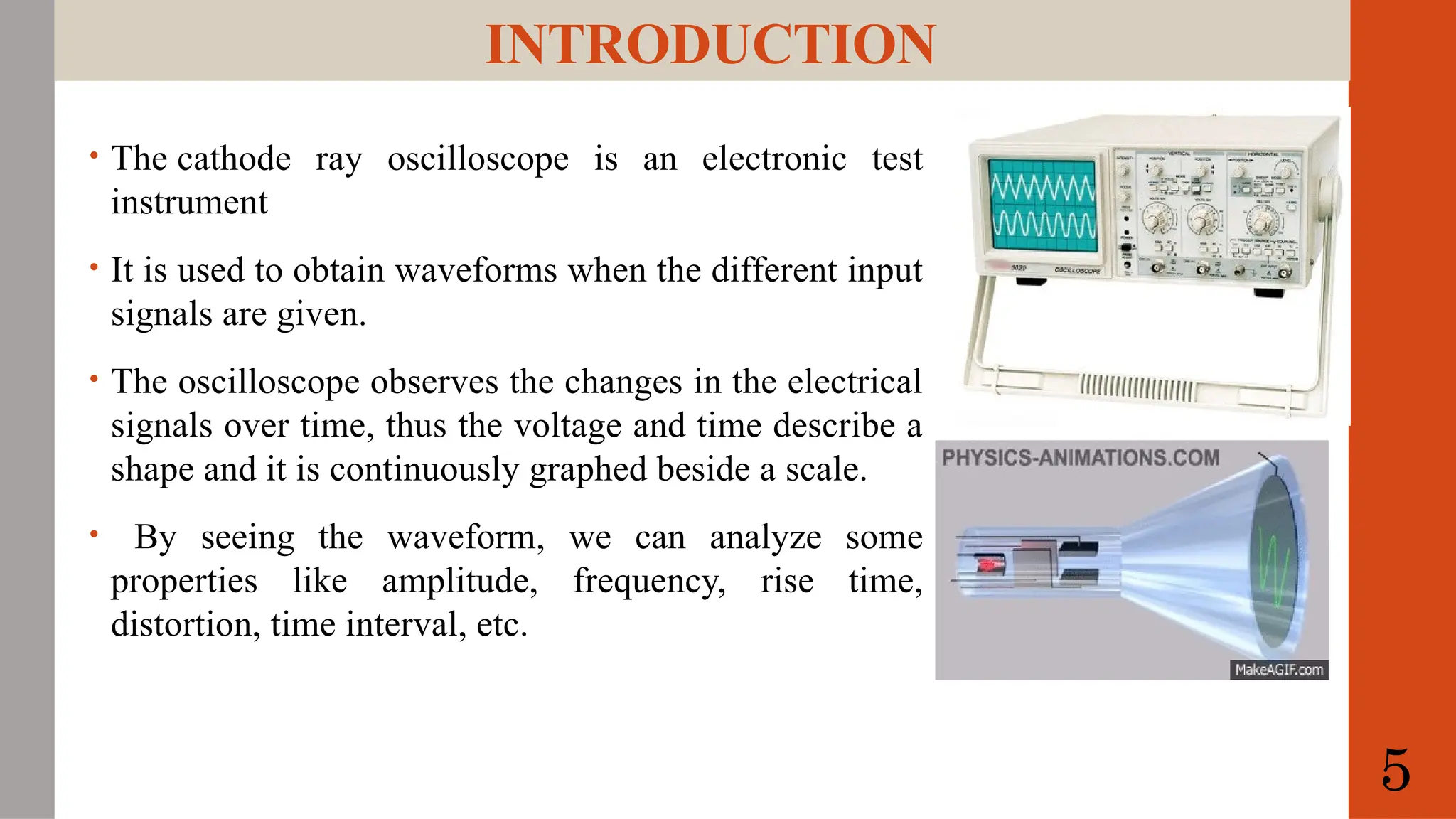
• The cathoderay oscilloscope is an electronic test
instrument
• It is used to obtain waveforms when the different input
signals are given.
• The oscilloscope observes the changes in the electrical
signals over time, thus the voltage and time describe a
shape and it is continuously graphed beside a scale.
• By seeing the waveform, we can analyze some
properties like amplitude, frequency, rise time,
distortion, time interval, etc.
5
Block Diagram ofCRO
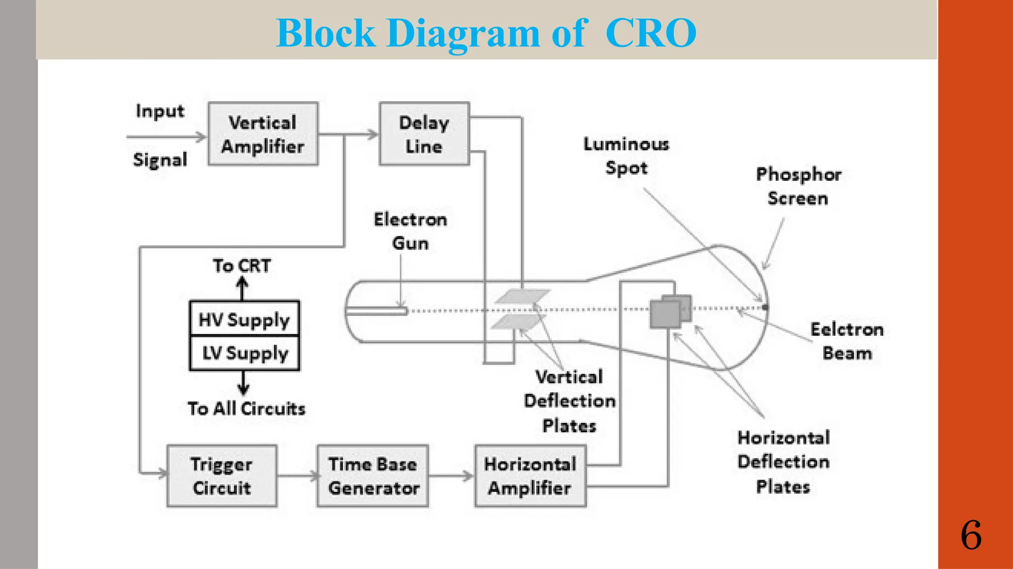
The Vertical Amplifier block amplifies the weak signals so that they produce
measurable deflection on the screen; this amplifier decides the sensitivity and
bandwidth of the CRO. Its output is given as input to the delay line.
The delay line: The delay line block adds a small delay to the signal before it
reaches the horizontal deflection plates. This helps avoid distortion on the screen
caused by the signal reaching the plates at different times.
Trigger Circuit: This circuit generates trigger pulses that keep the
synchronization between the input signal and the horizontal deflection circuit.
The time-based generator creates sawtooth waveforms for the horizontal
deflection plates, allowing calibration of the CRO in terms of time.
A horizontal amplifier boosts the sawtooth signal from a time-based generator
for the horizontal plates. 7
8.
Working principle
• ACRO (Cathode Ray Oscilloscope) works by using a high- speed electron beam
that is deflected by an electric or magnetic field to produce a visual display of an
electrical signal.
• When the electrical signal is applied to the two deflection plates to produce
electric fields perpendicular to each other.
• The electron beam is deflected by these fields, causing it to hit a phosphorescent
screen, producing a bright spot.
• The position of the spot on the screen represents the magnitude and waveform of
the electrical signal.
• By measuring the position of the spot, the frequency, amplitude, and waveform of
the signal can be determined.
7
9.
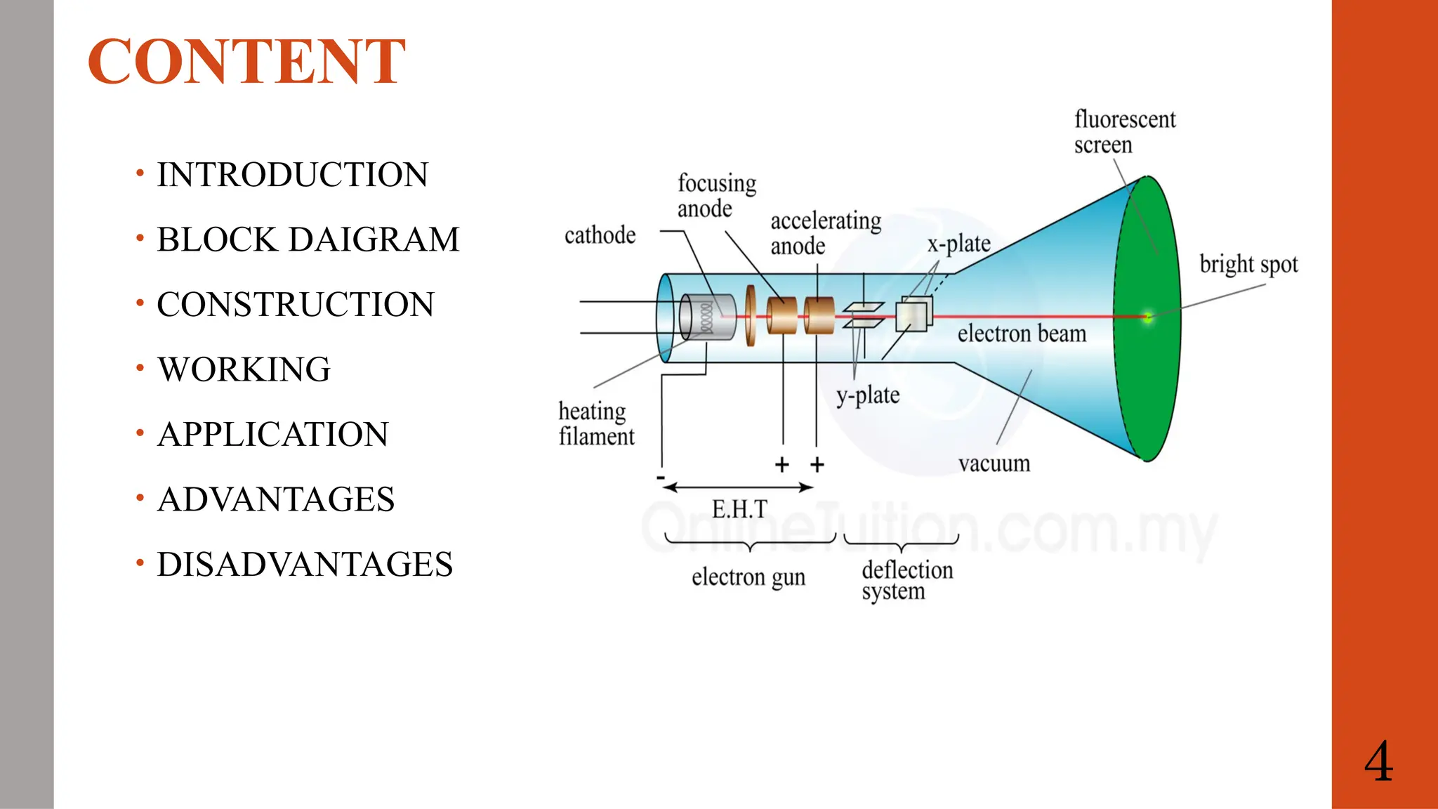
The construction ofCRO
Cathode Ray Tube
• Converts electrical signals into visual signals.
• Contains electrostatic deflection plates and an electron gun.
• Horizontal and vertical deflections are independent actions, moving the ray across
the monitor.
Electron Gun Assembly
• Emits electrons to form rays.
• Key components include a heater, grid, cathode, and anodes for acceleration and
focus.
• Strontium and barium layers at the cathode enhance electron emission at low
temperatures.
• Electrons flow through a co-axial along the CRT’s axis into a control grid.
9
10.
The construction ofCRO
Deflecting Plate
• Consists of vertical (Y plate) and horizontal (X plate) deflecting plates.
• Controls the electron ray direction after leaving the electron gun.
Fluorescent Screen
• Flat faceplate about 100 mm by 100 mm; larger screens are curved.
• Made by molding molten glass with an inner coating of phosphor crystals.
• Fluorescence occurs when electron rays strike phosphor crystals, producing light.
Glass Envelope
• Conical and evacuated structure.
• Inside faces are covered with aquadag, a conductive material.
• Assists the electrons by connecting to the accelerating anode.
10
11.
APPLICATIONS
It is usedin huge applications like radio stations for observing the transmitting &
receiving the properties of the signal.
It is used to measure the voltage, current, frequency, inductance, admittance,
resistance, and power factor.
This device is also used to check the AM and FM circuits characteristics
This device is used to monitor the signal properties as well as characteristics and
also controls the analog signals.
The shape of voltage and current waveform can be observed by CRO.
Used for comparing phase & frequency
To check the reactions of nervous and heartbeat.
11
12.
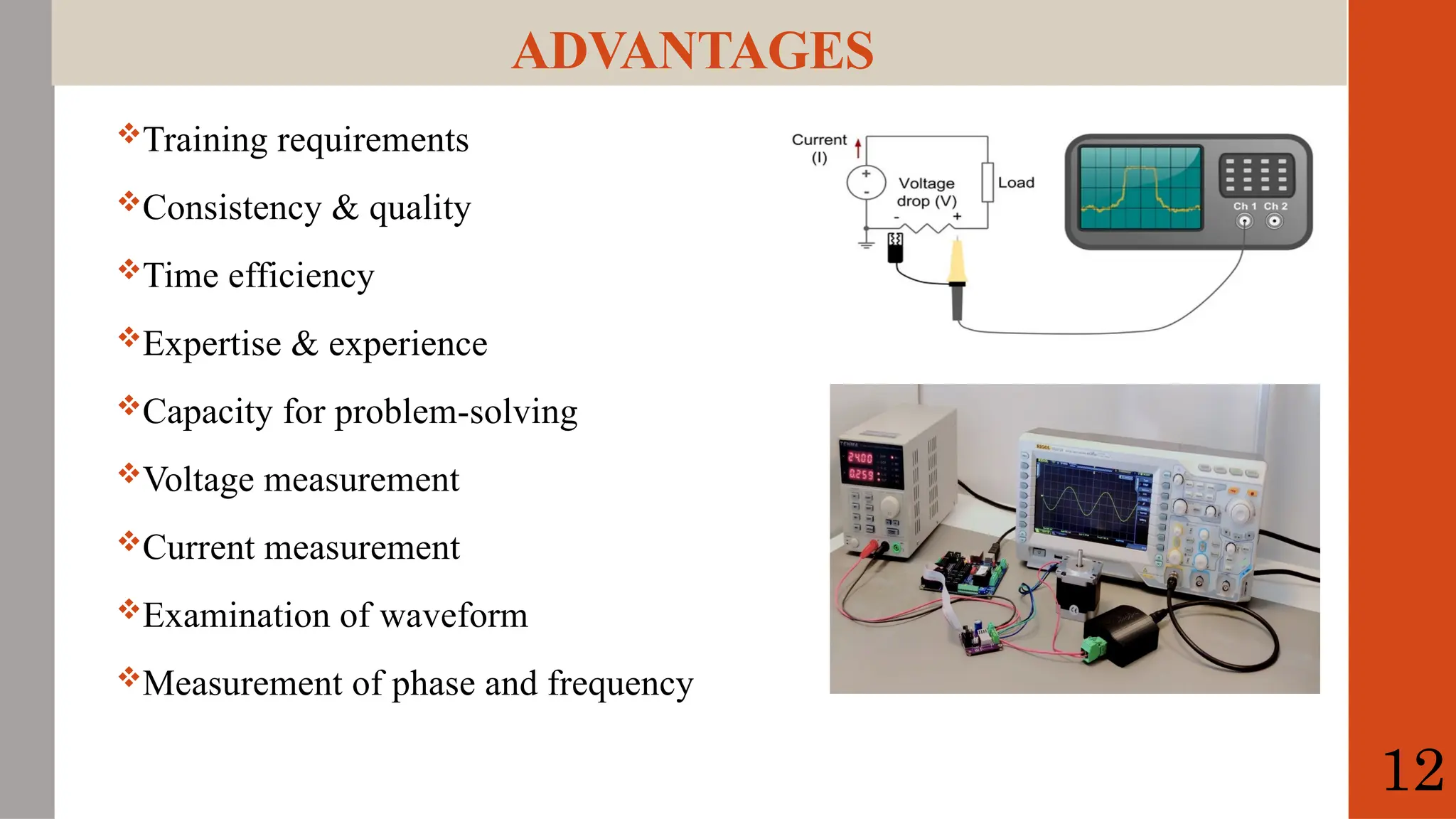
ADVANTAGES
Training requirements
Consistency &quality
Time efficiency
Expertise & experience
Capacity for problem-solving
Voltage measurement
Current measurement
Examination of waveform
Measurement of phase and frequency
12
13.
DISADVANTAGES
These oscilloscopes areexpensive as compared with other measuring devices
like multimeters.
They are complicated to repair once it gets damaged.
These devices need complete isolation
These are huge, heavy and uses more power
A lot of control terminals which is not so easy to understand at one instance But
for easy of use.
13
14.
Conclusion
In conclusion, thecathode ray oscilloscope (CRO) is a versatile and essential
tool for visualizing and analyzing electrical signals.
It utilizes a cathode ray tube (CRT) to display a visual representation of voltage
changes over time, making it indispensable in electronics and related fields.
Reference:
o https://www.elprocus.com
o https://www.geeksforgeeks.org
o http://testbook.com
14