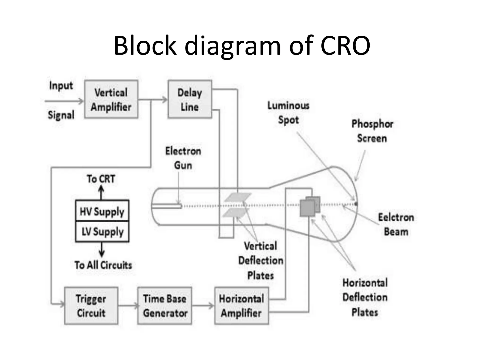
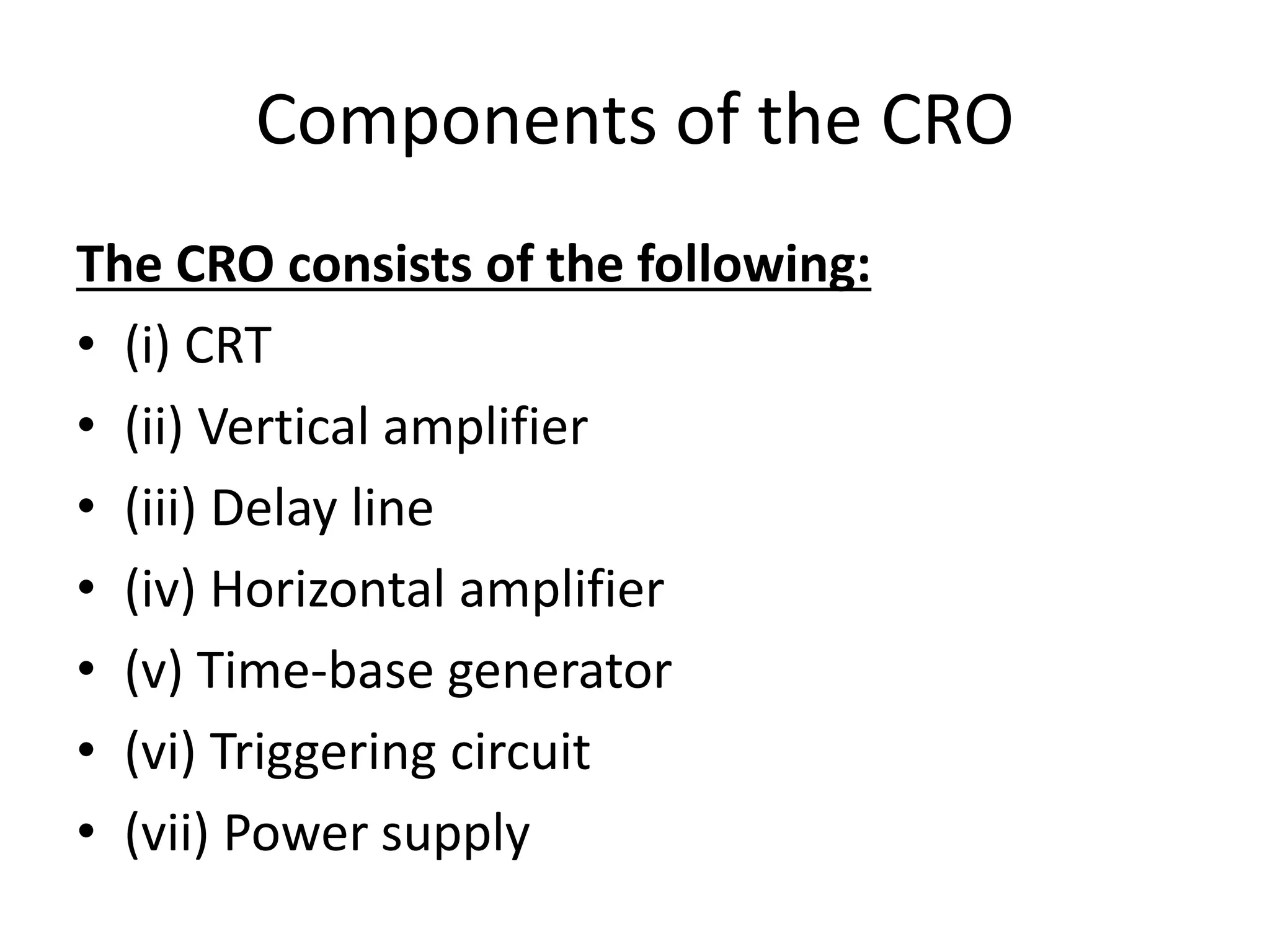
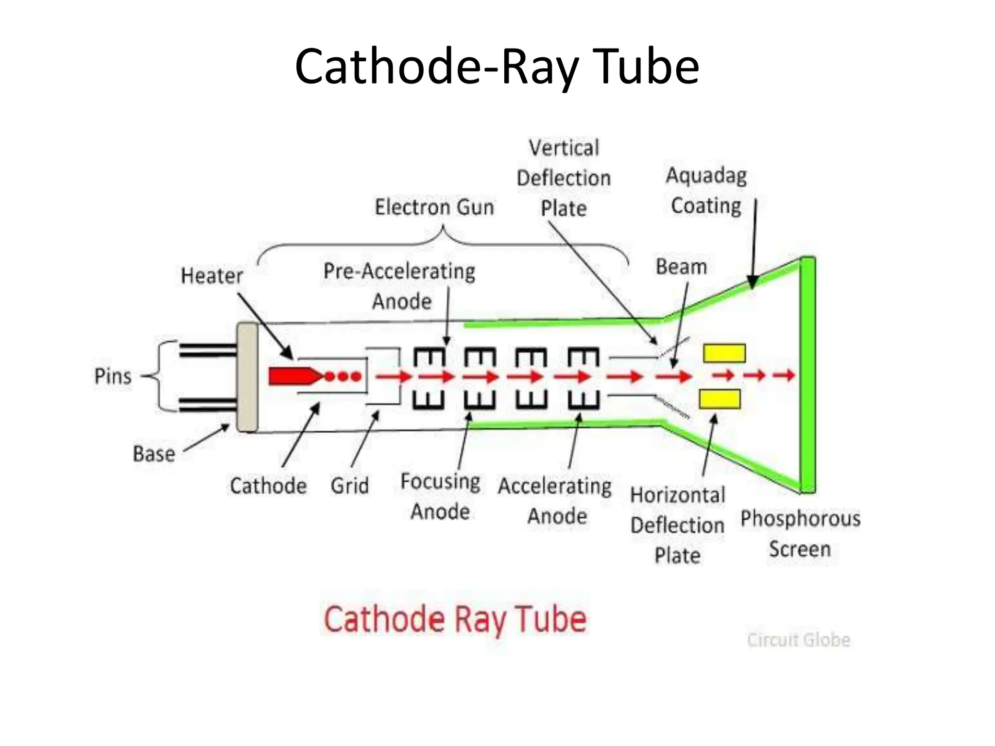
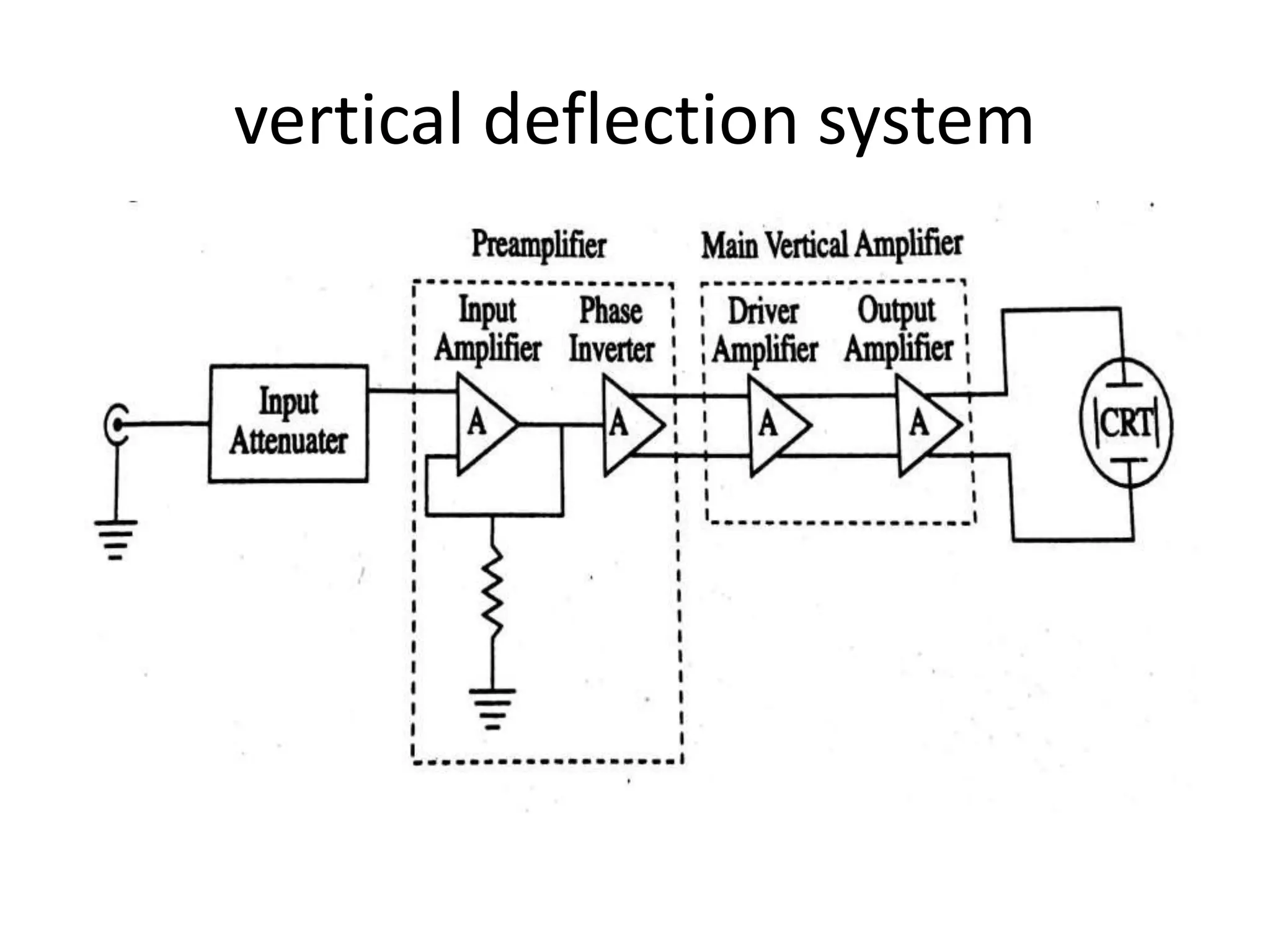
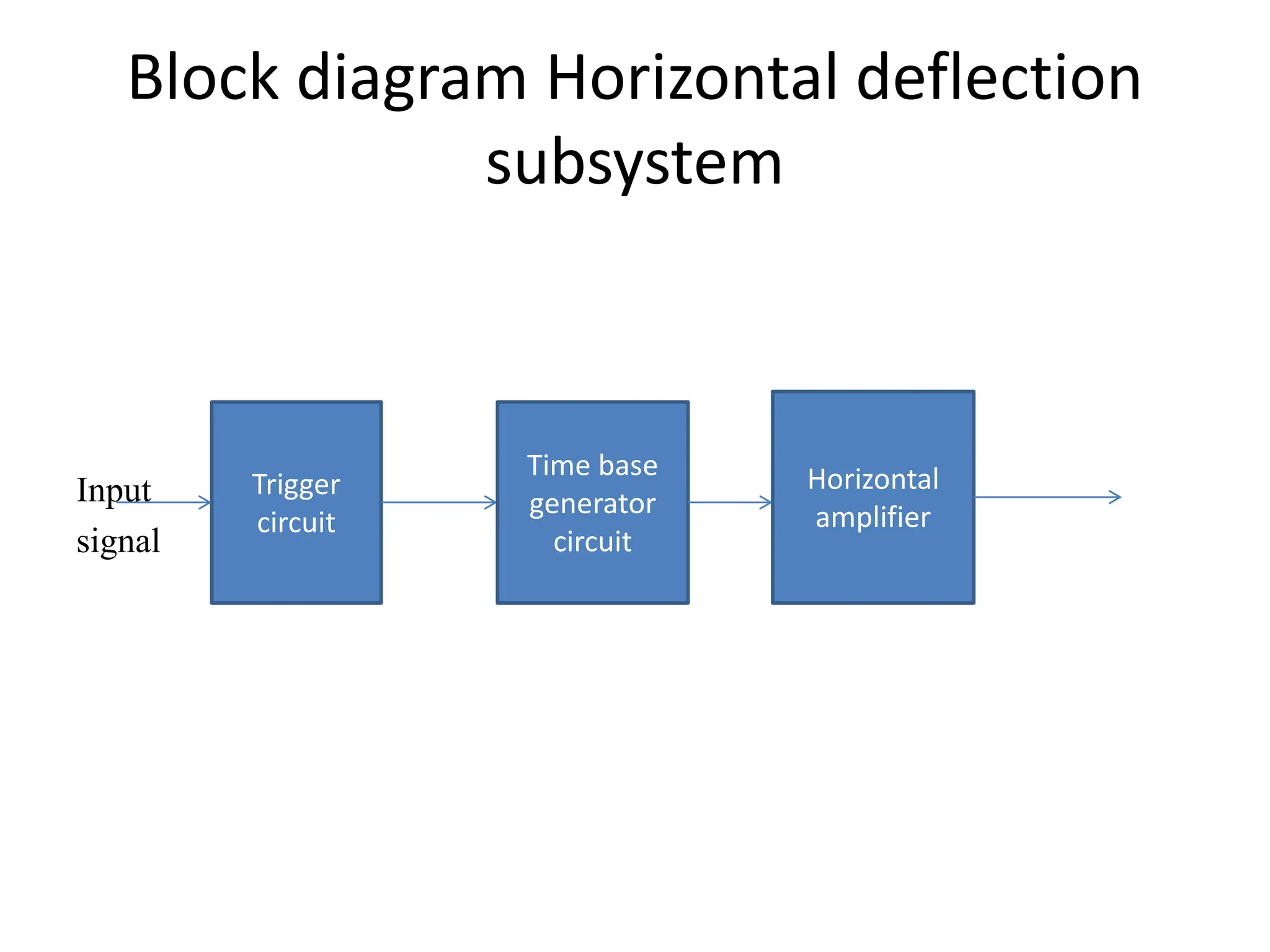
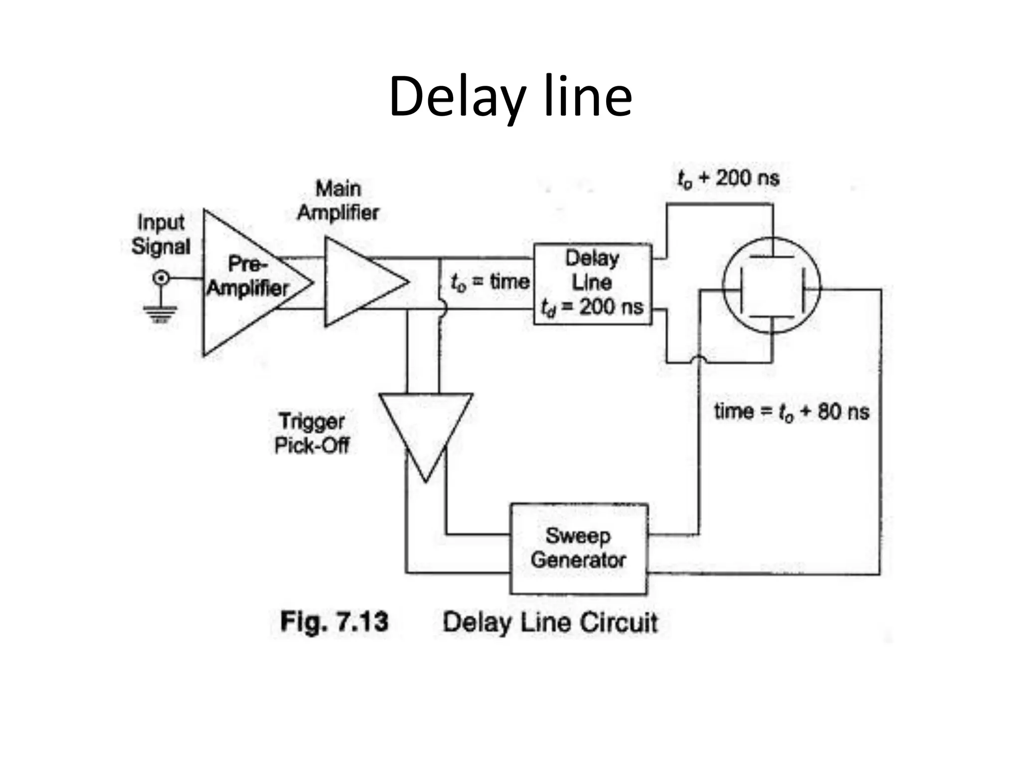
EMI
CHAPTER NO 3
Cathode ray oscilloscope
U.J.Maisale
Contents
Introduction
 Block diagram of the Cathode-Ray Oscilloscope
 Cathode-Ray Tube
• vertical deflection system
• Horizontal deflection system
• Delay Line
• Applications of CRO
INTRODUCTION:
 The cathode-ray oscilloscope (CRO) is a multipurpose
display instrument used for the observation,
measurement , and analysis of waveforms by plotting
amplitude along y-axis and time along x-axis.
 CRO is generally an x-y plotter; on a single screen it
can display different signals applied to different
channels. It can measure amplitude, frequencies and
phase shift of various signals.
 Many physical quantities like temperature, pressure
and strain can be converted into electrical signals by
the use of transducers, and the signals can be
displayed on the CRO.
 A moving luminous spot over the screen displays the
signal. CROs are used to study waveforms, and other
time-varying phenomena from very low to very high
frequencies.
 The central unit of the oscilloscope is the cathode-ray
tube (CRT), and the remaining part of the CRO
consists of the circuitry required to operate the
cathode-ray tube.
Block diagram of CRO
Components of the CRO
The CRO consists of the following:
• (i) CRT
• (ii) Vertical amplifier
• (iii) Delay line
• (iv) Horizontal amplifier
• (v) Time-base generator
• (vi) Triggering circuit
• (vii) Power supply
Cathode-Ray Tube
Cathode Ray Tube
• Electron Gun assembly
• Deflection Gun Assembly
• Fluorescent Gun Assembly
• Glass Envelope and Base of the tube
vertical deflection system
components
• Attenuator
• Vertical amplifier
Horizontal deflection system
• Time base generator
• Trigger circuit
• Horizontal amplifier
Block diagram Horizontal deflection
subsystem
Input
signal
Trigger
circuit
Time base
generator
circuit
Horizontal
amplifier
Delay line
Applications of CRO
• Voltage measurement
• Frequency measurement
• To see the waveforms
• Phase measurement
• Medical equipment
Thank you

Cathode Ray Oscilloscope

  • 1.
    EMI CHAPTER NO 3 Cathoderay oscilloscope U.J.Maisale
  • 2.
    Contents Introduction  Block diagramof the Cathode-Ray Oscilloscope  Cathode-Ray Tube • vertical deflection system • Horizontal deflection system • Delay Line • Applications of CRO
  • 3.
    INTRODUCTION:  The cathode-rayoscilloscope (CRO) is a multipurpose display instrument used for the observation, measurement , and analysis of waveforms by plotting amplitude along y-axis and time along x-axis.  CRO is generally an x-y plotter; on a single screen it can display different signals applied to different channels. It can measure amplitude, frequencies and phase shift of various signals.
  • 4.
     Many physicalquantities like temperature, pressure and strain can be converted into electrical signals by the use of transducers, and the signals can be displayed on the CRO.  A moving luminous spot over the screen displays the signal. CROs are used to study waveforms, and other time-varying phenomena from very low to very high frequencies.  The central unit of the oscilloscope is the cathode-ray tube (CRT), and the remaining part of the CRO consists of the circuitry required to operate the cathode-ray tube.
  • 5.
  • 6.
    Components of theCRO The CRO consists of the following: • (i) CRT • (ii) Vertical amplifier • (iii) Delay line • (iv) Horizontal amplifier • (v) Time-base generator • (vi) Triggering circuit • (vii) Power supply
  • 7.
  • 8.
    Cathode Ray Tube •Electron Gun assembly • Deflection Gun Assembly • Fluorescent Gun Assembly • Glass Envelope and Base of the tube
  • 9.
  • 10.
  • 11.
    Horizontal deflection system •Time base generator • Trigger circuit • Horizontal amplifier
  • 12.
    Block diagram Horizontaldeflection subsystem Input signal Trigger circuit Time base generator circuit Horizontal amplifier
  • 14.
  • 15.
    Applications of CRO •Voltage measurement • Frequency measurement • To see the waveforms • Phase measurement • Medical equipment
  • 16.