This document provides disassembly instructions for a torque converter in 3 steps:
1. Remove the torque converter housing from the transmission.
2. Disassemble the internal components of the torque converter housing.
3. Clean all torque converter parts thoroughly before inspection and assembly.
What Exactly Is The Common Rail Direct Injection System & How Does It WorkMotor Cars International
Learn about Common Rail Direct Injection (CRDi) - the revolutionary technology that has made diesel engines more efficient. Explore its workings, advantages like enhanced fuel efficiency and increased power output, along with drawbacks such as complexity and higher initial cost. Compare CRDi with traditional diesel engines and discover why it's the preferred choice for modern engines.
In this presentation, we have discussed a very important feature of BMW X5 cars… the Comfort Access. Things that can significantly limit its functionality. And things that you can try to restore the functionality of such a convenient feature of your vehicle.
5 Warning Signs Your BMW's Intelligent Battery Sensor Needs AttentionBertini's German Motors
IBS monitors and manages your BMW’s battery performance. If it malfunctions, you will have to deal with an array of electrical issues in your vehicle. Recognize warning signs like dimming headlights, frequent battery replacements, and electrical malfunctions to address potential IBS issues promptly.
What Does the Active Steering Malfunction Warning Mean for Your BMWTanner Motors
Discover the reasons why your BMW’s Active Steering malfunction warning might come on. From electrical glitches to mechanical failures and software anomalies, addressing these promptly with professional inspection and maintenance ensures continued safety and performance on the road, maintaining the integrity of your driving experience.
Symptoms like intermittent starting and key recognition errors signal potential problems with your Mercedes’ EIS. Use diagnostic steps like error code checks and spare key tests. Professional diagnosis and solutions like EIS replacement ensure safe driving. Consult a qualified technician for accurate diagnosis and repair.
"Trans Failsafe Prog" on your BMW X5 indicates potential transmission issues requiring immediate action. This safety feature activates in response to abnormalities like low fluid levels, leaks, faulty sensors, electrical or mechanical failures, and overheating.
What Does the PARKTRONIC Inoperative, See Owner's Manual Message Mean for You...Autohaus Service and Sales
Learn what "PARKTRONIC Inoperative, See Owner's Manual" means for your Mercedes-Benz. This message indicates a malfunction in the parking assistance system, potentially due to sensor issues or electrical faults. Prompt attention is crucial to ensure safety and functionality. Follow steps outlined for diagnosis and repair in the owner's manual.
Why Is Your BMW X3 Hood Not Responding To Release CommandsDart Auto
Experiencing difficulty opening your BMW X3's hood? This guide explores potential issues like mechanical obstruction, hood release mechanism failure, electrical problems, and emergency release malfunctions. Troubleshooting tips include basic checks, clearing obstructions, applying pressure, and using the emergency release.
Things to remember while upgrading the brakes of your carjennifermiller8137
Upgrading the brakes of your car? Keep these things in mind before doing so. Additionally, start using an OBD 2 GPS tracker so that you never miss a vehicle maintenance appointment. On top of this, a car GPS tracker will also let you master good driving habits that will let you increase the operational life of your car’s brakes.
𝘼𝙣𝙩𝙞𝙦𝙪𝙚 𝙋𝙡𝙖𝙨𝙩𝙞𝙘 𝙏𝙧𝙖𝙙𝙚𝙧𝙨 𝙞𝙨 𝙫𝙚𝙧𝙮 𝙛𝙖𝙢𝙤𝙪𝙨 𝙛𝙤𝙧 𝙢𝙖𝙣𝙪𝙛𝙖𝙘𝙩𝙪𝙧𝙞𝙣𝙜 𝙩𝙝𝙚𝙞𝙧 𝙥𝙧𝙤𝙙𝙪𝙘𝙩𝙨. 𝙒𝙚 𝙝𝙖𝙫𝙚 𝙖𝙡𝙡 𝙩𝙝𝙚 𝙥𝙡𝙖𝙨𝙩𝙞𝙘 𝙜𝙧𝙖𝙣𝙪𝙡𝙚𝙨 𝙪𝙨𝙚𝙙 𝙞𝙣 𝙖𝙪𝙩𝙤𝙢𝙤𝙩𝙞𝙫𝙚 𝙖𝙣𝙙 𝙖𝙪𝙩𝙤 𝙥𝙖𝙧𝙩𝙨 𝙖𝙣𝙙 𝙖𝙡𝙡 𝙩𝙝𝙚 𝙛𝙖𝙢𝙤𝙪𝙨 𝙘𝙤𝙢𝙥𝙖𝙣𝙞𝙚𝙨 𝙗𝙪𝙮 𝙩𝙝𝙚 𝙜𝙧𝙖𝙣𝙪𝙡𝙚𝙨 𝙛𝙧𝙤𝙢 𝙪𝙨.
Over the 10 years, we have gained a strong foothold in the market due to our range's high quality, competitive prices, and time-lined delivery schedules.
Core technology of Hyundai Motor Group's EV platform 'E-GMP'Hyundai Motor Group
What’s the force behind Hyundai Motor Group's EV performance and quality?
Maximized driving performance and quick charging time through high-density battery pack and fast charging technology and applicable to various vehicle types!
Discover more about Hyundai Motor Group’s EV platform ‘E-GMP’!
Comprehensive program for Agricultural Finance, the Automotive Sector, and Empowerment . We will define the full scope and provide a detailed two-week plan for identifying strategic partners in each area within Limpopo, including target areas.:
1. Agricultural : Supporting Primary and Secondary Agriculture
• Scope: Provide support solutions to enhance agricultural productivity and sustainability.
• Target Areas: Polokwane, Tzaneen, Thohoyandou, Makhado, and Giyani.
2. Automotive Sector: Partnerships with Mechanics and Panel Beater Shops
• Scope: Develop collaborations with automotive service providers to improve service quality and business operations.
• Target Areas: Polokwane, Lephalale, Mokopane, Phalaborwa, and Bela-Bela.
3. Empowerment : Focusing on Women Empowerment
• Scope: Provide business support support and training to women-owned businesses, promoting economic inclusion.
• Target Areas: Polokwane, Thohoyandou, Musina, Burgersfort, and Louis Trichardt.
We will also prioritize Industrial Economic Zone areas and their priorities.
Sign up on https://profilesmes.online/welcome/
To be eligible:
1. You must have a registered business and operate in Limpopo
2. Generate revenue
3. Sectors : Agriculture ( primary and secondary) and Automative
Women and Youth are encouraged to apply even if you don't fall in those sectors.
1. Shutdown SIS
Previous Screen
Product: WHEEL LOADER
Model: 980H WHEEL LOADER A8J
Configuration: 980H WHEEL LOADER A8J04000-UP (MACHINE) POWERED BY C15 ENGINE
Disassembly and Assembly
980H Wheel Loader Power Train
Media Number -RENR8667-08 Publication Date -01/09/2018 Date Updated -04/09/2018
i04400940
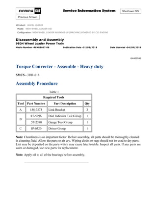
Torque Converter - Assemble - Heavy duty
SMCS - 3101-016
Assembly Procedure
Table 1
Required Tools
Tool Part Number Part Description Qty
A 138-7573 Link Bracket 3
B
8T-5096 Dial Indicator Test Group 1
5P-2390 Gauge Tool Group 1
C 1P-0520 Driver Group 1
Note: Cleanliness is an important factor. Before assembly, all parts should be thoroughly cleaned
in cleaning fluid. Allow the parts to air dry. Wiping cloths or rags should not be used to dry parts.
Lint may be deposited on the parts which may cause later trouble. Inspect all parts. If any parts are
worn or damaged, use new parts for replacement.
Note: Apply oil to all of the bearings before assembly.
1/18
980H WHEEL LOADER A8J04000-UP (MACHINE) POWERED BY C15 ENGINE(...
2021/3/27
https://127.0.0.1/sisweb/sisweb/techdoc/techdoc_print_page.jsp?returnurl=/sis...
2. Illustration 1 g00504278
1. Use Tooling (C) to install sleeve bearing (59) in cover assembly (57). Sleeve bearing (59)
must be even with the outside surface of cover assembly (57).
Illustration 2 g00504279
2. Install cover assembly (57) to rotating housing (39).
Illustration 3 g00503564
3. Install ring seal (58) to rotating housing (39).
2/18
980H WHEEL LOADER A8J04000-UP (MACHINE) POWERED BY C15 ENGINE(...
2021/3/27
https://127.0.0.1/sisweb/sisweb/techdoc/techdoc_print_page.jsp?returnurl=/sis...
3. 4. Install eight bolts (56) and the washers. Tighten the bolts to a torque of 30 ± 5 N·m
(22 ± 4 lb ft).
Illustration 4 g00504307
5. Install thrust bearing race (54), thrust bearing (55), and thrust bearing race (54) to cover
assembly (57).
Illustration 5 g00504312
6. Install retaining ring (53) in turbine hub (51).
Illustration 6 g00504313
3/18
980H WHEEL LOADER A8J04000-UP (MACHINE) POWERED BY C15 ENGINE(...
2021/3/27
https://127.0.0.1/sisweb/sisweb/techdoc/techdoc_print_page.jsp?returnurl=/sis...
4. 7. Install converter turbine (50) on turbine hub (51).
Illustration 7 g00504315
8. Install twenty bolts (52). Tighten the bolts to a torque of 50 ± 7 N·m (37 ± 5 lb ft).
Illustration 8 g00504382
9. Install turbine hub (51) and converter turbine (50) as a unit to rotating housing (39).
Illustration 9 g00503538
10. Install two thrust bearing races (49) and the bearing to the hub.
4/18
980H WHEEL LOADER A8J04000-UP (MACHINE) POWERED BY C15 ENGINE(...
2021/3/27
https://127.0.0.1/sisweb/sisweb/techdoc/techdoc_print_page.jsp?returnurl=/sis...
5. Illustration 10 g00504436
11. Use Tooling (C) to install sleeve bearing (48) to carrier assembly (44). Bearing sleeve (48)
must be even with the counterbore of carrier assembly (44).
Illustration 11 g00504882
12. Install retainer ring (47) in stator (46).
Illustration 12 g00504931
13. Position carrier assembly (44) on a wood block.
5/18
980H WHEEL LOADER A8J04000-UP (MACHINE) POWERED BY C15 ENGINE(...
2021/3/27
https://127.0.0.1/sisweb/sisweb/techdoc/techdoc_print_page.jsp?returnurl=/sis...
6. 14. Use proper equipment to handle stator (46). Heat stator (46) to a maximum temperature of
121°C (250°F) for one hour.
15. Install stator (46) on carrier assembly (44).
Illustration 13 g00504935
16. Install snap ring (45) in stator (46).
Illustration 14 g00505049
17. Install stator (46) and carrier assembly (44) in rotating housing (39).
Illustration 15 g00503352
6/18
980H WHEEL LOADER A8J04000-UP (MACHINE) POWERED BY C15 ENGINE(...
2021/3/27
https://127.0.0.1/sisweb/sisweb/techdoc/techdoc_print_page.jsp?returnurl=/sis...
7. 18. Install two thrust bearing races (43) and the thrust bearing to the carrier assembly.
Illustration 16 g00503351
19. Position impeller hub (42) on a wood block.
20. Install converter impeller (41) on impeller hub (42).
Illustration 17 g00503350
21. Install drive flange (38) on converter impeller (41).
Illustration 18 g00503348
7/18
980H WHEEL LOADER A8J04000-UP (MACHINE) POWERED BY C15 ENGINE(...
2021/3/27
https://127.0.0.1/sisweb/sisweb/techdoc/techdoc_print_page.jsp?returnurl=/sis...
8. 22. Install twelve bolts (40). Tighten the bolts to a torque of 80 ± 10 N·m (60 ± 7 lb ft).
Illustration 19 g00503345
23. Install drive flange (38) on rotating housing (39). The weight of drive flange (38) is 23 kg
(51 lb).
24. Install 36 bolts (37) and the washers. Tighten the bolts to a torque of 30 ± 5 N·m
(22 ± 4 lb ft).
Illustration 20 g00505183
25. Install retaining ring (36) in the groove of drive gear (35).
8/18
980H WHEEL LOADER A8J04000-UP (MACHINE) POWERED BY C15 ENGINE(...
2021/3/27
https://127.0.0.1/sisweb/sisweb/techdoc/techdoc_print_page.jsp?returnurl=/sis...
9. Illustration 21 g00505224
26. Use the proper equipment to handle outer bearing race (60). Lower the temperature of outer
bearing race (60).
27. Install outer bearing race (60) in drive gear (35). Make sure that outer bearing race (60)
makes contact with retaining ring (36).
Illustration 22 g00505319
28. Install drive gear (35) on drive flange (38).
Illustration 23 g00505349
29. Install twelve bolts (34) and the washers. Tighten the bolts to a torque of 50 ± 7 N·m
(37 ± 5 lb ft).
9/18
980H WHEEL LOADER A8J04000-UP (MACHINE) POWERED BY C15 ENGINE(...
2021/3/27
https://127.0.0.1/sisweb/sisweb/techdoc/techdoc_print_page.jsp?returnurl=/sis...
10. Illustration 24 g00505352
30. Use the proper equipment to handle inner bearing (33). Heat inner bearing (33) to a
maximum temperature of 135°C (275°F). Install inner bearing (33) on bearing carrier (28).
Illustration 25 g00505358
31. Install retaining ring (32) in the groove of bearing carrier (28).
Illustration 26 g00505359
32. Use the proper equipment to handle ring carrier (31). Heat ring carrier (31) to a maximum
temperature of 135°C (275°F). Install ring carrier (31) on bearing carrier (28).
10/18
980H WHEEL LOADER A8J04000-UP (MACHINE) POWERED BY C15 ENGIN...
2021/3/27
https://127.0.0.1/sisweb/sisweb/techdoc/techdoc_print_page.jsp?returnurl=/sis...
11. Illustration 27 g00505387
33. Install seal ring (30) on ring carrier (31).
34. Install O-ring seal (29) on bearing carrier (28).
Illustration 28 g00505395
35. Install bearing carrier (28) in drive flange (38).
Illustration 29 g00505423
36. Install retaining ring (27) in carrier assembly (44) in order to hold bearing carrier (28) in
place.
11/18
980H WHEEL LOADER A8J04000-UP (MACHINE) POWERED BY C15 ENGIN...
2021/3/27
https://127.0.0.1/sisweb/sisweb/techdoc/techdoc_print_page.jsp?returnurl=/sis...
12. Illustration 30 g00503312
37. Install two studs (26) in torque converter housing assembly (2). Tighten the studs to a torque
of 100 ± 15 N·m (74 ± 11 lb ft).
Illustration 31 g00505444
38. Install retaining ring (24) in the groove of idler gear (15).
Illustration 32 g00505465
39. Use the proper equipment to handle bearing cup (25). Lower the temperature of bearing cup
(25). Install bearing cup (25) in idler gear (15).
12/18
980H WHEEL LOADER A8J04000-UP (MACHINE) POWERED BY C15 ENGIN...
2021/3/27
https://127.0.0.1/sisweb/sisweb/techdoc/techdoc_print_page.jsp?returnurl=/sis...
13. Illustration 33 g00505470
40. Flip idler gear (15) to the opposite side. Install bearing cup spacer (23) in idler gear (15).
The notch in bearing cup spacer (23) must be aligned with retaining ring (24).
Illustration 34 g00505479
41. Use the proper equipment to handle bearing cup (22). Lower the temperature of bearing cup
(22). Install bearing cup (22) in idler gear (15).
Illustration 35 g00505480
42. Install bearing cone (21), bearing cone spacer (20) and bearing cone (19) in idler gear (15).
13/18
980H WHEEL LOADER A8J04000-UP (MACHINE) POWERED BY C15 ENGIN...
2021/3/27
https://127.0.0.1/sisweb/sisweb/techdoc/techdoc_print_page.jsp?returnurl=/sis...
14. Illustration 36 g00505482
43. Apply clean hydraulic oil on O-ring seal (17). Install O-ring seal (17) on shaft assembly
(18).
Illustration 37 g00505508
44. Install 1/2" - 13 NC guide pin (61) in shaft assembly (18).
45. Hold transfer gear (15) in position in torque converter housing assembly (2). Install shaft
assembly (18).
46. Remove guide pin (61) from shaft assembly (18).
Illustration 38 g00505517
14/18
980H WHEEL LOADER A8J04000-UP (MACHINE) POWERED BY C15 ENGIN...
2021/3/27
https://127.0.0.1/sisweb/sisweb/techdoc/techdoc_print_page.jsp?returnurl=/sis...
15. 47. Install bolt (14) that holds shaft assembly (18) in place in torque converter housing
assembly (2). Tighten the bolt to a torque of 120 ± 20 N·m (90 ± 15 lb ft).
Illustration 39 g00505572
48. Use the proper equipment to handle bearing cones (12). Heat bearing cones to a maximum
temperature of 135°C (275°F). Install a bearing cone (12) on each side of pump drive gear
(11).
Illustration 40 g00505585
49. Use the proper equipment to handle bearing cup (13). Lower the temperature of bearing cup
(13). Install bearing cup (13) in torque converter housing assembly (2).
15/18
980H WHEEL LOADER A8J04000-UP (MACHINE) POWERED BY C15 ENGIN...
2021/3/27
https://127.0.0.1/sisweb/sisweb/techdoc/techdoc_print_page.jsp?returnurl=/sis...
16. Illustration 41 g00505591
50. Install pump drive gear (11) in torque converter housing assembly (2).
Illustration 42 g00505594
51. Use the proper equipment to handle bearing cup (8). Lower the temperature of bearing cup
(8). Install bearing cup (8) in pump adapter (6).
Illustration 43 g00505623
52. Install shims (9) on pump adapter (6).
53. Apply clean hydraulic oil on O-ring seal (10). Install O-ring seal (10) on pump adapter (6).
16/18
980H WHEEL LOADER A8J04000-UP (MACHINE) POWERED BY C15 ENGIN...
2021/3/27
https://127.0.0.1/sisweb/sisweb/techdoc/techdoc_print_page.jsp?returnurl=/sis...
17. Illustration 44 g00505666
54. Install two 3/8" - 16 NC guide pins (62) in torque converter housing assembly (2).
55. Install pump adapter (6) on torque converter housing assembly (2).
Illustration 45 g00505669
56. Install thirteen bolts (5) and the washers.
57. Use Tooling (B) to check bearing end play. The bearing end play must be 0.15 ± 0.05 mm
(.006 ± .002 inch). Add or remove shims in order to get the correct bearing end play.
Note: If end play is less than 0.10 mm (.004 inch) add additional shims. If end play is
greater than 0.20 mm (.008 inch) remove shims.
Illustration 46 g00505670
58. Apply clean hydraulic oil on O-ring seal (4). Install O-ring seal (4) on torque converter
housing assembly (2).
17/18
980H WHEEL LOADER A8J04000-UP (MACHINE) POWERED BY C15 ENGIN...
2021/3/27
https://127.0.0.1/sisweb/sisweb/techdoc/techdoc_print_page.jsp?returnurl=/sis...
18. Illustration 47 g01022823
59. Install two 1/2" - 13 NC guide pins (63) in the carrier assembly.
60. Install Tooling (A) to torque converter housing assembly (2), as shown. Attach a hoist and
suitable lifting chains to Tooling (A). Use the hoist to carefully install torque converter
housing assembly (2) on the torque converter.
Illustration 48 g00503225
61. Install eight bolts (1) and the washers to torque converter housing assembly (2). Tighten the
bolts to a torque of 120 ± 20 N·m (90 ± 15 lb ft).
End By:
a. Connect the torque converter to the transmission and to the output transfer gears. Refer to
Disassembly and Assembly, "Torque Converter to Transmission, Output Transfer Gears -
Connect" for the machine that is being serviced.
Copyright 1993 - 2021 Caterpillar Inc.
All Rights Reserved.
Private Network For SIS Licensees.
Sat Mar 27 14:45:45 UTC+0800 2021
18/18
980H WHEEL LOADER A8J04000-UP (MACHINE) POWERED BY C15 ENGIN...
2021/3/27
https://127.0.0.1/sisweb/sisweb/techdoc/techdoc_print_page.jsp?returnurl=/sis...
19. Shutdown SIS
Previous Screen
Product: WHEEL LOADER
Model: 980H WHEEL LOADER A8J
Configuration: 980H WHEEL LOADER A8J04000-UP (MACHINE) POWERED BY C15 ENGINE
Disassembly and Assembly
980H Wheel Loader Power Train
Media Number -RENR8667-08 Publication Date -01/09/2018 Date Updated -04/09/2018
i05903287
Torque Converter (Freewheel Stator) - Disassemble
SMCS - 3101-015
Disassembly Procedure
Table 1
Required Tools
Tool Part Number Part Description Qty
A 138-7573 Link Bracket 3
B
8B-7548 Push-Puller 1
8B-7550 Leg 2
8H-0684 Ratchet Wrench 1
8B-7560 Step Plate 1
8H-0663 Bearing Puller Attachment 1
C
8B-7548 Push-Puller 1
8H-0684 Ratchet Wrench 1
8B-7549 Leg 2
5P-4808 Cap 2
8B-7554 Bearing Cup Puller Attachment 1
D
5F-7343 Bearing Puller Attachment 1
1P-0520 Driver Group 1
E 1P-0510 Driver Group 1
F 7
1/19
980H WHEEL LOADER A8J04000-UP (MACHINE) POWERED BY C15 ENGINE(...
2021/3/27
https://127.0.0.1/sisweb/sisweb/techdoc/techdoc_print_page.jsp?returnurl=/sis...
20. Forcing Screw
3/8 - 16 x 3 in
Start By:
A. Separate the torque converter from the transmission and from the output transfer gears.
Refer to Disassembly and Assembly, "Torque Converter from Transmission, Output
Transfer Gears - Separate" for the machine that is being serviced.
1. Place the torque converter housing assembly (2) on wood blocks.
Illustration 1 g00503225
2. Remove bolts (1) and the washers from torque converter housing assembly (2) .
Illustration 2 g01111329
3. Install Tooling (A) to torque converter housing assembly (2) , as shown. Attach a suitable
lifting device to Tooling (A) . The weight of housing assembly (2) is approximately 120 kg
(265 lb).
4. Use Tooling (F) to loosen housing assembly (2) from the torque converter.
2/19
980H WHEEL LOADER A8J04000-UP (MACHINE) POWERED BY C15 ENGINE(...
2021/3/27
https://127.0.0.1/sisweb/sisweb/techdoc/techdoc_print_page.jsp?returnurl=/sis...
21. 5. Remove housing assembly (2) from the torque converter.
Illustration 3 g00871317
6. Remove O-ring seal (3) from torque converter housing assembly (2) .
Illustration 4 g00871318
7. Remove bolts (4) and the washers from pump adapter (5) and torque converter housing
assembly (2) .
3/19
980H WHEEL LOADER A8J04000-UP (MACHINE) POWERED BY C15 ENGINE(...
2021/3/27
https://127.0.0.1/sisweb/sisweb/techdoc/techdoc_print_page.jsp?returnurl=/sis...
22. Illustration 5 g00871264
8. Use Tooling (F) to remove pump adapter (5) from torque converter housing assembly (2) .
Illustration 6 g00871319
9. Use tooling (C) to remove bearing cup (6) , O-ring seal (8) , and shims (7) from pump
adapter (5) . See illustration 13 for Tooling (C) .
Illustration 7 g00871326
4/19
980H WHEEL LOADER A8J04000-UP (MACHINE) POWERED BY C15 ENGINE(...
2021/3/27
https://127.0.0.1/sisweb/sisweb/techdoc/techdoc_print_page.jsp?returnurl=/sis...
23. 10. Remove pump drive gear (9) from torque converter housing assembly (2) .
Illustration 8 g00871451
11. Use Tooling (B) to remove bearing cones (10) from each side to pump drive gear (9) .
Illustration 9 g00871333
12. Use Tooling (C) to remove bearing cup (11) from torque converter housing assembly (2) .
See illustration 13 for Tooling (C) .
5/19
980H WHEEL LOADER A8J04000-UP (MACHINE) POWERED BY C15 ENGINE(...
2021/3/27
https://127.0.0.1/sisweb/sisweb/techdoc/techdoc_print_page.jsp?returnurl=/sis...
24. Illustration 10 g01112900
13. Remove bolt (12) and the washer from torque converter housing assembly (2) .
14. Use Tooling (F) to push shaft assembly (14) out of torque converter housing assembly (2) .
15. Remove idler gear (13) from torque converter housing assembly (2) .
Illustration 11 g01112903
16. Remove O-ring seal (15) from shaft assembly (14) .
6/19
980H WHEEL LOADER A8J04000-UP (MACHINE) POWERED BY C15 ENGINE(...
2021/3/27
https://127.0.0.1/sisweb/sisweb/techdoc/techdoc_print_page.jsp?returnurl=/sis...
25. Illustration 12 g00871365
17. Remove bearing cone (16) , bearing cone spacer (17) , and bearing cone (18) from idler gear
(13) .
Illustration 13 g00871366
18. Use Tooling (C) to remove bearing cup (19) from idler gear (13) .
Illustration 14 g00871367
19. Remove bearing cup spacer (20) from idler gear (13) .
7/19
980H WHEEL LOADER A8J04000-UP (MACHINE) POWERED BY C15 ENGINE(...
2021/3/27
https://127.0.0.1/sisweb/sisweb/techdoc/techdoc_print_page.jsp?returnurl=/sis...
26. Illustration 15 g00871368
20. Remove retaining ring (21) from idler gear (13) .
Illustration 16 g00871369
21. Use Tooling (C) to remove bearing cups (22) from idler gear (13) .
8/19
980H WHEEL LOADER A8J04000-UP (MACHINE) POWERED BY C15 ENGINE(...
2021/3/27
https://127.0.0.1/sisweb/sisweb/techdoc/techdoc_print_page.jsp?returnurl=/sis...
27. Illustration 17 g00871370
22. Remove studs (23) from torque converter housing assembly (2) .
Illustration 18 g00871267
23. Remove retaining ring (24) and bearing carrier (25) from the carrier assembly.
Illustration 19 g01112906
24. Remove bearing carrier (25) .
9/19
980H WHEEL LOADER A8J04000-UP (MACHINE) POWERED BY C15 ENGINE(...
2021/3/27
https://127.0.0.1/sisweb/sisweb/techdoc/techdoc_print_page.jsp?returnurl=/sis...
28. Illustration 20 g00871269
25. Remove O-ring seal (26) from bearing carrier (25) .
26. Remove seal ring (27) from ring carrier (28) .
Illustration 21 g00871273
27. Use Tooling (D) and a press to remove ring carrier (28) from bearing carrier (25) .
10/19
980H WHEEL LOADER A8J04000-UP (MACHINE) POWERED BY C15 ENGIN...
2021/3/27
https://127.0.0.1/sisweb/sisweb/techdoc/techdoc_print_page.jsp?returnurl=/sis...
29. Illustration 22 g00871274
28. Remove retaining ring (29) from bearing carrier (25) .
Illustration 23 g00871275
29. Use Tooling (D) and a press to remove inner bearing (30) from bearing carrier (25) .
Illustration 24 g01112907
30. Remove bolts (31) and the washers from drive gear (32) .
31. Remove drive gear (32) .
11/19
980H WHEEL LOADER A8J04000-UP (MACHINE) POWERED BY C15 ENGIN...
2021/3/27
https://127.0.0.1/sisweb/sisweb/techdoc/techdoc_print_page.jsp?returnurl=/sis...
30. Illustration 25 g01112910
32. Use Tooling (E) and a press to remove the outer bearing race (32A) (not shown) from drive
gear (32) .
Illustration 26 g00871278
33. Remove retaining ring (33) from drive gear (32) .
Illustration 27 g00871279
12/19
980H WHEEL LOADER A8J04000-UP (MACHINE) POWERED BY C15 ENGIN...
2021/3/27
https://127.0.0.1/sisweb/sisweb/techdoc/techdoc_print_page.jsp?returnurl=/sis...
31. 34. Remove bolts (34) and the washers from drive flange (35) and rotating housing (36) .
Illustration 28 g00871281
35. Use bolts (34) as forcing screws to remove drive flange (35) from rotating housing (36) .
The weight of drive flange (35) is 23 kg (51 lb).
Illustration 29 g00871282
36. Remove bolts (37) from drive flange (35) .
13/19
980H WHEEL LOADER A8J04000-UP (MACHINE) POWERED BY C15 ENGIN...
2021/3/27
https://127.0.0.1/sisweb/sisweb/techdoc/techdoc_print_page.jsp?returnurl=/sis...
32. Illustration 30 g00871283
37. Remove drive flange (35) from impeller (38) .
Illustration 31 g00871284
38. Position impeller hub (39) on wood blocks.
39. Remove impeller (38) from impeller hub (39) .
Illustration 32 g00870210
14/19
980H WHEEL LOADER A8J04000-UP (MACHINE) POWERED BY C15 ENGIN...
2021/3/27
https://127.0.0.1/sisweb/sisweb/techdoc/techdoc_print_page.jsp?returnurl=/sis...
33. Suggest:
If the above button click is invalid.
Please download this document
first, and then click the above link
to download the complete manual.
Thank you so much for reading
34. 40. Remove thrust bearing (40) and race (40A) (not shown) from carrier assembly (41) .
Illustration 33 g00870211
41. Remove carrier assembly (41) and stator (42) as a unit from rotating housing (36) .
Illustration 34 g00870212
42. Remove snap ring (43) from stator (42) . Remove plate (44) from stator (42) .
15/19
980H WHEEL LOADER A8J04000-UP (MACHINE) POWERED BY C15 ENGIN...
2021/3/27
https://127.0.0.1/sisweb/sisweb/techdoc/techdoc_print_page.jsp?returnurl=/sis...
35. Illustration 35 g01112913
43. Remove 11 freewheel rollers (45) and 11 freewheel springs (46) from freewheel cam (47) .
Remove stator (42) from carrier assembly (41) .
Illustration 36 g01112915
44. Remove retaining ring (48) . Remove plate (49) .
45. Use Tooling (E) and a hydraulic press in order to remove freewheel cam (47) from stator
(42) .
Note: If necessary, heat the stator to a maximum temperature of 135 °C (275 °F) for
approximately 15 minutes.
Illustration 37 g01112917
46. Remove thrust bearing (50) from carrier assembly (41) . Remove sleeve bearing (51) from
carrier assembly (41) .
16/19
980H WHEEL LOADER A8J04000-UP (MACHINE) POWERED BY C15 ENGIN...
2021/3/27
https://127.0.0.1/sisweb/sisweb/techdoc/techdoc_print_page.jsp?returnurl=/sis...