SlideShare a Scribd company logo
Product: WHEEL LOADER
Model: 928F WHEEL LOADER 2XL
Configuration: 928F WHEEL LOADER 2XL01300-UP (MACHINE) POWERED BY 3116 ENGINE
Disassembly and Assembly
928F WHEEL LOADER POWER TRAIN
Media Number -SENR5995-02 Publication Date -01/10/2003 Date Updated -26/10/2004
SENR59950012
Differential (NoSPIN)
SMCS - 3265-015; 3265-016
Disassemble Differential (NoSPIN)
Start By:
a. Remove differentials and pinion assemblies.
Typical Example
1. Put alignment marks on the differential case halves.
There is spring force against the differential case half. When bolts (2)
are removed, the spring force will be released. To prevent possible
personal injury, removal of the case half should be performed in a press
in order to retain the case half.
2. Put the differential in a press, and remove bolts (2). Slowly release the spring compression.
1/4(W)
w
2022/8/1
https://127.0.0.1/sisweb/sisweb/techdoc/techdoc_print_page.jsp?returnurl=/sisweb/siswe...
3. Remove the differential case half.
4. Remove side gear (8), spacer block (9), retainer (10), spring (11) and hold out ring and clutch
assembly (12).
5. Remove spider cam assembly (6), hold out ring and clutch assembly (7), spring (13), retainer
(4), and side gear (5).
Assemble Differential (NoSPIN)
2/4(W)
w
2022/8/1
https://127.0.0.1/sisweb/sisweb/techdoc/techdoc_print_page.jsp?returnurl=/sisweb/siswe...
Personal injury can result from being struck by parts propelled by a
released spring force. Make sure to wear all necessary protective
equipment.
Follow the recommended procedure and use all recommended tooling to
release the spring force.
1. Put one of the case halves in a press.
2. Install side gear (5), retainer (4), spring (13), holdout ring and clutch assembly (7) and spider
cam assembly (6).
3/4(W)
w
2022/8/1
https://127.0.0.1/sisweb/sisweb/techdoc/techdoc_print_page.jsp?returnurl=/sisweb/siswe...
3. Install holdout ring and clutch assembly (12), spring (11), retainer (10), spacer block (9) and
side gear (8).
Typical Example
4. Install case half (3). Use press to compress the springs in the differential.
Typical Example
NOTICE
A new differential group or a new case assembly will be equipped with
four bolts and washers that are used for shipping, assembly and
storage purposes only. Remove and discard these four bolts and
washers after the bevel gear has been installed. These four bolts and
washers should not be used for final assembly.
5. Install bolts (2) that hold the differential case halves together.
End By:
a. install the differential and pinion assemblies
4/4(W)
w
2022/8/1
https://127.0.0.1/sisweb/sisweb/techdoc/techdoc_print_page.jsp?returnurl=/sisweb/siswe...
Product: WHEEL LOADER
Model: 928F WHEEL LOADER 2XL
Configuration: 928F WHEEL LOADER 2XL01300-UP (MACHINE) POWERED BY 3116 ENGINE
Disassembly and Assembly
928F WHEEL LOADER POWER TRAIN
Media Number -SENR5995-02 Publication Date -01/10/2003 Date Updated -26/10/2004
SENR59950013
Engine & Transmission
SMCS - 1012-029; 1013-010; 3001-029; 3153-016; 3153-015
Remove & Install Engine & Transmission
Start By:
a. Remove radiator and guard.
b. Remove hydraulic tank**.
c. Remove cab**.
d. Remove steering cylinders**.
e. Remove drive shaft group*.
*Refer to the Power Train Disassembly & Assembly module for this information.
NOTE: Identify and mark all lines, hoses and electrical wiring before removing or disconnecting
for purposes of reassembly.
1/14(W)
w
2022/8/1
https://127.0.0.1/sisweb/sisweb/techdoc/techdoc_print_page.jsp?returnurl=/sisweb/siswe...
1. Remove condenser line (2).
2. Disconnect plug connect (1).
3. Disconnect wire (3) on the solenoid.
4. Disconnect two quick connects (4).
5. Remove two fuel lines (5).
6. Remove two bolts, washers and clips (6) and reposition cable (7).
7. Loosen two clamps (8) and remove the heater lines.
8. Disconnect two spade connectors (9).
9. Remove two bolts and washers (10) and bracket (11).
2/14(W)
w
2022/8/1
https://127.0.0.1/sisweb/sisweb/techdoc/techdoc_print_page.jsp?returnurl=/sisweb/siswe...
10. Disconnect quick connect (12) and remove air dryer (13).
11. Disconnect two ground wires (14).
12. Disconnect quick connect (15).
13. Disconnect all wires (16) from the alternator.
14. Disconnect all wires (17) from the starter and solenoid.
15. Disconnect plug connector (18) and spade connector (19).
16. Remove hydraulic line (20).
17. Disconnect quick connect (21).
18. Reposition wiring harness (22).
3/14(W)
w
2022/8/1
https://127.0.0.1/sisweb/sisweb/techdoc/techdoc_print_page.jsp?returnurl=/sisweb/siswe...
19. Disconnect quick connect (23).
20. Disconnect six plugs (24) and reposition wire harness (25).
21. Disconnect quick connect (26) on lower right side of transmission.
22. Remove two bolts, washers and clips (27) holding parking brake (28) to the frame assembly.
23. Remove hydraulic line (29).
4/14(W)
w
2022/8/1
https://127.0.0.1/sisweb/sisweb/techdoc/techdoc_print_page.jsp?returnurl=/sisweb/siswe...
24. Attach tool (A) to engine and transmission and a suitable lifting device.
25. Remove two mounting bolts and washers (30) holding the engine to the frame.
26. Remove eight bolts and washers (31) from brackets (32).
27. Remove two mounting bolts and washers (33) from two brackets (32).
28. Remove the engine and transmission as shown. The weight of the engine and transmission is
1362 kg (3000 lb).
NOTE: Install in the reverse order.
End By:
a. install drive shaft*
b. install steering valve and diverter valve*
c. install steering cylinders**
d. install radiator and guard
e. install hydraulic tank**
f. install cab**
5/14(W)
w
2022/8/1
https://127.0.0.1/sisweb/sisweb/techdoc/techdoc_print_page.jsp?returnurl=/sisweb/siswe...
*Refer to the Power Train Disassembly & Assembly module for this information.
**Refer to the Machine Systems Disassembly & Assembly module for this information.
Separate & Connect Engine From Transmission
Start By:
a. remove engine & transmission
1. Support transmission and engine using tooling (A) and wood blocks as shown.
2. Disconnect all wire clips and connectors.
3. Attach suitable lifting device to the transmission, remove bolts and washers (1) and separate
transmission from engine.
NOTE: Connect engine & transmisison in the reverse order.
End By:
a. install engine & transmission
Separation & Connection of Torque Converter From
Transmission
6/14(W)
w
2022/8/1
https://127.0.0.1/sisweb/sisweb/techdoc/techdoc_print_page.jsp?returnurl=/sisweb/siswe...
Start By:
a. remove transmission
1. Thoroughly clean the outside of the transmission prior to disassembly.
2. Drain the transmission fluid into a suitable container.
3. Mark all parts and components for assembly purposes.
4. Install tool (A), chains and a suitable lifting device to transmission (1) as shown. The weight of
the transmission is 700 kg (1545 lb).
5. Move the transmission to a clean safe work area and install on Tool (B) as shown.
6. Install tooling (C), chains and a suitable lifting device to transmission cover (2) as shown.
NOTE: Use a bubble level to get the cover as level as possible.
7/14(W)
w
2022/8/1
https://127.0.0.1/sisweb/sisweb/techdoc/techdoc_print_page.jsp?returnurl=/sisweb/siswe...
7. Remove twenty seven bolts (3).
8. Slowly and carefully lift the transmission cover straight up far enough to clear input shaft (4).
The weight of the transmission cover is 200 kg (440 lb).
NOTE: Install in the reverse order.
NOTE: Use 6V6640 Gasket Maker on mating surfaces of the torque converter and the
transmission.
9. Tighten twenty seven bolts (3) to the torque of 55 ± 10 N·m (40 ± 7 lb ft).
Disassemble Transmission Pump
1. Remove two bolts (1) and cover (2).
2. Remove seven bolts (3). Check O-ring seal (4) for damage or wear and replace if necessary.
8/14(W)
w
2022/8/1
https://127.0.0.1/sisweb/sisweb/techdoc/techdoc_print_page.jsp?returnurl=/sisweb/siswe...
3. Install two forcing screws as shown.
4. Use tool (A), chains and a suitable lifting device to remove gear pump group (5).
5. Remove six bolts (6).
6. Remove shaft (7).
7. Use tool (B) to remove retaining ring (8).
9/14(W)
w
2022/8/1
https://127.0.0.1/sisweb/sisweb/techdoc/techdoc_print_page.jsp?returnurl=/sisweb/siswe...
8. Remove gear (9) and ball bearing (10) as a unit.
9. Use a suitable press to remove ball bearing (10) from gear (9).
10. Remove five bolts (11).
NOTE: Only one of these bolts marked (X) has a washer.
11. Turn gear pump group (5) over and remove one bolt (12).
12. Separate pump cover assembly (13) from gear pump group (5).
13. If necessary, remove two bushings (14).
14. Check O-ring seal (15) for damage or wear and replace if necessary.
10/14(W)
w
2022/8/1
https://127.0.0.1/sisweb/sisweb/techdoc/techdoc_print_page.jsp?returnurl=/sisweb/siswe...
15. Remove two oil pump gears (16). Mark these gears and their location for assembly purposes.
16. Check the condition of the two dowels (17) and replace if necessary.
17. Check the condition of the two dowels (18) and replace if necessary.
18. If necessary, remove two bushings (19).
Assemble Transmission Pump
1. If removed, install two bushings (19).
11/14(W)
w
2022/8/1
https://127.0.0.1/sisweb/sisweb/techdoc/techdoc_print_page.jsp?returnurl=/sisweb/siswe...
2. Install two oil pump gears (16).
3. Check the condition of two dowels (17) and replace if necessary.
4. Check the condition of two dowels (18) and replace if necessary.
5. If removed, install two bushings (14).
6. Check O-ring seal (15) for damage or wear and replace if necessary.
7. Turn gear pump group (5) over and install one bolt (12).
8. Connect pump cover assembly (13) to gear pump group (5).
9. Install five bolts (11).
NOTE: Only one of these bolts marked (X) has a washer.
12/14(W)
w
2022/8/1
https://127.0.0.1/sisweb/sisweb/techdoc/techdoc_print_page.jsp?returnurl=/sisweb/siswe...
10. Heat bearing (10) to 135°C (275°F) and install in gear (9).
11. Install gear (9) and bearing (10) as a unit.
12. Use tool (B) to install retaining ring (186).
13. Install shaft (7).
13/14(W)
w
2022/8/1
https://127.0.0.1/sisweb/sisweb/techdoc/techdoc_print_page.jsp?returnurl=/sisweb/siswe...
14. Install six bolts (6).
15. Use tool (A), chains and a suitable lifting device to install gear pump group (5).
16. Install seven bolts (3). Check O-ring seal (4) for damage or wear and replace if necessary.
17. Install two bolts (1) and cover (2).
14/14(W)
w
2022/8/1
https://127.0.0.1/sisweb/sisweb/techdoc/techdoc_print_page.jsp?returnurl=/sisweb/siswe...
Product: WHEEL LOADER
Model: 928F WHEEL LOADER 2XL
Configuration: 928F WHEEL LOADER 2XL01300-UP (MACHINE) POWERED BY 3116 ENGINE
Disassembly and Assembly
928F WHEEL LOADER POWER TRAIN
Media Number -SENR5995-02 Publication Date -01/10/2003 Date Updated -26/10/2004
SENR59950014
Torque Converter
SMCS - 3101-015; 3101-016
Disassemble Torque Converter
Start By:
a. remove engine, transmission and torque converter
b. separation of engine from transmission and torque converter
c. separation of transmission from torque converter
1. Install tool (A) as shown.
2. Remove six bolts (1).
3. Lift transmission cover (2) straight up and off the torque converter. The weight of the
transmission cover if 150 kg (330 lb).
1/9(W)
w
2022/8/1
https://127.0.0.1/sisweb/sisweb/techdoc/techdoc_print_page.jsp?returnurl=/sisweb/siswe...
4. Install tool (A) as shown.
5. Remove eighteen bolts (2) and washers.
6. Install two forcing screws as shown.
7. Separate drive gear (3) and stator carrier (4) from rotating housing (5).
8. Remove six socket head bolts (6).
9. Remove two clamp plates (7).
10. Use tool (B) to remove retaining ring (8).
2/9(W)
w
2022/8/1
https://127.0.0.1/sisweb/sisweb/techdoc/techdoc_print_page.jsp?returnurl=/sisweb/siswe...
11. Carefully tap stator carrier (4) from converter impeller (9).
12. Check seal ring (11) for damage or wear and replace if necessary.
13. Remove twelve bolts (12).
14. Remove drive gear (3) from converter impeller (9).
15. Use a suitable press to remove ball bearing (13) from converter impeller (9).
16. Use tool (B) to remove retaining ring (14).
3/9(W)
w
2022/8/1
https://127.0.0.1/sisweb/sisweb/techdoc/techdoc_print_page.jsp?returnurl=/sisweb/siswe...
17. Lift converter turbine (15) from rotating housing (5).
18. Remove rear bearing lock (16).
19. Remove end cover (17).
20. Turn the rotating housing over and use a soft hammer to tap splined hub and ball bearing (18)
out of the housing.
4/9(W)
w
2022/8/1
https://127.0.0.1/sisweb/sisweb/techdoc/techdoc_print_page.jsp?returnurl=/sisweb/siswe...
21. Use tool (B) to remove snap ring (19) from splined hub (18).
22. If necessary, remove ball bearing (20) from splined hub (18).
23. Check the condition of locating ring (21) on the outside diameter of ball bearing (20) and
replace if necessary.
24. Check oil damn or "D" ring (22) for damage or wear and replace if necessary.
Assemble Torque Converter
1. Check oil damn or "D" ring (22) for damage or wear and replace if necessary.
2. Use tool (B) to install snap ring (19) to splined hub (18).
3. If removed, install bearing (20) to splined hub (18).
4. Check the condition of locating ring (21) on the outside diameter of bearing (20) and replace if
necessary.
5/9(W)
w
2022/8/1
https://127.0.0.1/sisweb/sisweb/techdoc/techdoc_print_page.jsp?returnurl=/sisweb/siswe...
5. Turn the rotating housing over and assemble splined hub and bearing (18) to the housing.
6. Install end cover (17).
7. Install rear bearing lock (16).
8. Assemble converter turbine (15) to rotating housing (5).
9. Use tool (B) to install retaining ring (14).
6/9(W)
w
2022/8/1
https://127.0.0.1/sisweb/sisweb/techdoc/techdoc_print_page.jsp?returnurl=/sisweb/siswe...
Suggest:
For more complete manuals. Please go to
the home page.
https://www.ebooklibonline.com
If the above button click is invalid. Please
download this document first, and then
click the above link to download the
complete manual.
Thank you so much for reading
10. Heat bearing (13) to 135°C (275°F) and assemble to impeller (9).
11. Install drive gear (3) to impeller (9).
12. Install twelve bolts (12) and tighten to the torque of 30 ± 5 N·m (22 ± 4 lb ft).
13. Check seal ring (11) for damage or wear and replace if necessary.
14. If removed, install six spring pins (10).
15. Carefully install stator carrier (4) to impeller (9).
7/9(W)
w
2022/8/1
https://127.0.0.1/sisweb/sisweb/techdoc/techdoc_print_page.jsp?returnurl=/sisweb/siswe...
16. Install two clamp plates (7).
17. Use tool (B) to install retaining ring (8).
18. Install six socket head bolts (6) and tighten to the torque of 30 ± 5 N·m (22 ± 4 lb ft).
19. Assemble drive gear (3) and stator carrier (4) to rotating housing (5).
20. Install tool (A) as shown.
21. Install eighteen bolts (2) and the washers and tighten to a torque of 30 ± 5 N·m (22 ± 4 lb ft).
8/9(W)
w
2022/8/1
https://127.0.0.1/sisweb/sisweb/techdoc/techdoc_print_page.jsp?returnurl=/sisweb/siswe...

More Related Content

More from ti76cui

Caterpillar Cat D5N TRACK-TYPE TRACTOR (Prefix AKD) Service Repair Manual Ins...
Caterpillar Cat D5N TRACK-TYPE TRACTOR (Prefix AKD) Service Repair Manual Ins...Caterpillar Cat D5N TRACK-TYPE TRACTOR (Prefix AKD) Service Repair Manual Ins...
Caterpillar Cat D5N TRACK-TYPE TRACTOR (Prefix AKD) Service Repair Manual Ins...
ti76cui
 
Caterpillar Cat D5K XL TRACK-TYPE TRACTOR (Prefix WWW) Service Repair Manual ...
Caterpillar Cat D5K XL TRACK-TYPE TRACTOR (Prefix WWW) Service Repair Manual ...Caterpillar Cat D5K XL TRACK-TYPE TRACTOR (Prefix WWW) Service Repair Manual ...
Caterpillar Cat D5K XL TRACK-TYPE TRACTOR (Prefix WWW) Service Repair Manual ...
ti76cui
 
Caterpillar Cat D4K2 XL TRACK-TYPE TRACTOR (Prefix MT3) Service Repair Manual...
Caterpillar Cat D4K2 XL TRACK-TYPE TRACTOR (Prefix MT3) Service Repair Manual...Caterpillar Cat D4K2 XL TRACK-TYPE TRACTOR (Prefix MT3) Service Repair Manual...
Caterpillar Cat D4K2 XL TRACK-TYPE TRACTOR (Prefix MT3) Service Repair Manual...
ti76cui
 
Caterpillar Cat D4K2 XL TRACK-TYPE TRACTOR (Prefix KM2) Service Repair Manual...
Caterpillar Cat D4K2 XL TRACK-TYPE TRACTOR (Prefix KM2) Service Repair Manual...Caterpillar Cat D4K2 XL TRACK-TYPE TRACTOR (Prefix KM2) Service Repair Manual...
Caterpillar Cat D4K2 XL TRACK-TYPE TRACTOR (Prefix KM2) Service Repair Manual...
ti76cui
 
Caterpillar Cat CB564D Vibratory Compactor (Prefix D4M) Service Repair Manual...
Caterpillar Cat CB564D Vibratory Compactor (Prefix D4M) Service Repair Manual...Caterpillar Cat CB564D Vibratory Compactor (Prefix D4M) Service Repair Manual...
Caterpillar Cat CB564D Vibratory Compactor (Prefix D4M) Service Repair Manual...
ti76cui
 
Caterpillar Cat C15 Industrial Engine (Prefix N5F) Service Repair Manual Inst...
Caterpillar Cat C15 Industrial Engine (Prefix N5F) Service Repair Manual Inst...Caterpillar Cat C15 Industrial Engine (Prefix N5F) Service Repair Manual Inst...
Caterpillar Cat C15 Industrial Engine (Prefix N5F) Service Repair Manual Inst...
ti76cui
 
Caterpillar Cat C13 Industrial Engine (Prefix N3F) Service Repair Manual Inst...
Caterpillar Cat C13 Industrial Engine (Prefix N3F) Service Repair Manual Inst...Caterpillar Cat C13 Industrial Engine (Prefix N3F) Service Repair Manual Inst...
Caterpillar Cat C13 Industrial Engine (Prefix N3F) Service Repair Manual Inst...
ti76cui
 
Caterpillar Cat C13 Industrial Engine (Prefix LGK) Service Repair Manual Inst...
Caterpillar Cat C13 Industrial Engine (Prefix LGK) Service Repair Manual Inst...Caterpillar Cat C13 Industrial Engine (Prefix LGK) Service Repair Manual Inst...
Caterpillar Cat C13 Industrial Engine (Prefix LGK) Service Repair Manual Inst...
ti76cui
 
Caterpillar Cat C2.2 Industrial Engine (Prefix J26) Service Repair Manual Ins...
Caterpillar Cat C2.2 Industrial Engine (Prefix J26) Service Repair Manual Ins...Caterpillar Cat C2.2 Industrial Engine (Prefix J26) Service Repair Manual Ins...
Caterpillar Cat C2.2 Industrial Engine (Prefix J26) Service Repair Manual Ins...
ti76cui
 
Caterpillar Cat 3512E Marine Engine (Prefix SY3) Service Repair Manual Instan...
Caterpillar Cat 3512E Marine Engine (Prefix SY3) Service Repair Manual Instan...Caterpillar Cat 3512E Marine Engine (Prefix SY3) Service Repair Manual Instan...
Caterpillar Cat 3512E Marine Engine (Prefix SY3) Service Repair Manual Instan...
ti76cui
 
Caterpillar Cat 3512B Industrial Engine (Prefix BR2) Service Repair Manual In...
Caterpillar Cat 3512B Industrial Engine (Prefix BR2) Service Repair Manual In...Caterpillar Cat 3512B Industrial Engine (Prefix BR2) Service Repair Manual In...
Caterpillar Cat 3512B Industrial Engine (Prefix BR2) Service Repair Manual In...
ti76cui
 
Caterpillar Cat 3512 Industrial Engine (Prefix SR2) Service Repair Manual Ins...
Caterpillar Cat 3512 Industrial Engine (Prefix SR2) Service Repair Manual Ins...Caterpillar Cat 3512 Industrial Engine (Prefix SR2) Service Repair Manual Ins...
Caterpillar Cat 3512 Industrial Engine (Prefix SR2) Service Repair Manual Ins...
ti76cui
 
Caterpillar Cat 988F Series II Wheel Loader (Prefix 2ZR) Service Repair Manua...
Caterpillar Cat 988F Series II Wheel Loader (Prefix 2ZR) Service Repair Manua...Caterpillar Cat 988F Series II Wheel Loader (Prefix 2ZR) Service Repair Manua...
Caterpillar Cat 988F Series II Wheel Loader (Prefix 2ZR) Service Repair Manua...
ti76cui
 
Caterpillar Cat 988B Wheel Loader (Prefix 50W) Service Repair Manual Instant ...
Caterpillar Cat 988B Wheel Loader (Prefix 50W) Service Repair Manual Instant ...Caterpillar Cat 988B Wheel Loader (Prefix 50W) Service Repair Manual Instant ...
Caterpillar Cat 988B Wheel Loader (Prefix 50W) Service Repair Manual Instant ...
ti76cui
 
Caterpillar Cat 988 988K XE Wheel Loader (Prefix E8X) Service Repair Manual I...
Caterpillar Cat 988 988K XE Wheel Loader (Prefix E8X) Service Repair Manual I...Caterpillar Cat 988 988K XE Wheel Loader (Prefix E8X) Service Repair Manual I...
Caterpillar Cat 988 988K XE Wheel Loader (Prefix E8X) Service Repair Manual I...
ti76cui
 
Caterpillar Cat 977K TRACK LOADER (Prefix 48J) Service Repair Manual Instant ...
Caterpillar Cat 977K TRACK LOADER (Prefix 48J) Service Repair Manual Instant ...Caterpillar Cat 977K TRACK LOADER (Prefix 48J) Service Repair Manual Instant ...
Caterpillar Cat 977K TRACK LOADER (Prefix 48J) Service Repair Manual Instant ...
ti76cui
 
Caterpillar Cat 977K 977L TRACK LOADER (Prefix 48J) Service Repair Manual Ins...
Caterpillar Cat 977K 977L TRACK LOADER (Prefix 48J) Service Repair Manual Ins...Caterpillar Cat 977K 977L TRACK LOADER (Prefix 48J) Service Repair Manual Ins...
Caterpillar Cat 977K 977L TRACK LOADER (Prefix 48J) Service Repair Manual Ins...
ti76cui
 
Caterpillar Cat 977K 977L TRACK LOADER (Prefix 11K) Service Repair Manual Ins...
Caterpillar Cat 977K 977L TRACK LOADER (Prefix 11K) Service Repair Manual Ins...Caterpillar Cat 977K 977L TRACK LOADER (Prefix 11K) Service Repair Manual Ins...
Caterpillar Cat 977K 977L TRACK LOADER (Prefix 11K) Service Repair Manual Ins...
ti76cui
 

More from ti76cui (20)

Caterpillar Cat D5N TRACK-TYPE TRACTOR (Prefix AKD) Service Repair Manual Ins...
Caterpillar Cat D5N TRACK-TYPE TRACTOR (Prefix AKD) Service Repair Manual Ins...Caterpillar Cat D5N TRACK-TYPE TRACTOR (Prefix AKD) Service Repair Manual Ins...
Caterpillar Cat D5N TRACK-TYPE TRACTOR (Prefix AKD) Service Repair Manual Ins...
 
Caterpillar Cat D5K XL TRACK-TYPE TRACTOR (Prefix WWW) Service Repair Manual ...
Caterpillar Cat D5K XL TRACK-TYPE TRACTOR (Prefix WWW) Service Repair Manual ...Caterpillar Cat D5K XL TRACK-TYPE TRACTOR (Prefix WWW) Service Repair Manual ...
Caterpillar Cat D5K XL TRACK-TYPE TRACTOR (Prefix WWW) Service Repair Manual ...
 
Caterpillar Cat D4K2 XL TRACK-TYPE TRACTOR (Prefix MT3) Service Repair Manual...
Caterpillar Cat D4K2 XL TRACK-TYPE TRACTOR (Prefix MT3) Service Repair Manual...Caterpillar Cat D4K2 XL TRACK-TYPE TRACTOR (Prefix MT3) Service Repair Manual...
Caterpillar Cat D4K2 XL TRACK-TYPE TRACTOR (Prefix MT3) Service Repair Manual...
 
Caterpillar Cat D4K2 XL TRACK-TYPE TRACTOR (Prefix KM2) Service Repair Manual...
Caterpillar Cat D4K2 XL TRACK-TYPE TRACTOR (Prefix KM2) Service Repair Manual...Caterpillar Cat D4K2 XL TRACK-TYPE TRACTOR (Prefix KM2) Service Repair Manual...
Caterpillar Cat D4K2 XL TRACK-TYPE TRACTOR (Prefix KM2) Service Repair Manual...
 
Caterpillar Cat CB564D Vibratory Compactor (Prefix D4M) Service Repair Manual...
Caterpillar Cat CB564D Vibratory Compactor (Prefix D4M) Service Repair Manual...Caterpillar Cat CB564D Vibratory Compactor (Prefix D4M) Service Repair Manual...
Caterpillar Cat CB564D Vibratory Compactor (Prefix D4M) Service Repair Manual...
 
Caterpillar Cat C15 Industrial Engine (Prefix N5F) Service Repair Manual Inst...
Caterpillar Cat C15 Industrial Engine (Prefix N5F) Service Repair Manual Inst...Caterpillar Cat C15 Industrial Engine (Prefix N5F) Service Repair Manual Inst...
Caterpillar Cat C15 Industrial Engine (Prefix N5F) Service Repair Manual Inst...
 
Caterpillar Cat C13 Industrial Engine (Prefix N3F) Service Repair Manual Inst...
Caterpillar Cat C13 Industrial Engine (Prefix N3F) Service Repair Manual Inst...Caterpillar Cat C13 Industrial Engine (Prefix N3F) Service Repair Manual Inst...
Caterpillar Cat C13 Industrial Engine (Prefix N3F) Service Repair Manual Inst...
 
Caterpillar Cat C13 Industrial Engine (Prefix LGK) Service Repair Manual Inst...
Caterpillar Cat C13 Industrial Engine (Prefix LGK) Service Repair Manual Inst...Caterpillar Cat C13 Industrial Engine (Prefix LGK) Service Repair Manual Inst...
Caterpillar Cat C13 Industrial Engine (Prefix LGK) Service Repair Manual Inst...
 
Caterpillar Cat C2.2 Industrial Engine (Prefix J26) Service Repair Manual Ins...
Caterpillar Cat C2.2 Industrial Engine (Prefix J26) Service Repair Manual Ins...Caterpillar Cat C2.2 Industrial Engine (Prefix J26) Service Repair Manual Ins...
Caterpillar Cat C2.2 Industrial Engine (Prefix J26) Service Repair Manual Ins...
 
Caterpillar Cat 3512E Marine Engine (Prefix SY3) Service Repair Manual Instan...
Caterpillar Cat 3512E Marine Engine (Prefix SY3) Service Repair Manual Instan...Caterpillar Cat 3512E Marine Engine (Prefix SY3) Service Repair Manual Instan...
Caterpillar Cat 3512E Marine Engine (Prefix SY3) Service Repair Manual Instan...
 
Caterpillar Cat 3512B Industrial Engine (Prefix BR2) Service Repair Manual In...
Caterpillar Cat 3512B Industrial Engine (Prefix BR2) Service Repair Manual In...Caterpillar Cat 3512B Industrial Engine (Prefix BR2) Service Repair Manual In...
Caterpillar Cat 3512B Industrial Engine (Prefix BR2) Service Repair Manual In...
 
Caterpillar Cat 3512 Industrial Engine (Prefix SR2) Service Repair Manual Ins...
Caterpillar Cat 3512 Industrial Engine (Prefix SR2) Service Repair Manual Ins...Caterpillar Cat 3512 Industrial Engine (Prefix SR2) Service Repair Manual Ins...
Caterpillar Cat 3512 Industrial Engine (Prefix SR2) Service Repair Manual Ins...
 
Caterpillar Cat 988F Series II Wheel Loader (Prefix 2ZR) Service Repair Manua...
Caterpillar Cat 988F Series II Wheel Loader (Prefix 2ZR) Service Repair Manua...Caterpillar Cat 988F Series II Wheel Loader (Prefix 2ZR) Service Repair Manua...
Caterpillar Cat 988F Series II Wheel Loader (Prefix 2ZR) Service Repair Manua...
 
Caterpillar Cat 988B Wheel Loader (Prefix 50W) Service Repair Manual Instant ...
Caterpillar Cat 988B Wheel Loader (Prefix 50W) Service Repair Manual Instant ...Caterpillar Cat 988B Wheel Loader (Prefix 50W) Service Repair Manual Instant ...
Caterpillar Cat 988B Wheel Loader (Prefix 50W) Service Repair Manual Instant ...
 
Caterpillar Cat 988 988K XE Wheel Loader (Prefix E8X) Service Repair Manual I...
Caterpillar Cat 988 988K XE Wheel Loader (Prefix E8X) Service Repair Manual I...Caterpillar Cat 988 988K XE Wheel Loader (Prefix E8X) Service Repair Manual I...
Caterpillar Cat 988 988K XE Wheel Loader (Prefix E8X) Service Repair Manual I...
 
Caterpillar Cat 977K TRACK LOADER (Prefix 48J) Service Repair Manual Instant ...
Caterpillar Cat 977K TRACK LOADER (Prefix 48J) Service Repair Manual Instant ...Caterpillar Cat 977K TRACK LOADER (Prefix 48J) Service Repair Manual Instant ...
Caterpillar Cat 977K TRACK LOADER (Prefix 48J) Service Repair Manual Instant ...
 
Caterpillar Cat 977K 977L TRACK LOADER (Prefix 48J) Service Repair Manual Ins...
Caterpillar Cat 977K 977L TRACK LOADER (Prefix 48J) Service Repair Manual Ins...Caterpillar Cat 977K 977L TRACK LOADER (Prefix 48J) Service Repair Manual Ins...
Caterpillar Cat 977K 977L TRACK LOADER (Prefix 48J) Service Repair Manual Ins...
 
Caterpillar Cat 977K 977L TRACK LOADER (Prefix 48J) Service Repair Manual Ins...
Caterpillar Cat 977K 977L TRACK LOADER (Prefix 48J) Service Repair Manual Ins...Caterpillar Cat 977K 977L TRACK LOADER (Prefix 48J) Service Repair Manual Ins...
Caterpillar Cat 977K 977L TRACK LOADER (Prefix 48J) Service Repair Manual Ins...
 
Caterpillar Cat 977K 977L TRACK LOADER (Prefix 11K) Service Repair Manual Ins...
Caterpillar Cat 977K 977L TRACK LOADER (Prefix 11K) Service Repair Manual Ins...Caterpillar Cat 977K 977L TRACK LOADER (Prefix 11K) Service Repair Manual Ins...
Caterpillar Cat 977K 977L TRACK LOADER (Prefix 11K) Service Repair Manual Ins...
 
Caterpillar Cat 977K 977L TRACK LOADER (Prefix 11K) Service Repair Manual Ins...
Caterpillar Cat 977K 977L TRACK LOADER (Prefix 11K) Service Repair Manual Ins...Caterpillar Cat 977K 977L TRACK LOADER (Prefix 11K) Service Repair Manual Ins...
Caterpillar Cat 977K 977L TRACK LOADER (Prefix 11K) Service Repair Manual Ins...
 

Recently uploaded

Ec460b lc Excavator Volvo Service Repair.pdf
Ec460b lc Excavator Volvo Service Repair.pdfEc460b lc Excavator Volvo Service Repair.pdf
Ec460b lc Excavator Volvo Service Repair.pdf
Excavator
 
Core technology of Hyundai Motor Group's EV platform 'E-GMP'
Core technology of Hyundai Motor Group's EV platform 'E-GMP'Core technology of Hyundai Motor Group's EV platform 'E-GMP'
Core technology of Hyundai Motor Group's EV platform 'E-GMP'
Hyundai Motor Group
 
Digital Fleet Management - Why Your Business Need It?
Digital Fleet Management - Why Your Business Need It?Digital Fleet Management - Why Your Business Need It?
Digital Fleet Management - Why Your Business Need It?
jennifermiller8137
 
What do the symbols on vehicle dashboard mean?
What do the symbols on vehicle dashboard mean?What do the symbols on vehicle dashboard mean?
What do the symbols on vehicle dashboard mean?
Hyundai Motor Group
 
5 Warning Signs Your BMW's Intelligent Battery Sensor Needs Attention
5 Warning Signs Your BMW's Intelligent Battery Sensor Needs Attention5 Warning Signs Your BMW's Intelligent Battery Sensor Needs Attention
5 Warning Signs Your BMW's Intelligent Battery Sensor Needs Attention
Bertini's German Motors
 
Empowering Limpopo Entrepreneurs Consulting SMEs.pptx
Empowering Limpopo Entrepreneurs  Consulting SMEs.pptxEmpowering Limpopo Entrepreneurs  Consulting SMEs.pptx
Empowering Limpopo Entrepreneurs Consulting SMEs.pptx
Precious Mvulane CA (SA),RA
 
Why Is Your BMW X3 Hood Not Responding To Release Commands
Why Is Your BMW X3 Hood Not Responding To Release CommandsWhy Is Your BMW X3 Hood Not Responding To Release Commands
Why Is Your BMW X3 Hood Not Responding To Release Commands
Dart Auto
 
Why Isn't Your BMW X5's Comfort Access Functioning Properly Find Out Here
Why Isn't Your BMW X5's Comfort Access Functioning Properly Find Out HereWhy Isn't Your BMW X5's Comfort Access Functioning Properly Find Out Here
Why Isn't Your BMW X5's Comfort Access Functioning Properly Find Out Here
Masters European & Gapanese Auto Repair
 
一比一原版(AUT毕业证)奥克兰理工大学毕业证成绩单如何办理
一比一原版(AUT毕业证)奥克兰理工大学毕业证成绩单如何办理一比一原版(AUT毕业证)奥克兰理工大学毕业证成绩单如何办理
一比一原版(AUT毕业证)奥克兰理工大学毕业证成绩单如何办理
mymwpc
 
What Causes 'Trans Failsafe Prog' to Trigger in BMW X5
What Causes 'Trans Failsafe Prog' to Trigger in BMW X5What Causes 'Trans Failsafe Prog' to Trigger in BMW X5
What Causes 'Trans Failsafe Prog' to Trigger in BMW X5
European Service Center
 
gtyccccccccccccccccccccccccccccccccccccccccccccccccccccccc
gtycccccccccccccccccccccccccccccccccccccccccccccccccccccccgtyccccccccccccccccccccccccccccccccccccccccccccccccccccccc
gtyccccccccccccccccccccccccccccccccccccccccccccccccccccccc
4thzenzstar
 
Ec330B Lc Excavator Volvo Service Repair.pdf
Ec330B Lc Excavator Volvo Service Repair.pdfEc330B Lc Excavator Volvo Service Repair.pdf
Ec330B Lc Excavator Volvo Service Repair.pdf
Excavator
 
What Exactly Is The Common Rail Direct Injection System & How Does It Work
What Exactly Is The Common Rail Direct Injection System & How Does It WorkWhat Exactly Is The Common Rail Direct Injection System & How Does It Work
What Exactly Is The Common Rail Direct Injection System & How Does It Work
Motor Cars International
 
Tyre Industrymarket overview with examples of CEAT
Tyre Industrymarket overview with examples of CEATTyre Industrymarket overview with examples of CEAT
Tyre Industrymarket overview with examples of CEAT
kshamashah95
 
Things to remember while upgrading the brakes of your car
Things to remember while upgrading the brakes of your carThings to remember while upgrading the brakes of your car
Things to remember while upgrading the brakes of your car
jennifermiller8137
 
欧洲杯比赛投注官网-欧洲杯比赛投注官网网站-欧洲杯比赛投注官网|【​网址​🎉ac123.net🎉​】
欧洲杯比赛投注官网-欧洲杯比赛投注官网网站-欧洲杯比赛投注官网|【​网址​🎉ac123.net🎉​】欧洲杯比赛投注官网-欧洲杯比赛投注官网网站-欧洲杯比赛投注官网|【​网址​🎉ac123.net🎉​】
欧洲杯比赛投注官网-欧洲杯比赛投注官网网站-欧洲杯比赛投注官网|【​网址​🎉ac123.net🎉​】
ahmedendrise81
 
Statistics5,c.xz,c.;c.;d.c;d;ssssss.pptx
Statistics5,c.xz,c.;c.;d.c;d;ssssss.pptxStatistics5,c.xz,c.;c.;d.c;d;ssssss.pptx
Statistics5,c.xz,c.;c.;d.c;d;ssssss.pptx
coc7987515756
 
What Does the PARKTRONIC Inoperative, See Owner's Manual Message Mean for You...
What Does the PARKTRONIC Inoperative, See Owner's Manual Message Mean for You...What Does the PARKTRONIC Inoperative, See Owner's Manual Message Mean for You...
What Does the PARKTRONIC Inoperative, See Owner's Manual Message Mean for You...
Autohaus Service and Sales
 
Wondering if Your Mercedes EIS is at Fault Here’s How to Tell
Wondering if Your Mercedes EIS is at Fault Here’s How to TellWondering if Your Mercedes EIS is at Fault Here’s How to Tell
Wondering if Your Mercedes EIS is at Fault Here’s How to Tell
Vic Auto Collision & Repair
 
一比一原版(AIS毕业证)奥克兰商学院毕业证成绩单如何办理
一比一原版(AIS毕业证)奥克兰商学院毕业证成绩单如何办理一比一原版(AIS毕业证)奥克兰商学院毕业证成绩单如何办理
一比一原版(AIS毕业证)奥克兰商学院毕业证成绩单如何办理
eygkup
 

Recently uploaded (20)

Ec460b lc Excavator Volvo Service Repair.pdf
Ec460b lc Excavator Volvo Service Repair.pdfEc460b lc Excavator Volvo Service Repair.pdf
Ec460b lc Excavator Volvo Service Repair.pdf
 
Core technology of Hyundai Motor Group's EV platform 'E-GMP'
Core technology of Hyundai Motor Group's EV platform 'E-GMP'Core technology of Hyundai Motor Group's EV platform 'E-GMP'
Core technology of Hyundai Motor Group's EV platform 'E-GMP'
 
Digital Fleet Management - Why Your Business Need It?
Digital Fleet Management - Why Your Business Need It?Digital Fleet Management - Why Your Business Need It?
Digital Fleet Management - Why Your Business Need It?
 
What do the symbols on vehicle dashboard mean?
What do the symbols on vehicle dashboard mean?What do the symbols on vehicle dashboard mean?
What do the symbols on vehicle dashboard mean?
 
5 Warning Signs Your BMW's Intelligent Battery Sensor Needs Attention
5 Warning Signs Your BMW's Intelligent Battery Sensor Needs Attention5 Warning Signs Your BMW's Intelligent Battery Sensor Needs Attention
5 Warning Signs Your BMW's Intelligent Battery Sensor Needs Attention
 
Empowering Limpopo Entrepreneurs Consulting SMEs.pptx
Empowering Limpopo Entrepreneurs  Consulting SMEs.pptxEmpowering Limpopo Entrepreneurs  Consulting SMEs.pptx
Empowering Limpopo Entrepreneurs Consulting SMEs.pptx
 
Why Is Your BMW X3 Hood Not Responding To Release Commands
Why Is Your BMW X3 Hood Not Responding To Release CommandsWhy Is Your BMW X3 Hood Not Responding To Release Commands
Why Is Your BMW X3 Hood Not Responding To Release Commands
 
Why Isn't Your BMW X5's Comfort Access Functioning Properly Find Out Here
Why Isn't Your BMW X5's Comfort Access Functioning Properly Find Out HereWhy Isn't Your BMW X5's Comfort Access Functioning Properly Find Out Here
Why Isn't Your BMW X5's Comfort Access Functioning Properly Find Out Here
 
一比一原版(AUT毕业证)奥克兰理工大学毕业证成绩单如何办理
一比一原版(AUT毕业证)奥克兰理工大学毕业证成绩单如何办理一比一原版(AUT毕业证)奥克兰理工大学毕业证成绩单如何办理
一比一原版(AUT毕业证)奥克兰理工大学毕业证成绩单如何办理
 
What Causes 'Trans Failsafe Prog' to Trigger in BMW X5
What Causes 'Trans Failsafe Prog' to Trigger in BMW X5What Causes 'Trans Failsafe Prog' to Trigger in BMW X5
What Causes 'Trans Failsafe Prog' to Trigger in BMW X5
 
gtyccccccccccccccccccccccccccccccccccccccccccccccccccccccc
gtycccccccccccccccccccccccccccccccccccccccccccccccccccccccgtyccccccccccccccccccccccccccccccccccccccccccccccccccccccc
gtyccccccccccccccccccccccccccccccccccccccccccccccccccccccc
 
Ec330B Lc Excavator Volvo Service Repair.pdf
Ec330B Lc Excavator Volvo Service Repair.pdfEc330B Lc Excavator Volvo Service Repair.pdf
Ec330B Lc Excavator Volvo Service Repair.pdf
 
What Exactly Is The Common Rail Direct Injection System & How Does It Work
What Exactly Is The Common Rail Direct Injection System & How Does It WorkWhat Exactly Is The Common Rail Direct Injection System & How Does It Work
What Exactly Is The Common Rail Direct Injection System & How Does It Work
 
Tyre Industrymarket overview with examples of CEAT
Tyre Industrymarket overview with examples of CEATTyre Industrymarket overview with examples of CEAT
Tyre Industrymarket overview with examples of CEAT
 
Things to remember while upgrading the brakes of your car
Things to remember while upgrading the brakes of your carThings to remember while upgrading the brakes of your car
Things to remember while upgrading the brakes of your car
 
欧洲杯比赛投注官网-欧洲杯比赛投注官网网站-欧洲杯比赛投注官网|【​网址​🎉ac123.net🎉​】
欧洲杯比赛投注官网-欧洲杯比赛投注官网网站-欧洲杯比赛投注官网|【​网址​🎉ac123.net🎉​】欧洲杯比赛投注官网-欧洲杯比赛投注官网网站-欧洲杯比赛投注官网|【​网址​🎉ac123.net🎉​】
欧洲杯比赛投注官网-欧洲杯比赛投注官网网站-欧洲杯比赛投注官网|【​网址​🎉ac123.net🎉​】
 
Statistics5,c.xz,c.;c.;d.c;d;ssssss.pptx
Statistics5,c.xz,c.;c.;d.c;d;ssssss.pptxStatistics5,c.xz,c.;c.;d.c;d;ssssss.pptx
Statistics5,c.xz,c.;c.;d.c;d;ssssss.pptx
 
What Does the PARKTRONIC Inoperative, See Owner's Manual Message Mean for You...
What Does the PARKTRONIC Inoperative, See Owner's Manual Message Mean for You...What Does the PARKTRONIC Inoperative, See Owner's Manual Message Mean for You...
What Does the PARKTRONIC Inoperative, See Owner's Manual Message Mean for You...
 
Wondering if Your Mercedes EIS is at Fault Here’s How to Tell
Wondering if Your Mercedes EIS is at Fault Here’s How to TellWondering if Your Mercedes EIS is at Fault Here’s How to Tell
Wondering if Your Mercedes EIS is at Fault Here’s How to Tell
 
一比一原版(AIS毕业证)奥克兰商学院毕业证成绩单如何办理
一比一原版(AIS毕业证)奥克兰商学院毕业证成绩单如何办理一比一原版(AIS毕业证)奥克兰商学院毕业证成绩单如何办理
一比一原版(AIS毕业证)奥克兰商学院毕业证成绩单如何办理
 

Caterpillar Cat 928F WHEEL LOADER (Prefix 2XL) Service Repair Manual Instant Download (2XL01300 and up).pdf

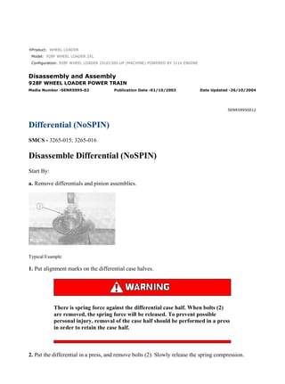
  • 1. Product: WHEEL LOADER Model: 928F WHEEL LOADER 2XL Configuration: 928F WHEEL LOADER 2XL01300-UP (MACHINE) POWERED BY 3116 ENGINE Disassembly and Assembly 928F WHEEL LOADER POWER TRAIN Media Number -SENR5995-02 Publication Date -01/10/2003 Date Updated -26/10/2004 SENR59950012 Differential (NoSPIN) SMCS - 3265-015; 3265-016 Disassemble Differential (NoSPIN) Start By: a. Remove differentials and pinion assemblies. Typical Example 1. Put alignment marks on the differential case halves. There is spring force against the differential case half. When bolts (2) are removed, the spring force will be released. To prevent possible personal injury, removal of the case half should be performed in a press in order to retain the case half. 2. Put the differential in a press, and remove bolts (2). Slowly release the spring compression. 1/4(W) w 2022/8/1 https://127.0.0.1/sisweb/sisweb/techdoc/techdoc_print_page.jsp?returnurl=/sisweb/siswe...
  • 2. 3. Remove the differential case half. 4. Remove side gear (8), spacer block (9), retainer (10), spring (11) and hold out ring and clutch assembly (12). 5. Remove spider cam assembly (6), hold out ring and clutch assembly (7), spring (13), retainer (4), and side gear (5). Assemble Differential (NoSPIN) 2/4(W) w 2022/8/1 https://127.0.0.1/sisweb/sisweb/techdoc/techdoc_print_page.jsp?returnurl=/sisweb/siswe...
  • 3. Personal injury can result from being struck by parts propelled by a released spring force. Make sure to wear all necessary protective equipment. Follow the recommended procedure and use all recommended tooling to release the spring force. 1. Put one of the case halves in a press. 2. Install side gear (5), retainer (4), spring (13), holdout ring and clutch assembly (7) and spider cam assembly (6). 3/4(W) w 2022/8/1 https://127.0.0.1/sisweb/sisweb/techdoc/techdoc_print_page.jsp?returnurl=/sisweb/siswe...
  • 4. 3. Install holdout ring and clutch assembly (12), spring (11), retainer (10), spacer block (9) and side gear (8). Typical Example 4. Install case half (3). Use press to compress the springs in the differential. Typical Example NOTICE A new differential group or a new case assembly will be equipped with four bolts and washers that are used for shipping, assembly and storage purposes only. Remove and discard these four bolts and washers after the bevel gear has been installed. These four bolts and washers should not be used for final assembly. 5. Install bolts (2) that hold the differential case halves together. End By: a. install the differential and pinion assemblies 4/4(W) w 2022/8/1 https://127.0.0.1/sisweb/sisweb/techdoc/techdoc_print_page.jsp?returnurl=/sisweb/siswe...
  • 5. Product: WHEEL LOADER Model: 928F WHEEL LOADER 2XL Configuration: 928F WHEEL LOADER 2XL01300-UP (MACHINE) POWERED BY 3116 ENGINE Disassembly and Assembly 928F WHEEL LOADER POWER TRAIN Media Number -SENR5995-02 Publication Date -01/10/2003 Date Updated -26/10/2004 SENR59950013 Engine & Transmission SMCS - 1012-029; 1013-010; 3001-029; 3153-016; 3153-015 Remove & Install Engine & Transmission Start By: a. Remove radiator and guard. b. Remove hydraulic tank**. c. Remove cab**. d. Remove steering cylinders**. e. Remove drive shaft group*. *Refer to the Power Train Disassembly & Assembly module for this information. NOTE: Identify and mark all lines, hoses and electrical wiring before removing or disconnecting for purposes of reassembly. 1/14(W) w 2022/8/1 https://127.0.0.1/sisweb/sisweb/techdoc/techdoc_print_page.jsp?returnurl=/sisweb/siswe...
  • 6. 1. Remove condenser line (2). 2. Disconnect plug connect (1). 3. Disconnect wire (3) on the solenoid. 4. Disconnect two quick connects (4). 5. Remove two fuel lines (5). 6. Remove two bolts, washers and clips (6) and reposition cable (7). 7. Loosen two clamps (8) and remove the heater lines. 8. Disconnect two spade connectors (9). 9. Remove two bolts and washers (10) and bracket (11). 2/14(W) w 2022/8/1 https://127.0.0.1/sisweb/sisweb/techdoc/techdoc_print_page.jsp?returnurl=/sisweb/siswe...
  • 7. 10. Disconnect quick connect (12) and remove air dryer (13). 11. Disconnect two ground wires (14). 12. Disconnect quick connect (15). 13. Disconnect all wires (16) from the alternator. 14. Disconnect all wires (17) from the starter and solenoid. 15. Disconnect plug connector (18) and spade connector (19). 16. Remove hydraulic line (20). 17. Disconnect quick connect (21). 18. Reposition wiring harness (22). 3/14(W) w 2022/8/1 https://127.0.0.1/sisweb/sisweb/techdoc/techdoc_print_page.jsp?returnurl=/sisweb/siswe...
  • 8. 19. Disconnect quick connect (23). 20. Disconnect six plugs (24) and reposition wire harness (25). 21. Disconnect quick connect (26) on lower right side of transmission. 22. Remove two bolts, washers and clips (27) holding parking brake (28) to the frame assembly. 23. Remove hydraulic line (29). 4/14(W) w 2022/8/1 https://127.0.0.1/sisweb/sisweb/techdoc/techdoc_print_page.jsp?returnurl=/sisweb/siswe...
  • 9. 24. Attach tool (A) to engine and transmission and a suitable lifting device. 25. Remove two mounting bolts and washers (30) holding the engine to the frame. 26. Remove eight bolts and washers (31) from brackets (32). 27. Remove two mounting bolts and washers (33) from two brackets (32). 28. Remove the engine and transmission as shown. The weight of the engine and transmission is 1362 kg (3000 lb). NOTE: Install in the reverse order. End By: a. install drive shaft* b. install steering valve and diverter valve* c. install steering cylinders** d. install radiator and guard e. install hydraulic tank** f. install cab** 5/14(W) w 2022/8/1 https://127.0.0.1/sisweb/sisweb/techdoc/techdoc_print_page.jsp?returnurl=/sisweb/siswe...
  • 10. *Refer to the Power Train Disassembly & Assembly module for this information. **Refer to the Machine Systems Disassembly & Assembly module for this information. Separate & Connect Engine From Transmission Start By: a. remove engine & transmission 1. Support transmission and engine using tooling (A) and wood blocks as shown. 2. Disconnect all wire clips and connectors. 3. Attach suitable lifting device to the transmission, remove bolts and washers (1) and separate transmission from engine. NOTE: Connect engine & transmisison in the reverse order. End By: a. install engine & transmission Separation & Connection of Torque Converter From Transmission 6/14(W) w 2022/8/1 https://127.0.0.1/sisweb/sisweb/techdoc/techdoc_print_page.jsp?returnurl=/sisweb/siswe...
  • 11. Start By: a. remove transmission 1. Thoroughly clean the outside of the transmission prior to disassembly. 2. Drain the transmission fluid into a suitable container. 3. Mark all parts and components for assembly purposes. 4. Install tool (A), chains and a suitable lifting device to transmission (1) as shown. The weight of the transmission is 700 kg (1545 lb). 5. Move the transmission to a clean safe work area and install on Tool (B) as shown. 6. Install tooling (C), chains and a suitable lifting device to transmission cover (2) as shown. NOTE: Use a bubble level to get the cover as level as possible. 7/14(W) w 2022/8/1 https://127.0.0.1/sisweb/sisweb/techdoc/techdoc_print_page.jsp?returnurl=/sisweb/siswe...
  • 12. 7. Remove twenty seven bolts (3). 8. Slowly and carefully lift the transmission cover straight up far enough to clear input shaft (4). The weight of the transmission cover is 200 kg (440 lb). NOTE: Install in the reverse order. NOTE: Use 6V6640 Gasket Maker on mating surfaces of the torque converter and the transmission. 9. Tighten twenty seven bolts (3) to the torque of 55 ± 10 N·m (40 ± 7 lb ft). Disassemble Transmission Pump 1. Remove two bolts (1) and cover (2). 2. Remove seven bolts (3). Check O-ring seal (4) for damage or wear and replace if necessary. 8/14(W) w 2022/8/1 https://127.0.0.1/sisweb/sisweb/techdoc/techdoc_print_page.jsp?returnurl=/sisweb/siswe...
  • 13. 3. Install two forcing screws as shown. 4. Use tool (A), chains and a suitable lifting device to remove gear pump group (5). 5. Remove six bolts (6). 6. Remove shaft (7). 7. Use tool (B) to remove retaining ring (8). 9/14(W) w 2022/8/1 https://127.0.0.1/sisweb/sisweb/techdoc/techdoc_print_page.jsp?returnurl=/sisweb/siswe...
  • 14. 8. Remove gear (9) and ball bearing (10) as a unit. 9. Use a suitable press to remove ball bearing (10) from gear (9). 10. Remove five bolts (11). NOTE: Only one of these bolts marked (X) has a washer. 11. Turn gear pump group (5) over and remove one bolt (12). 12. Separate pump cover assembly (13) from gear pump group (5). 13. If necessary, remove two bushings (14). 14. Check O-ring seal (15) for damage or wear and replace if necessary. 10/14(W) w 2022/8/1 https://127.0.0.1/sisweb/sisweb/techdoc/techdoc_print_page.jsp?returnurl=/sisweb/siswe...
  • 15. 15. Remove two oil pump gears (16). Mark these gears and their location for assembly purposes. 16. Check the condition of the two dowels (17) and replace if necessary. 17. Check the condition of the two dowels (18) and replace if necessary. 18. If necessary, remove two bushings (19). Assemble Transmission Pump 1. If removed, install two bushings (19). 11/14(W) w 2022/8/1 https://127.0.0.1/sisweb/sisweb/techdoc/techdoc_print_page.jsp?returnurl=/sisweb/siswe...
  • 16. 2. Install two oil pump gears (16). 3. Check the condition of two dowels (17) and replace if necessary. 4. Check the condition of two dowels (18) and replace if necessary. 5. If removed, install two bushings (14). 6. Check O-ring seal (15) for damage or wear and replace if necessary. 7. Turn gear pump group (5) over and install one bolt (12). 8. Connect pump cover assembly (13) to gear pump group (5). 9. Install five bolts (11). NOTE: Only one of these bolts marked (X) has a washer. 12/14(W) w 2022/8/1 https://127.0.0.1/sisweb/sisweb/techdoc/techdoc_print_page.jsp?returnurl=/sisweb/siswe...
  • 17. 10. Heat bearing (10) to 135°C (275°F) and install in gear (9). 11. Install gear (9) and bearing (10) as a unit. 12. Use tool (B) to install retaining ring (186). 13. Install shaft (7). 13/14(W) w 2022/8/1 https://127.0.0.1/sisweb/sisweb/techdoc/techdoc_print_page.jsp?returnurl=/sisweb/siswe...
  • 18. 14. Install six bolts (6). 15. Use tool (A), chains and a suitable lifting device to install gear pump group (5). 16. Install seven bolts (3). Check O-ring seal (4) for damage or wear and replace if necessary. 17. Install two bolts (1) and cover (2). 14/14(W) w 2022/8/1 https://127.0.0.1/sisweb/sisweb/techdoc/techdoc_print_page.jsp?returnurl=/sisweb/siswe...
  • 19. Product: WHEEL LOADER Model: 928F WHEEL LOADER 2XL Configuration: 928F WHEEL LOADER 2XL01300-UP (MACHINE) POWERED BY 3116 ENGINE Disassembly and Assembly 928F WHEEL LOADER POWER TRAIN Media Number -SENR5995-02 Publication Date -01/10/2003 Date Updated -26/10/2004 SENR59950014 Torque Converter SMCS - 3101-015; 3101-016 Disassemble Torque Converter Start By: a. remove engine, transmission and torque converter b. separation of engine from transmission and torque converter c. separation of transmission from torque converter 1. Install tool (A) as shown. 2. Remove six bolts (1). 3. Lift transmission cover (2) straight up and off the torque converter. The weight of the transmission cover if 150 kg (330 lb). 1/9(W) w 2022/8/1 https://127.0.0.1/sisweb/sisweb/techdoc/techdoc_print_page.jsp?returnurl=/sisweb/siswe...
  • 20. 4. Install tool (A) as shown. 5. Remove eighteen bolts (2) and washers. 6. Install two forcing screws as shown. 7. Separate drive gear (3) and stator carrier (4) from rotating housing (5). 8. Remove six socket head bolts (6). 9. Remove two clamp plates (7). 10. Use tool (B) to remove retaining ring (8). 2/9(W) w 2022/8/1 https://127.0.0.1/sisweb/sisweb/techdoc/techdoc_print_page.jsp?returnurl=/sisweb/siswe...
  • 21. 11. Carefully tap stator carrier (4) from converter impeller (9). 12. Check seal ring (11) for damage or wear and replace if necessary. 13. Remove twelve bolts (12). 14. Remove drive gear (3) from converter impeller (9). 15. Use a suitable press to remove ball bearing (13) from converter impeller (9). 16. Use tool (B) to remove retaining ring (14). 3/9(W) w 2022/8/1 https://127.0.0.1/sisweb/sisweb/techdoc/techdoc_print_page.jsp?returnurl=/sisweb/siswe...
  • 22. 17. Lift converter turbine (15) from rotating housing (5). 18. Remove rear bearing lock (16). 19. Remove end cover (17). 20. Turn the rotating housing over and use a soft hammer to tap splined hub and ball bearing (18) out of the housing. 4/9(W) w 2022/8/1 https://127.0.0.1/sisweb/sisweb/techdoc/techdoc_print_page.jsp?returnurl=/sisweb/siswe...
  • 23. 21. Use tool (B) to remove snap ring (19) from splined hub (18). 22. If necessary, remove ball bearing (20) from splined hub (18). 23. Check the condition of locating ring (21) on the outside diameter of ball bearing (20) and replace if necessary. 24. Check oil damn or "D" ring (22) for damage or wear and replace if necessary. Assemble Torque Converter 1. Check oil damn or "D" ring (22) for damage or wear and replace if necessary. 2. Use tool (B) to install snap ring (19) to splined hub (18). 3. If removed, install bearing (20) to splined hub (18). 4. Check the condition of locating ring (21) on the outside diameter of bearing (20) and replace if necessary. 5/9(W) w 2022/8/1 https://127.0.0.1/sisweb/sisweb/techdoc/techdoc_print_page.jsp?returnurl=/sisweb/siswe...
  • 24. 5. Turn the rotating housing over and assemble splined hub and bearing (18) to the housing. 6. Install end cover (17). 7. Install rear bearing lock (16). 8. Assemble converter turbine (15) to rotating housing (5). 9. Use tool (B) to install retaining ring (14). 6/9(W) w 2022/8/1 https://127.0.0.1/sisweb/sisweb/techdoc/techdoc_print_page.jsp?returnurl=/sisweb/siswe...
  • 25. Suggest: For more complete manuals. Please go to the home page. https://www.ebooklibonline.com If the above button click is invalid. Please download this document first, and then click the above link to download the complete manual. Thank you so much for reading
  • 26. 10. Heat bearing (13) to 135°C (275°F) and assemble to impeller (9). 11. Install drive gear (3) to impeller (9). 12. Install twelve bolts (12) and tighten to the torque of 30 ± 5 N·m (22 ± 4 lb ft). 13. Check seal ring (11) for damage or wear and replace if necessary. 14. If removed, install six spring pins (10). 15. Carefully install stator carrier (4) to impeller (9). 7/9(W) w 2022/8/1 https://127.0.0.1/sisweb/sisweb/techdoc/techdoc_print_page.jsp?returnurl=/sisweb/siswe...
  • 27. 16. Install two clamp plates (7). 17. Use tool (B) to install retaining ring (8). 18. Install six socket head bolts (6) and tighten to the torque of 30 ± 5 N·m (22 ± 4 lb ft). 19. Assemble drive gear (3) and stator carrier (4) to rotating housing (5). 20. Install tool (A) as shown. 21. Install eighteen bolts (2) and the washers and tighten to a torque of 30 ± 5 N·m (22 ± 4 lb ft). 8/9(W) w 2022/8/1 https://127.0.0.1/sisweb/sisweb/techdoc/techdoc_print_page.jsp?returnurl=/sisweb/siswe...