Download to read offline


![FeaturesSpecificationsTerminalFunctionsExternalDimensions
FUJI ELECTRIC INVERTERS
High Perfomance Compact Body Welcome to the NEXT Generation of Compact Inverters
· PC loader software available as a free download
Note: Three-phase 200V 0.1–0.75kW dimensions shown (mm(inch))
High Performance and Multipurpose
Full Compatibility and User Friendly Design
Easy Operation and Maintenance
Dynamic Torque Vector Control System
Fuji Electric original dynamic torque vector control system is known for its
top-of-the line performance, delivering stabile torque output even at low
speeds. This feature has a wide range of applications, including conveyors
and high-inertia loads that demand high starting torque.
Function
Mock malfunction
Number of startups
Cumulative motor running time
Total power
Trip history
Select a function to set off a mock alarm
Count the total number of ON/OFF run cycles
Monitor motor run time
Set to measure total power consumption
Saves and displays information on up to four past trips
Description
External dimensions
Installed dimensions
Number of terminals
Terminal position
Function codes
RS-485 communication
Interchangeable
Interchangeable
Same for both main circuit and controllers
Compatible terminal wire length
Compatible function codes
Shared communications protocol
Slip Compensation shortens setting time
The slip compensation controller works with voltage tuning for even more
accurate speed control at low velocity. This reduces speed control variability
and stabilizing creep speed for more accurate stopping in conveyors and
similar equipment.
Fastest CPU Processor in its Class
Advanced CPU processes data at twice the speed of our current model
Usability
Delivers all the usability of the C1. Provides volume of frequency
and the same ease of operation as the current model.
Improve Maintainability
USB Keypad
Optional USB keypad available. Enhanced PC loader connectivity.
LAN cable
USB-USB mini-B cable
120
(4.72)
120
(4.72)
80(3.15) 80(3.15)
Current C1 model New C2 model
200
100
0
-100
-200
Outputtorque[%]
Motor
speed
[r/min]
10Hz
5Hz
3Hz
3](https://image.slidesharecdn.com/frenic-minic2catalog-141130200805-conversion-gate01/75/Bi-n-t-n-FRENIC-Mini-Catalog-4-2048.jpg)

![FeaturesSpecificationsTerminalFunctionsExternalDimensions
FUJI ELECTRIC INVERTERS
High Perfomance Compact Body Welcome to the NEXT Generation of Compact Inverters
Standard specifications
Without EMC filter type
0.1 [1/8]
0.2 [1/4]
0.4 [1/2]
0.75 [1]
1.5 [2]
2.2 [3]
3.7 [5]
5.5 [7.5]
7.5 [10]
11 [15]
15 [20]
Destination
FRN0001C2S-2
FRN0002C2S-2
FRN0004C2S-2
FRN0006C2S-2
FRN0010C2S-2
FRN0012C2S-2
FRN0020C2S-2
FRN0025C2S-2
FRN0033C2S-2
FRN0047C2S-2
FRN0060C2S-2
A(Asia), U(USA)
FRN0002C2S-4
FRN0004C2S-4
FRN0005C2S-4
FRN0007C2S-4
FRN0011C2S-4
FRN0013C2S-4
FRN0018C2S-4
FRN0024C2S-4
FRN0030C2S-4
FRN0001C2S-7
FRN0002C2S-7
FRN0004C2S-7
FRN0006C2S-7
FRN0010C2S-7
FRN0012C2S-7
FRN0001C2S-6U
FRN0002C2S-6U
FRN0003C2S-6U
FRN0005C2S-6U
U(USA)
Code
FRN
Series Name
FRENIC series
Code
A
C
E
U
Destination/Manual
Asia/English
China/Chinese
Europe/English
USA/English
Code
2
4
6
7
Input Power Source
Three-phase 200V
Three-phase 400V
Single-phase 100V
Single-phase 200V
Applicable Current Rating
This value shows an amperage rating
0001∼0060
Code
C
Application Range
Compact
Code
S
E
Enclosure
Standard (IP20) (UL Open Type)
EMC filter built-in type
Code
2
Developed Inverter Series
2-series
A(Asia), C(China), E(Europe), U(USA)
Semi-standard specifications
EMC filter built-in type
0.1 [1/8]
0.2 [1/4]
0.4 [1/2]
0.75 [1]
1.5 [2]
2.2 [3]
3.7 [5]
5.5 [7.5]
7.5 [10]
11 [15]
15 [20]
Destination
FRN0002C2E-4
FRN0004C2E-4
FRN0005C2E-4
FRN0007C2E-4
FRN0011C2E-4
FRN0013C2E-4
FRN0018C2E-4
FRN0024C2E-4
FRN0030C2E-4
FRN0001C2E-7
FRN0002C2E-7
FRN0004C2E-7
FRN0006C2E-7
FRN0010C2E-7
FRN0012C2E-7
C(China), E(Europe)
Variation
How To Read Model Number
FRN 0010 C 2 S - 4 A
Caution
The contents of this catalog are provided to help you select the product model that is best for you. Before actual use, be sure to read the User’s Manual
thoroughly to assure correct operation.
Nominal Applied
Motor (kW)[HP]
Three-phase
200V series
Three-phase
400V series
Single-phase
200V series
Single-phase
100V series
Coming Soon
5](https://image.slidesharecdn.com/frenic-minic2catalog-141130200805-conversion-gate01/75/Bi-n-t-n-FRENIC-Mini-Catalog-6-2048.jpg)

Nominal applied motor[HP]( =U)
Applicable safety standards
Enclosure (IEC 60529)
Cooling method
Weight / Mass[kg(Ibs)]
0002
0.2
1/4
0.57
1.5(1.4)
0.93
1.8
0.3
0.6(1.3)
0004
0.4
1/2
1.3
3.5(2.5)
1.6
3.1
0.6
0.7(1.5)
0006
0.75
1
2.0
5.5(4.2)
3.0
5.3
1.1
0.8(1.8)
0010
1.5
2
3.5
9.2(7.0)
5.7
9.5
2.0
1.7(3.7)
100
Built-in
50
Fan cooling
30
0012
2.2
3
4.5
12.0(10.0)
8.3
13.2
2.9
1.7(3.7)
0020
3.7
5
7.2
19.1(16.5)
14.0
22.2
4.9
2.5(5.5)
0025
5.5
7.5
9.5
25.0(23.5)
21.1
31.5
7.4
3.1(6.8)
0033
7.5
10
12
33.0(31.0)
28.8
42.7
10
3.1(6.8)
0047
11
15
17
47.0(44.0)
42.2
60.7
15
4.5(9.8)
0060
15
20
22
60.0(57.0)
57.6
80.0
20
4.5(9.8)
Three-phase 200V
FRN C2S-2A, FRN C2S-2U
Three-phase 200 to 240V (With AVR)
150% of rated current for 1min
150% of rated current for 1min or 200% of rated current for 0.5s (If the rated current is in parenthesis)
50, 60Hz
Three-phase, 200 to 240V, 50/60Hz
Voltage: +10 to -15% (Voltage unbalance : 2% or less), Frequency: +5 to -5%
150
Starting frequency: 0.0 to 60.0Hz, Braking time: 0.0 to 30.0s Braking level: 0 to 100%
−
UL508C, EN 61800-5-1:2007
IP20 (IEC 60529:1989) / UL open type (UL50)
Natural cooling
150% of rated current for 1min or
200% of rated current for 0.5s
20
0001
0.1
1/8
0.30
0.8(0.7)
0.57
1.1
0.2
0.6(1.3)
Item Specifications
OutputratingsInputratingsBraking
Rated capacity[kVA]
Rated voltage[V]
Rated current[A](*1)
Overload capability
Rated frequency[Hz]
Phases, Voltage, Frequency
Voltage/Frequency variations
Rated current[A]
Required power supply capacity[kVA]
Torque[%]
DC injection braking
Braking transistor
Three-phase 200V series
*1 The load shall be reduced so that the continuous operating current is the rated current in parenthesis or less if the carrier frequency is set to 3kHz or above or ambient temperature exceeds 40℃ (104℉).
50
Fan cooling
30
150% of rated current for 1min or
200% of rated current for 0.5s
20
(with DCR)
(without DCR)
Input power source
Type
(FRN C2S-4 , =A, C, E, U)
Nominal applied motor[kW]
( =A, C, E)
Nominal applied motor[HP]( =U)
Applicable safety standards
Enclosure (IEC 60529)
Cooling method
Weight / Mass[kg(Ibs)]
0011
3.7( =A, C)
4.0( =E)
5
8.0
10.5(9.0)
7.3
13.0
4.9
2.5(5.5)
0013
5.5
7.5
9.9
13.0
10.6
17.3
7.4
3.1(6.8)
0018
7.5
10
13
18.0
14.4
23.2
10
3.1(6.8)
0024
11
15
18
24.0
21.1
33.0
15
4.5(9.8)
0030
15
20
22
30.0
28.8
43.8
20
4.5(9.8)
0007
2.2
3
4.8
6.3(5.5)
4.4
8.2
2.9
1.7(3.7)
0005
1.5
2
3.2
4.3(3.7)
3.0
5.9
2.0
1.7(3.7)
0004
0.75
1
2.3
3.1(2.5)
1.6
3.1
1.1
1.3(2.9)
0002
0.4
1/2
1.3
1.8(1.5)
0.85
1.7
0.6
1.2(2.6)
Three-phase 400V
FRN C2S-4A, FRN C2S-4C
FRN C2S-4E, FRN C2S-4U
Three-phase 380 to 480V (With AVR)
150% of rated current for 1min
150% of rated current for 1min or 200% of rated current for 0.5s (If the rated current is in parenthesis)
50, 60Hz
Three-phase, 380 to 480V, 50/60Hz
Voltage: +10 to -15% (Voltage unbalance : 2% or less), Frequency: +5 to -5%
100
Starting frequency: 0.0 to 60.0Hz, Braking time: 0.0 to 30.0s Braking level: 0 to 100%
Built-in
UL508C, EN 61800-5-1:2007
IP20 (IEC 60529:1989) / UL open type (UL50)
Natural cooling
Item Specifications
OutputratingsInputratingsBraking
Rated capacity[kVA]
Rated voltage[V]
Rated current[A](*1)
Overload capability
Rated frequency[Hz]
Phases, Voltage, Frequency
Voltage/Frequency variations
Rated current[A]
Required power supply capacity[kVA]
Torque[%]
DC injection braking
Braking transistor
Three-phase 400V series
*1 The load shall be reduced so that the continuous operating current is the rated current in parenthesis or less if the carrier frequency is set to 3kHz or above or ambient temperature exceeds 40℃ (104℉).
6](https://image.slidesharecdn.com/frenic-minic2catalog-141130200805-conversion-gate01/75/Bi-n-t-n-FRENIC-Mini-Catalog-7-2048.jpg)
![FeaturesSpecificationsTerminalFunctionsExternalDimensions
FUJI ELECTRIC INVERTERS
High Perfomance Compact Body Welcome to the NEXT Generation of Compact Inverters
Specifications
50
Fan cooling
30
Single-phase 100V
FRN C2S-6U
150% of rated current for 1min
or 200% of rated current for 0.5s
Single-phase 100 to 120V, 50/60Hz
150
−
UL508C
Natural cooling
(with DCR)
(without DCR)
Input power source
Type
(FRN C2S- , =A, C, E, U)
Nominal applied motor[kW]
( =A, C, E)
Nominal applied motor[HP]( =U)
Applicable safety standards
Enclosure (IEC 60529)
Cooling method
Weight / Mass[kg(Ibs)]
0002
0.2
1/4
0.57
1.5(1.4)
2.0
3.3
0.4
0.6(1.3)
0004
0.4
1/2
1.3
3.5(2.5)
3.5
5.4
0.7
0.7(1.5)
0006
0.75
1
2.0
5.5(4.2)
6.4
9.7
1.3
0.9(2)
0010
1.5
2
3.5
9.2(7.0)
11.6
16.4
2.4
1.8(4)
0012
2.2
3
4.5
12.0(10.0)
17.5
24.0
3.5
2.5(5.5)
0002
0.2
1/4
0.53
1.4
3.8
5.9
0.5
0.7(1.5)
0003
0.4
1/2
0.95
2.5
6.4
9.5
0.7
0.8(1.8)
0005
0.75
1
1.6
4.2
12.0
16.0
1.3
1.3(2.9)
0001
0.1
1/8
0.26
0.7
2.2
3.6
0.3
0.7(1.5)
100
Built-in
100
Built-in
Single-phase 200V
FRN C2S-7A, FRN C2S-7C
FRN C2S-7E, FRN C2S-7U
Three-phase 200 to 240V (With AVR)
150% of rated current for 1min
150% of rated current for 1min or 200% of rated current for 0.5s (If the rated current is in parenthesis)
50, 60Hz
Single-phase, 200 to 240V, 50/60Hz
Voltage: +10 to -10%, Frequency: +5 to -5%
150
Starting frequency: 0.0 to 60.0Hz, Braking time: 0.0 to 30.0s, Braking level: 0 to 100%
−
UL508C, EN 61800-5-1:2007
IP20 (IEC 60529:1989) / UL open type (UL50)
Natural cooling
0001
0.1
1/8
0.30
0.8(0.7)
1.1
1.8
0.3
0.6(1.3)
Item Specifications
OutputratingsInputratingsBraking
Rated capacity[kVA]
Rated voltage[V]
Rated current[A](*1)
Overload capability
Rated frequency[Hz]
Phases, Voltage, Frequency
Voltage/Frequency variations
Rated current[A]
Required power supply capacity[kVA]
Torque[%]
DC injection braking
Braking transistor
*1 The load shall be reduced so that the continuous operating current is the rated current in parenthesis or less if the carrier frequency is set to 3kHz or above or ambient temperature exceeds 40℃ (104℉).
Single-phase 200V/100V series
7](https://image.slidesharecdn.com/frenic-minic2catalog-141130200805-conversion-gate01/75/Bi-n-t-n-FRENIC-Mini-Catalog-8-2048.jpg)

Nominal applied motor[HP]
Applicable safety standards
Enclosure (IEC 60529)
Cooling method
Weight / Mass[kg(Ibs)]
0011
3.7( =A, C)/4.0( =E)
5
8.0
10.5(9.0)
7.3
13.0
4.9
3.0(6.6)
0007
2.2
3
4.8
6.3(5.5)
4.4
8.2
2.9
2.5(5.5)
0005
1.5
2
3.2
4.3(3.7)
3.0
5.9
2.0
2.5(5.5)
0004
0.75
1
2.3
3.1(2.5)
1.6
3.1
1.1
1.6(3.5)
50
Fan cooling
30
0002
0.4
1/2
1.3
1.8(1.5)
0.85
1.7
0.6
1.5(3.3)
Three-phase 400V
FRN C2E-4C, FRN C2E-4E
Three-phase 380 to 480V (With AVR)
150% of rated current for 1min
150% of rated current for 1min or 200% of rated current for 0.5s (If the rated current is in parenthesis)
50, 60Hz
Three-phase, 380 to 480V, 50/60Hz
Voltage: +10 to -15% (Voltage unbalance : 2% or less), Frequency: +5 to -5%
100
Starting frequency: 0.0 to 60.0Hz, Braking time: 0.0 to 30.0s Braking level: 0 to 100%
Built-in
UL508C, EN 61800-5-1:2007
Immunity : Second Environment (Industrial)
Emission : Category C2
IP20 (IEC 60529:1989) / UL open type (UL50)
Natural cooling
Item Specifications
OutputratingsInputratingsBraking
Rated capacity[kVA]
Rated voltage[V]
Rated current[A](*1)
Overload capability
Rated frequency[Hz]
Phases, Voltage, Frequency
Voltage/Frequency variations
Rated current[A]
Required power supply capacity[kVA]
Torque[%]
DC injection braking
Braking transistor
Three-phase 400V series
*1 The load shall be reduced so that the continuous operating current is the rated current in parenthesis or less if the carrier frequency is set to 3kHz or above or ambient temperature exceeds 40℃ (104℉).
(with DCR)
(without DCR)
Input power source
Type
(FRN C2E-7 , =C, E)
Nominal applied motor[kW]( =C, E)
Nominal applied motor[HP]
Applicable safety standards
Enclosure (IEC 60529)
Cooling method
Weight / Mass[kg(Ibs)]
0002
0.2
1/4
0.57
1.5(1.4)
2.0
3.3
0.4
0.7(1.5)
0004
0.4
1/2
1.3
3.5(2.5)
3.5
5.4
0.7
0.7(1.5)
0006
0.75
1
2.0
5.5(4.2)
6.4
9.7
1.3
1.2(2.6)
0010
1.5
2
3.5
9.2(7.0)
11.6
16.4
2.4
2.4(5.3)
0012
2.2
3
4.5
12.0(10.0)
17.5
24.0
3.5
2.9(6.4)
100
Built-in
Single-phase 200V
FRN C2E-7C, FRN C2E-7E
Single-phase, 200 to 240V, 50/60Hz
150% of rated current for 1min
150% of rated current for 1min or 200% of rated current for 0.5s (If the rated current is in parenthesis)
50, 60Hz
Single-phase, 200 to 240V, 50/60Hz
Voltage: +10 to -10%, Frequency: +5 to -5%
150
Starting frequency: 0.0 to 60.0Hz, Braking time: 0.0 to 30.0s, Braking level: 0 to 100%
−
UL508C, EN 61800-5-1:2007
Immunity : Second Environment (Industrial)
Emission : Category C2
IP20 (IEC 60529:1989) / UL open type (UL50)
Natural cooling
0001
0.1
1/8
0.30
0.8(0.7)
1.1
1.8
0.3
0.7(1.5)
Item Specifications
OutputratingsInputratingsBraking
Rated capacity[kVA]
Rated voltage[V]
Rated current[A](*1)
Overload capability
Rated frequency[Hz]
Phases, Voltage, Frequency
Voltage/Frequency variations
Rated current[A]
Required power supply capacity[kVA]
Torque[%]
DC injection braking
Braking transistor
*1 The load shall be reduced so that the continuous operating current is the rated current in parenthesis or less if the carrier frequency is set to 3kHz or above or ambient temperature exceeds 40℃ (104℉).
Single-phase 200V series
Applicable EMC standards
(EN61800-3:2004 +A1:2012)
(in progress)
Applicable EMC standards
(EN61800-3:2004 +A1:2012)
(in progress)
8](https://image.slidesharecdn.com/frenic-minic2catalog-141130200805-conversion-gate01/75/Bi-n-t-n-FRENIC-Mini-Catalog-9-2048.jpg)
![FeaturesSpecificationsTerminalFunctionsExternalDimensions
FUJI ELECTRIC INVERTERS
High Perfomance Compact Body Welcome to the NEXT Generation of Compact Inverters
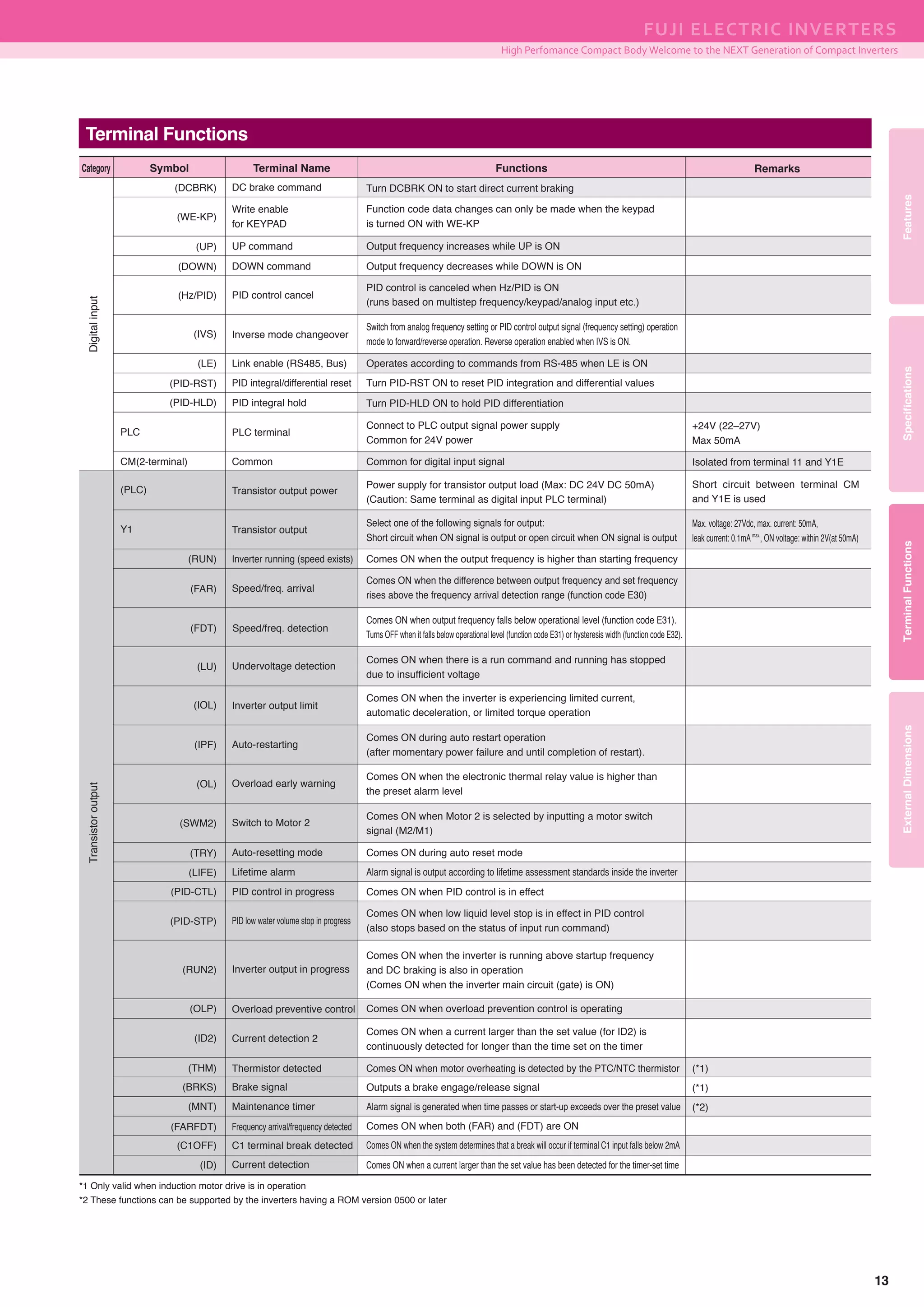
*1 Only valid when induction motor drive is in operation
Common Specifications
Common Specifications
Maximum frequency
Base frequency
Starting frequency
Carrier frequency
Accuracy (stability)
Setting resolution
Control method
Voltage/freq. characteristic
Torque boost (*1)
Start/stop
Frequency setting
Acceleration/deceleration time
Starting torque (*1)
25 to 400Hz
· Automatic torque boost (for constant torque loads)
· Manual torque boost: Optional torque boost value can be set between 0.0 and 20.0%
· Application load can be selected (for constant and variable torque loads)
150% or more/frequency set to 3Hz Slip compensation /automatic torque boost active
25 to 400Hz
0.1 to 60.0Hz
0.75 to 16kHz
Note: The unit is equipped with an automatic reduction/stop function that may automatically drop the carrier frequency to
protect the inverter when it is running at frequencies above 6 kHz, depending on ambient temperature, output current, and
other conditions. (*1)
· Under modulated carrier conditions, the system scatters carrier frequency to reduce noise
Induction motor drive
· V/f control · Slip compensation · Automatic torque boost
· Dynamic torque vector control · Automatic energy-saving function
· Analog setting : 1/1000 of maximum frequency
· Keypad setting : 0.01Hz (99.99Hz or less), 0.1Hz (100.0Hz to 400.0Hz)
· Link operation : 1/20000 of maximum frequency or 0.01Hz (fixed)
· Analog setting: : Absolute accuracy within ± 2% (at 25℃(77℉)), temperature drift within ± 0.2% (25℃(77℉) ± 10℃(50℉))
· Keypad setting: : Absolute accuracy within ± 0.01% (at 25℃(77℉)), temperature drift within ± 0.01% (25℃(77℉) ± 10℃(50℉))
200V series
Base frequency and maximum output frequency can each be set between :80 to 240
AVR control (*1) can be turned ON or OFF
Allowable non-linear V/f (*1) settings (2): optional voltage (0–240V) and frequency (0–400Hz)
400V series
Base frequency and maximum output frequency can each be set between :160 to 500
AVR control (*1) can be turned ON or OFF
Allowable non-linear V/f (*1) settings (2): optional voltage (0–500V) and frequency (0–400Hz)
Synchronous motor drive
· Sensorless magnetic positioning (speed control range: 10% of base frequency and up)
OutputfrequencyControl
Settingrange
Keypad operation : Start and stop with , keys (standard keypad)
: Start and stop with , keys (remote keypad: optional)
External signals : FWD (REV) operation/stop command [3-wire operation enabled]
(digital input) Coast-to-stop command, trip command (external fault), fault reset, etc.
Link operation : Communication via RS-485
Multistep frequency : Selectable from 16 steps (step 0 to 15)
UP/DOWN operation : Raises or lowers frequency while digital input signal is ON
Changing run command: Communications used to change run command
Keypad operation : Can be set with or key (with save data function)
Also can be set with function code (only via communication) and be copied.(*2)
Link operation: : Frequency set through RS-485 communication
· Can be set between 0.00 and 3600s
· There are two independent settings that can be selected for acceleration/deceleration time (can be switched while running)
· Pattern : The following four acceleration/deceleration types can be selected
Linear, S-curve (weak/strong), non-linear (constant output maximum capacity acceleration/deceleration)
· Coast-to-stop acceleration/deceleration is enabled when run commands are OFF
· Acceleration/deceleration time can be set during jogging operation (between 0.00 and 3600s)
Changing frequency settings
Inverse operation
Set based on built-in volume
Analog input
: 0 to +10V DC/0 to 100% (terminal 12)
: 4 to +20mA DC/0 to 100%, 0 to +20mA DC/0 to 100% (terminal C1)
: Two types of frequency settings can be changed using external signals (digital input) : frequency
settings and multistep frequency settings
Auxiliary frequency setting : Built-in potentiometer, Inputs at terminal 12, C1 can be added to the main setting as auxiliary frequency settings.
: Can be switched from (DC 0 to +10V/0 to 100%) to (DC +10 to 0V/0 to 100%) externally
: Can be switched from (DC 4 to 20mA (DC 0–20mA)/0 to 100%) to (DC 20 to 4mA (DC 20–0mA)/0 to 100%) externally
Item Explanation Remarks
9](https://image.slidesharecdn.com/frenic-minic2catalog-141130200805-conversion-gate01/75/Bi-n-t-n-FRENIC-Mini-Catalog-10-2048.jpg)
![COMPACT INVERTER FRENIC-
Common Specifications
Common Specifications
ControlIndication
Gain for frequency setting Analog input gain can be set between 0 and 200%
Bias frequency Bias of set frequency and PID command can be set separately between 0 and ±100%
Jump frequency control
Three operation points and their common jump hysteresis width can be set (0–30Hz)
Six operation points and their common jump hysteresis width can be set (0–30Hz) (*2)
Timer operation Operation starts and stops at the time set from keypad (1 cycle)
Jogging operation (*1)
Operated using the key (on the standard or remote keypad) or digital contact point input
(acceleration and deceleration time--same duration used only for jogging)
Auto-restart after momentary
power failure (*1)
・Trip at power failure: The inverter trips immediately after power failure.
・Trip at power recovery: Coast-to-stop at power failure and trip at power recovery
・Deceleration stop: Deceleration stop at power failure, and trip after stoppage (*2)
・Start at the frequency selected before momentary stop: Coast-to-stop at power failure and start after power recovery at
the frequency selected before momentary stop.
・Start at starting frequency: Coast-to-stop at power failure and start at the starting frequency after power recovery.
Current limit
by hardware (*1)
Uses hardware to limit current and prevent overcurrent trips resulting from sudden load changes, momentary power failures,
and similar events that cannot be handled by software current limiters (can be canceled)
Slip compensation (*1) Compensates for decrease in speed according to the load, enabling stable operation
Energy saving operation (*1)
Overload prevention control
Restricts output voltage to minimize total motor and inverter loss during constant speed operation
Offline tuning (*1)
Fan stop operation
Performs r1, Xσ, and excitation current tuning
Performs r1, Xσ, slip frequency and excitation current tuning (*2)
Detects inverter internal temperature and stops cooling fan when the temperature is low
Secondary motor settings
· Switching between two motors in the same inverter is enabled (switching cannot be performed while the inverter is running)
Induction motor settings can only be applied to the second motor
Data settings (base frequency, rated current, torque boost, electronic thermal, and slip compensation, etc.) can be entered for the second motor
· Constants can be set within the second motor. Auto-tuning is also enabled.
Rotational direction limits Select either prevent reverse or prevent forward operation
Lifetime alarm Displays the lifetime alarm for the main circuit condenser, PCB condenser, and cooling fan. External output is enabled for lifetime alarm information.
Total running time Can display total motor running time, total inverter running time, and total power use
I/O check Displays control circuit terminal output status
Trip history: Saves and displays the last 4 trip codes and their detailed description
Saves and displays detailed data for each section on up to four past trips
Energy saving monitor Power consumption, power consumption x coefficient
Trip mode
Running or Trip mode
Running/stopping
Speed monitor, output current [A], output voltage [V], input power [kW], PID reference, PID feedback value, PID output, timer
value (for timer operation) [s], total power amount
Select the speed monitor to be displayed from the following:
Output frequency (before slip compensation) [Hz], output frequency (after slip compensation) [Hz], set frequency [Hz],
load shaft speed [min-1
], line speed [m/min], constant rate of feeding time [min]
Lowers frequency when IGBT junction temperature and ambient temperature rise due to overloading to avoid further overload
Current limit Keeps the current under the preset value during operation
PID control
Automatic deceleration
Process PID regulator
· PID command, keyboard, analog input (terminal 12, C1), RS-485 communication
· Feedback value: Analog input (terminal 12, C1)
· Low liquid level stop function · Switch forward/reverse operation · Integration reset/hold function
Deceleration characteristics
(improved braking capacity)
Increases motor loss and reduces energy generated by the inverter during deceleration to avoid overcurrent trips
· Automatically limits output frequency, limits energy generated by the inverter, and avoids overcurrent trips when torque relay value is exceeded (*1)
· Makes deceleration time three times longer to avoid trip when DC link circuit voltage exceeds overage limit
Displays cause of trip:
· : Overcurrent during acceleration · : Overcurrent during deceleration · : Overcurrent at constant speed
· : Input phase loss · : Undervoltage · : Output phase loss
· : Overvoltage during acceleration · : Overvoltage during deceleration · : Overvoltage during constant speed
· : Overheating of the heat sink · : External thermal relay tripped · : Motor protection (PTC thermistor)
· : Overheating of the DB circuit · : PID feedback break detected · : Overload in motor 1
· : Overload in motor 2 · : Inverter unit overload · : Memory error
· : Keypad communication error · : CPU error · : Operation procedure error
· : Tuning error · : RS485 error · : Data save error due to undervoltage
· : Step out detected (for synchronous motor drive) (*2) · : Mock error
Item Explanation Remarks
*1 Only valid when induction motor drive is in operation
*2 These functions can be supported by the inverters having a ROM version 0500 or later
Frequency limiter
(Peak/bottom frequency limit)
High and low limiters can be set in addition to Hz values (0–400Hz)
10](https://image.slidesharecdn.com/frenic-minic2catalog-141130200805-conversion-gate01/75/Bi-n-t-n-FRENIC-Mini-Catalog-11-2048.jpg)


![COMPACT INVERTER FRENIC-
16
Standard Model
Fig. 2
[Unit : mm(inch)]
[Unit : mm(inch)]
[Unit : mm(inch)]
[Unit : mm(inch)] [Unit : mm(inch)]
6(0.24)
6(0.24)
1.5(0.06)
Rating plate
D
D1 D22.2(0.09)
110(4.33)
97(3.82)
6.5
(0.26)
6.5
(0.26)
7(0.28)
130(5.12)
116(4.57)6(0.24)6(0.24)
5(0.2)
4(0.16)X5(0.2)X6(0.24)
(Long hole)
D
D1 D2
2.2
(0.09)
Rating plate
140(5.51)
128(5.04)6(0.24) 6(0.24)
180(7.09)
168(6.61)6(0.24)
5(0.2)
5
(0.2)
6
(0.24)
2×φ5(0.2)
2.2(0.09)
Rating plate
D
D1 D2
External Dimensions
67(2.64)
80(3.15)
6.5(0.26) 6.5(0.26)
4(0.16)X5(0.2)X6(0.24)
(Long hole)
6(0.24)
110(4.33)5(0.2)5(0.2)
5(0.2)
120(4.72)
Fig. 1
Fig. 4Fig. 3
D
D1 D22.2(0.09)
Rating plate
3(0.12)
97(3.82)
110(4.33)
6.5(0.26) 6.5(0.26)
7(0.28)
6(0.24)
5(0.2)
118(4.65)
130(5.12)
6(0.24)
4(0.16)X5(0.2)X6(0.24)
(Long hole)
[Unit : mm(inch)]
FRN0002C2S-4
FRN0004C2S-4
FRN0005C2S-6U
Power supply
voltage Inverter type
D D1
Dimensions (mm(inch))
D2
Three-phase
400V
Single-phase
100V
115(4.53) 40(1.57)
139(5.47) 64(2.52)
75(2.95)
139(5.47) 40(1.57)99(3.9)
Three-phase
400V
149(5.87) 85(3.35)
FRN0010C2S-2
FRN0012C2S-2
FRN0005C2S-4
FRN0007C2S-4
FRN0010C2S-7
Power supply
voltage Inverter type
D D1
Dimensions (mm(inch))
D2
Single-phase
200V
139(5.47)
64(2.52)
75(2.95)
Three-phase
200V
FRN0001C2S-2
FRN0002C2S-2
FRN0004C2S-2
FRN0006C2S-2
FRN0001C2S-7
FRN0002C2S-7
FRN0004C2S-7
FRN0006C2S-7
FRN0001C2S-6U
FRN0002C2S-6U
FRN0003C2S-6U
Power supply
voltage Inverter type
D D1
Dimensions (mm(inch))
D2
Three-phase
200V
80(3.15)
95(3.74)
120(4.72)
10(0.39)
25(0.98)
50(1.97)
70(2.76)
80(3.15)
95(3.74)
140(5.51)
10(0.39)
25(0.98)
50(1.97)
70(2.76)
100(3.94)
115(4.53)
10(0.39)
25(0.98)
90(3.54)
90(3.54)
Single-phase
200V
Single-phase
100V
FRN0020C2S-2
FRN0011C2S-4
FRN0012C2S-7
Power supply
voltage Inverter type
D D1
Dimensions (mm(inch))
D2
139(5.47) 64(2.52)75(2.95)Three-phase
400V
Single-phase
200V
Three-phase
200V
Fig. 6Fig. 5
158(6.22)
87.7(3.45)
5(0.2)
180(7.09)
164(6.46)8(0.32) 8(0.32)
6(0.24)
220(8.66)
205(8.07)8(0.32)
10(0.39)
7(0.28)
2xφ6(0.24)
190(7.48)
90(3.54)
11.2(0.44)
220(8.66)
196(7.72)12(0.47) 12(0.47)
10(0.39)
260(10.24)
238(9.37)10(0.39)
11(0.43)
11(0.43)
2xφ10(0.39)
Three-phase
400V
Power supply
voltage Inverter type
Three-phase
200V
FRN0025C2S-2
FRN0033C2S-2
FRN0013C2S-4
FRN0018C2S-4
Three-phase
400V
Power supply
voltage Inverter type
Three-phase
200V
FRN0047C2S-2
FRN0060C2S-2
FRN0024C2S-4
FRN0030C2S-4](https://image.slidesharecdn.com/frenic-minic2catalog-141130200805-conversion-gate01/75/Bi-n-t-n-FRENIC-Mini-Catalog-17-2048.jpg)
![FeaturesSpecificationsTerminalFunctionsExternalDimensions
FUJI ELECTRIC INVERTERS
High Perfomance Compact Body Welcome to the NEXT Generation of Compact Inverters
17
Fig. 2
EMC Filter Built-in Model
[Unit : mm(inch)]
[Unit : mm(inch)]
Single-phase
200V
FRN0001C2E-2
FRN0002C2E-2
FRN0004C2E-2
FRN0006C2E-2
FRN0001C2E-7
FRN0002C2E-7
FRN0004C2E-7
Power supply
voltage Inverter type
D D1 D2 D3
Dimensions (mm(inch))
Three-phase
200V
100(3.94) 10(0.39) 21.2(0.83)
90
(3.54)115(4.53) 25(0.98) 36.2(1.43)
140(5.51) 50(1.97) 61.2(2.41)
100(3.94) 10(0.39) 21.2(0.83)90
(3.54)
115(4.53) 25(0.98) 36.2(1.43)
Fig. 1
Fig. 3
[Unit : mm(inch)]
Power supply
voltage Inverter type
D D1 D2 D3W2W1
Dimensions (mm(inch))
Three-phase
400V
Single-phase
200V
158(6.22) 40(1.57) 61.5(2.42)
182(7.17) 64(2.52) 85.5(3.37)
139(5.47) 40(1.57)13.0(0.51)60(2.36) 99(3.9) 55.2(2.17)
118(4.65)89(3.5) 10.5(0.41)
FRN0002C2E-4
FRN0004C2E-4
FRN0006C2E-7
Three-phase
400V
Power supply
voltage Inverter type
Single-phase
200V
Three-phase
200V
FRN0010C2E-2
FRN0012C2E-2
FRN0020C2E-2
FRN0005C2E-4
FRN0007C2E-4
FRN0011C2E-4
FRN0010C2E-7
FRN0012C2E-7
6(0.24)
2.2(0.09)
182(7.17)
118(4.65) 64(2.52)
85.5(3.37)
Rating plate
140(5.51)
6(0.24)
6
(0.24) 128(5.04)
2×φ5(0.2)
6(0.24)168(6.61)6(0.24)
10.5(0.41) 92(3.62) 27(1.06)
245(9.65)
180(7.09)
5(0.2)
97(3.82) 6.5(0.26)6.5(0.26)
7(0.28)
110(4.33)
4(0.16)X5(0.2)X6(0.24)
(Long hole)
116(4.57)
130(5.12)
180(7.09)
6(0.24)6(0.24)
5(0.2)
W1W2
3(0.12)
D3
D2D1
D
2.2(0.09)
Rating plate
2.2(0.09) D1 D2
D
D3
Rating plate
80(3.15)
120(4.72)
170(6.69)
10(0.39) 60(2.36)
67(2.64) 6.5(0.26)
6(0.24)
5(0.2)
5(0.2)5(0.2)110(4.33)
4(0.16)X5(0.2)X6(0.24)
(Long hole)
6.5(0.26)
1.5(0.06)](https://image.slidesharecdn.com/frenic-minic2catalog-141130200805-conversion-gate01/75/Bi-n-t-n-FRENIC-Mini-Catalog-18-2048.jpg)


The document introduces the next generation of compact inverters from Fuji Electric, highlighting their high performance, compact design, and user-friendly features. These inverters are compatible with various devices, offering energy efficiency, easy maintenance, and advanced control capabilities. Key specifications include dynamic torque vector control, global compatibility, and optional enhanced connectivity options.


