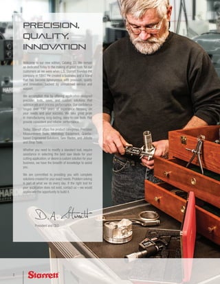
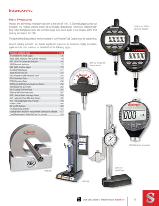
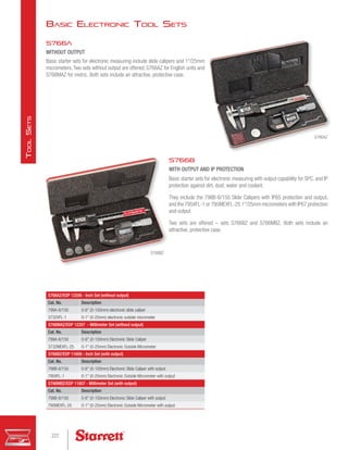
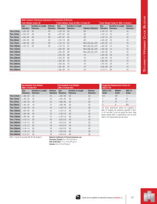
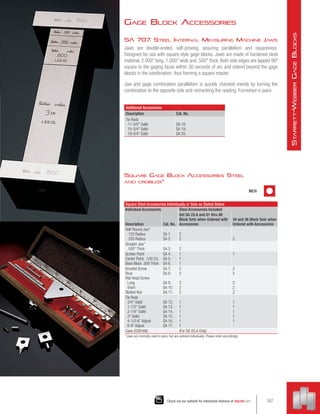
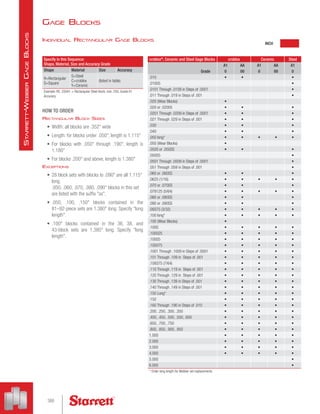
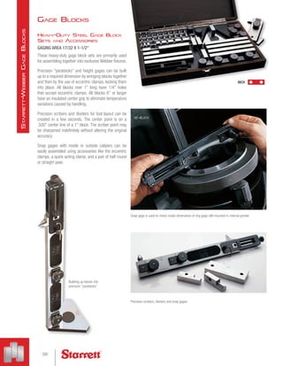
This catalog from Starrett provides an overview of their precision measurement tools and products. It includes sections on micrometers, calipers, height gages, depth gages, indicators and gages, bore gages, tool sets, data collection systems, hardness and surface testers, special gaging, squares, rules, protractors, calipers and dividers, hole and slot gages, fixed gage standards, precision shop tools, machinists' levels, gage blocks, granite surface plates, vision systems, optical comparators, material test and force measurement, laser measurement, precision ground flat stock and drill rod, vocational and educational tools and rules, reference tables, and an index.


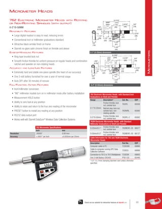


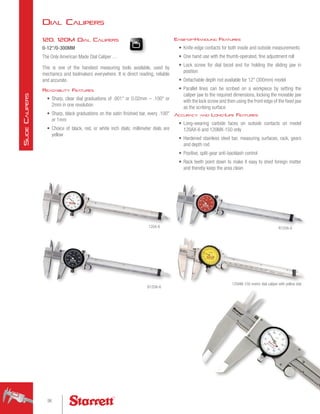


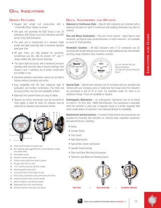
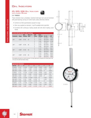
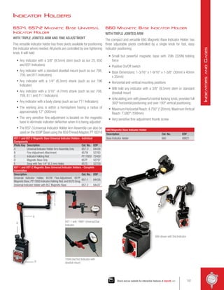
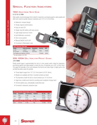
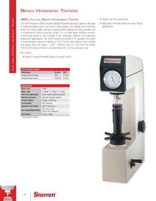
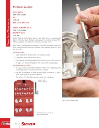
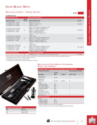
![252 Height Transfer Gages
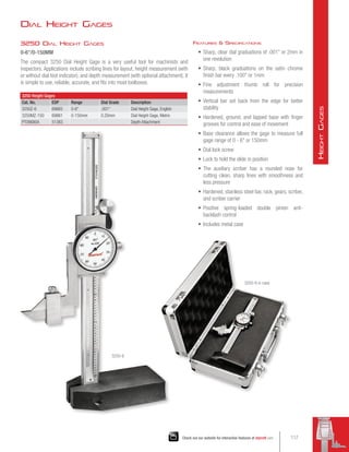
0-48/0-1200MM
The 252 Height Transfer Gage is ideal for use with test indicators or electronic
amplifiers to accurately transfer height settings from gage blocks, height gages
and other standards.
252 Height Transfer Gages
Range
Fine Adjustment
(Approximate)
Base Size
(Approximate)
Gage Rod
Dimension Cat. No. EDP
0-14
(350mm)
3/8 (9.5mm)
5-3/4 L x 3-1/2 W
(145mm x 90mm)
9 L x .375 Dia.
(225mm x 9.5mm)
with steps
252Z-14 55890
0-24
(600mm)
7-1/2 L x 4-1/2 W
(190mm x 115mm)
252Z-24 51216
0-48
(1200mm)
9 L x 6 W
(225mm x 150mm)
252Z-48 51217
Larger sizes available on special order.
Starrett 708, 709, 711, 650 Test Indicators; 25, 81, 196, 655, 656 Dial Indicators and supplementary
attachments also available.
Gage furnished with 9 (225mm) Rod and PT06784-A Gage Holding Rod in wood case.
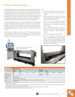
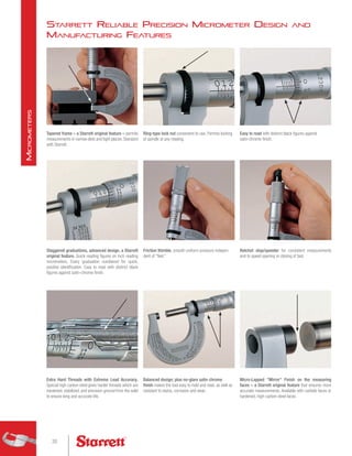
Accuracy and Long-Life Features
• Extreme rigidity provides the vibration-proof stability
necessary to permit precise repeat readings with
indicators of the highest amplification
• Extremely rigid, rectangular box-type hollow column
mounted integrally on a heavy base
• Adjusting mechanism is located in the base so the
column and indicator are isolated and not affected by
external factors, such as heat or hand pressure
Ease-of-Operation Features
• Hand-fitting base design for sure-grip handling and
easy movement
• Bottom of the base has three ground and lapped pads
for stability and smooth movement on the surface
plate
• Adjustable slide, incorporating a snug for holding test
indicators or electronic gage heads, has rapid vertical
manual adjustment
• Thumb screw allows slide to be locked
• Knob on base allows fine vertical adjustment of the
slide unit relative to the fixed column.This permits the
slide with its test indicator to be quickly and precisely
adjusted to the desired setting.
Tool and Gaging Holders
• A snug on the slide provides two holes (.375 [9.5mm]
and .156 [4mm]) for holding gage rods or scribers. A
9 (225mm) rod furnished with the gage is especially
useful for reaching confined areas or reaching heights
greater than the range of the gage.
• The rod has a major diameter of .375 (9.5mm) and
stepped diameters of 1/4 (3.2mm) and 7/32 (5.5mm)
at one end and 5/16 (8mm) at the opposite end
• 708 and 709 Test Indicators can be mounted on this
rod using PT22428 swivel clamp. 196 Universal Back-
Plunger Indicators can be mounted using Starrett snugs,
Part PT18718 or PT18724 (snugs not furnished).
• PT06784-A Gage Holding Rod is included to
accommodate the 715-1 Gaging Head when the
Transfer Gage is used with the 717 Electronic Gage.A
wire retaining clip keeps electronic gage head cables
from deflecting the gage-holding rod.
• 25, 81, 655 and 656 Dial Indicators also can be used
on the height gage by means of a PT06784-A Gage
Rod (furnished)
• Other useful attachments (extra) are surface gage
spindles (57C or 57D, 12 [300m]) and 18 [450mm])
– which are extremely useful for scribing and layout
Pictured with 717 Gage Amplifier and
715-12 lever probe.
Height Gage Accessories
121
Check out our website for interactive features at starrett.com
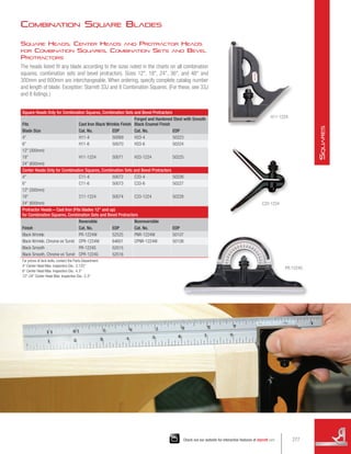
H
eight
G
ages](https://image.slidesharecdn.com/catalog33-precisiontoolcataloglo-res-220727130402-eab0982d/85/Catalog-33-Precision-Tool-Catalog-lo-res-pdf-121-320.jpg)


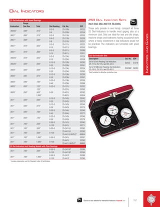


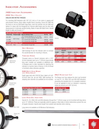


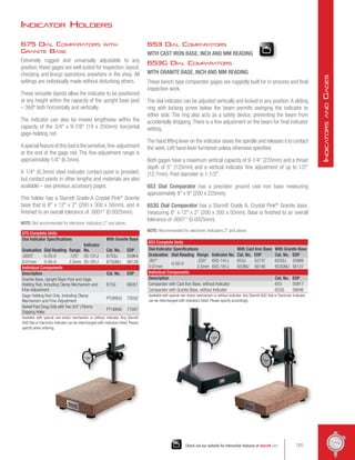


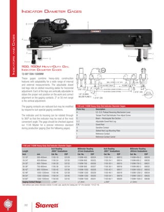


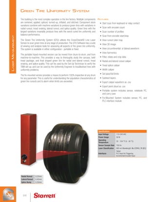
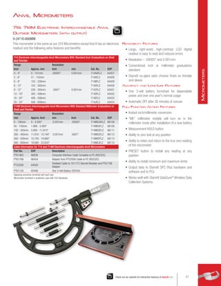
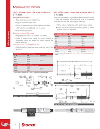
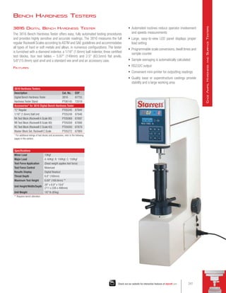
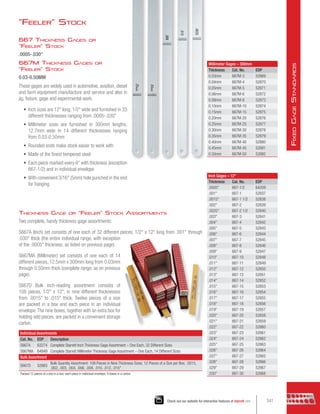
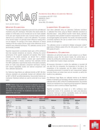
![781XT AccuBore®
Electronic
Bore Gages
See specifications on previous pages
781XT AccuBore Electronic Bore Gage Set – 2-Point Contact (.080-.250 [2-6 mm] Range)
Range
Number of Heads Number of Rings Cat. No. EDP
Inch mm
.080-.250 2-6 5 3 S781XTBZ 68169
781XT AccuBore Electronic Bore Gage Sets –
3-Point Contact (.250-8 [6-200mm] Range – Fixed Anvils)
.250-.375 6-10 2 1 S781XTCZ 68170
.250-.750 6-20 5 3 S781XTHZ 68658
.375-.750 10-20 3 2 S781XTDZ 68171
.750-2.00 20-50 3 3 S781XTEZ 67694
.750-4.00 20-100 6 4 S781XTJZ 67697
2.00-4.00 50-100 3 2 S781XTFZ 67695
4.00-6.00 100-150 2 1 S781XTKZ 67698
4.00-8.00 100-200 4 4 S781XTGZ 67696
6.00-8.00 150-200 2 1 S781XTLZ 67699
Accessories for 781XT AccuBore Electronic Bore Gages
Description Part No. EDP
Cable Link to 772 Data Collector, 761 Multiplexer PT61340 65648
Starrett Module #4 for 772 Data Collector, 761 Multiplexer PT61285 65647
Two 3-volt Batteries, No. CR2032 PT99492 65650
Larger sizes available on special order.
Gages are also available with dial indicators on special order.
Extensions for 781XT AccuBore Electronic Bore Gages
Cat. No. EDP
Ext. Size
Fits Models
Model Size
Inches mm Inches mm
78/782F 65484 2.5 63 78XT/780XT/781XT/782XT - 250-375mm 1/4-5/16 6-8
78/782G 65485 3 75 78XT/780XT/781XT/782XT - 375-500mm 3/8-1/2 10-12.5
78/782H 65486 4 100 78XT/780XT/781XT/782XT - 625-750mm 1/2-3/4 12.5-20
78/782J 65487 6 150 78XT/780XT/781XT/782XT - 1 thru 2 3/4-2 20-50
78/782K 65488 6 150 78XT/780XT/781XT/782XT - 2 thru 12 2-12 50-300
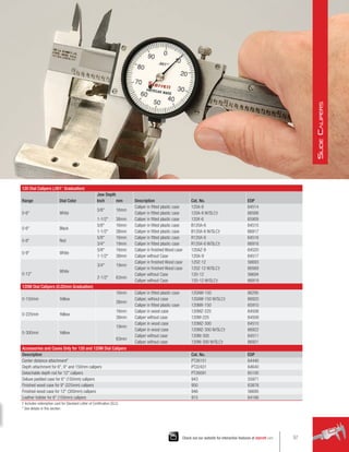
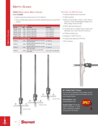
Extensions from 2-1/2 - 6 can be added to the 781XT,
enabling internal measurements in deep hole bores
S780XTKZ
Electronic Bore Gages
208
B
ore
G
ages](https://image.slidesharecdn.com/catalog33-precisiontoolcataloglo-res-220727130402-eab0982d/85/Catalog-33-Precision-Tool-Catalog-lo-res-pdf-208-320.jpg)

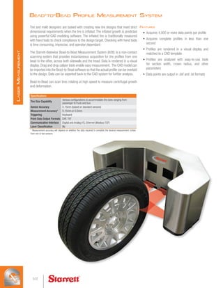
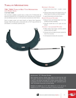
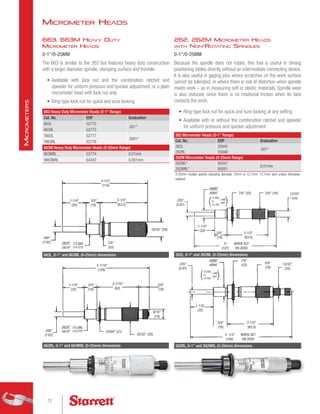
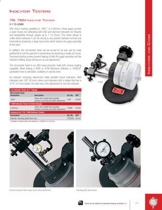
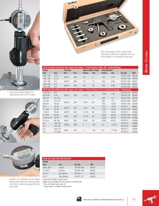
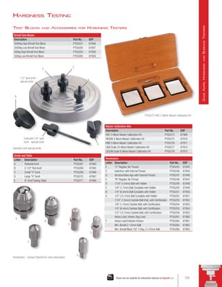
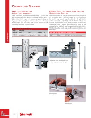
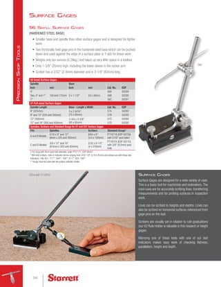
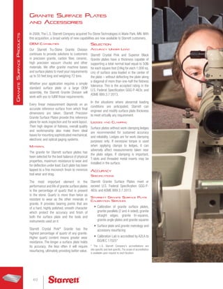
![Electronic Bore Gages
780XT Electronic Internal Micrometers with IP65
Protection (with output)
See specifications on previous page
780XT Electronic Internal Micrometer Sets, 2-Point Contact (.080-.250 [2-6mm] Range)
Range
No. of Heads No. of Rings Cat. No. EDP
Inch mm
.080-.250 2-6 S780XTBZ 12043
780XT Electronic Internal Micrometer Sets, 3-Point Contact (1/4-8 [6-200mm] Range), Fixed anvils
1/4-3/8 6-10 2 1 S780XTCZ 12044
3/8-3/4 10-20 3 2 S780XTDZ 12045
3/4-2 20-50 3 2 S780XTEZ 12046
2-4 50-100 3 2 S780XTFZ 12047
4-6 100-150 2 1 S780XTKZ 12049
4-8 100-200 4 2 S780XTGZ 12048
6-8 150-200 2 1 S780XTLZ 12050
Internal Extensions
Ext. Size
Fits Models
Model Size
Cat. No. EDP
Inch mm Inch mm
2.5 63 78XT/780XT/781XT–312-375 1/4-3/8 6-10 78/782F 65484
3 75 78XT/780XT/781XT–375-500 3/8-1/2 10-12.5 78/782G 65485
4 100 78XT/780XT/781XT–625-750 1/2-3/4 12.5-20 78/782H 65486
6 150 78XT/780XT/781XT–1 thru 2 3/4-2 20-50 78/782J 65487
6 150 78XT/780XT/781XT–2 thru 12 2-12 50-300 78/782K 65488
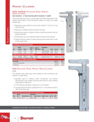
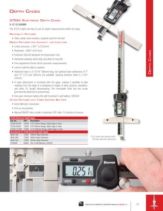
Internal Extensions for 78, 780, 781
Internal Micrometers
Extensions from 2-1/2 - 6 can be added to both the 780XT and 78XT, enabling internal
measurements in deep hole bores (Multiple extensions can also be used).
210
B
ore
G
ages](https://image.slidesharecdn.com/catalog33-precisiontoolcataloglo-res-220727130402-eab0982d/85/Catalog-33-Precision-Tool-Catalog-lo-res-pdf-210-320.jpg)

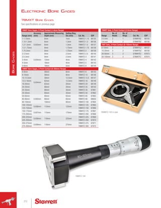


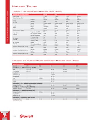


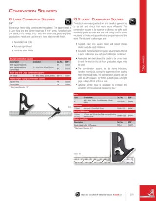


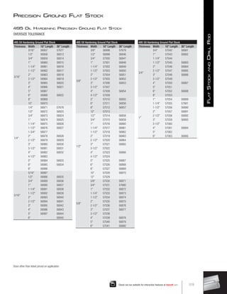
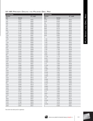
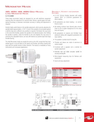
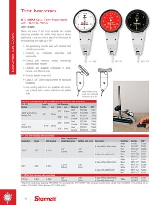
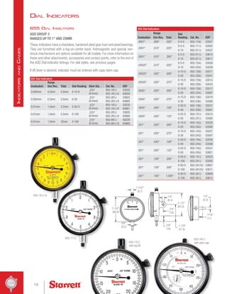
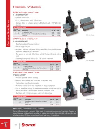
![Precision Rules
End Graduations
End graduations are useful for measuring depths, widths
of shoulders, recesses, grooves, etc. They are graduated in
32nds of an inch or millimeters on both ends of one side as
shown at the right.
Adjustable Steel Hook Rules
These improved Hook Rules feature an adjustable double
hook that can be shortened or extended on either side
in relation to any one of the four graduations on the rule.
This allows accurate measurements from shallow or deep
shoulders and also permits setting inside calipers to any of
the graduations. Hooks are hardened and may be adjusted
or removed by a slight turn of an eccentric stud.
Steel Hook Rules with Reversible Hook
These convenient Hook Rules permit accurate
measurements, even when the user cannot see if the rule
is aligned with the measuring edge.This is especially useful
for measuring from round corners, through hubs, for setting
inside calipers, etc. The single hook is hardened and may
be reversed or removed by a slight turn of an eccentric
stud.
Narrow Hook Rules with Reversible Hook
These useful Hook Rules are similar to the Hook Rules
described above, but have a narrow blade (only 3/16
[4.8mm] wide) which permits measurements through
holes as small as 7/32 (5.5mm) in diameter. Hooks are
hardened and may be reversed or removed by a partial turn
of the eccentric stud.
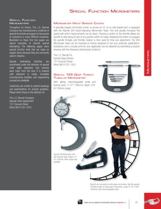
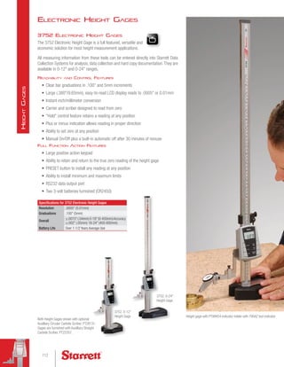
Steel Rule with Tapered End
This 6 rule, our C310T-6, is a favorite with all mechanics
because the tapered end permits measuring insides of
small holes, narrow slots, grooves, recesses, etc. The rule
has a taper from 1/2 width at the 2 graduation to 1/8
width at the end. Accurate, distinctive, photo-engraved
graduations in 32nds are on one side and 64ths on the
reverse side, with graduations always in a normal, easy-
to-read position. Made of tempered, full-flexible steel with
satin chrome finish.
Steel Rule with Pocket Clip
This handy 6 rule is designed for frequent use. It is made
of tempered, full-flexible steel and has accurate, photo-
engraved graduations in 32nds on one edge and 64ths on
the opposite edge, with satin chrome finish. C310K-6.
Useful Variation Features of Our Standard Precision Rules
289
Check out our website for interactive features at starrett.com
P
recision
R
ules
,
S
traight
E
dges
,
P
arallels](https://image.slidesharecdn.com/catalog33-precisiontoolcataloglo-res-220727130402-eab0982d/85/Catalog-33-Precision-Tool-Catalog-lo-res-pdf-289-320.jpg)


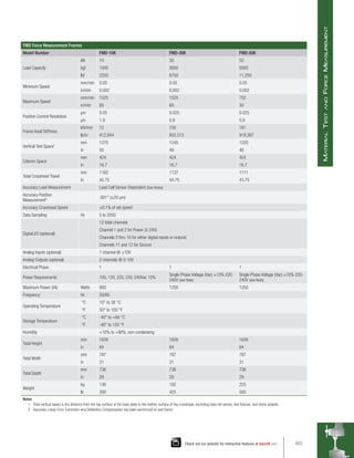
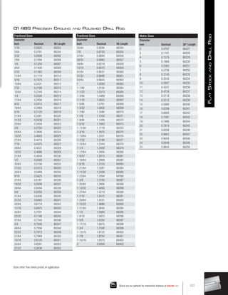
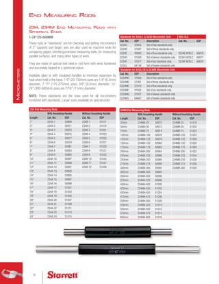
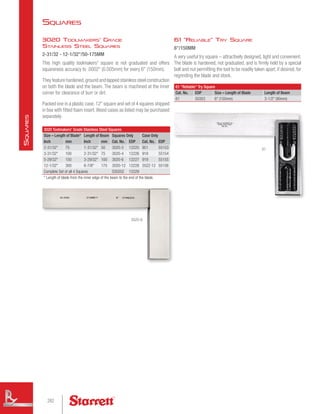
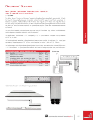
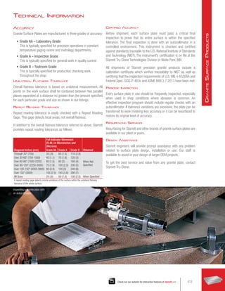
![Steel Beam Trammels
C251 Steel Beam Trammels
and Attachments
10-1/2 – 20/260 - 500MM BEAMS
A rigid, well-designed trammel for layout, scribing, and
measuring distances and circles. The top of the beam
is flattened so that when the trams are clamped in
position, they will not turn from pressure on the points.
The trams are held in place by spring friction, which
prevents them from sliding when the nuts are loosened
for setting. One tram has a fine-adjusting screw for the
points.
Each tram has a knurled swivel grip at the top that
turns freely, making it very convenient to swing the tool
when scribing circles. The 3 (75mm) points may be
adjusted for length in the spring chucks and can be
easily replaced with caliper legs or other attachments
listed. The ball points with 3 (75mm) holder permit
working from holes up to 1-1/2 (38mm) in diameter.A
pair of 3 (75mm) caliper points is included with each
trammel.
• Ideal for draftsmen, engineers, metal-workers for
layout work, scribing and measuring
• Furnished with rigid steel beam – 10-1/2
(263mm), 14-1/2 (360mm) or 20 (500mm)
sizes
• Bright chrome finish for longer life, resistance to
corrosion
• Highly versatile – handy attachments available to
extend range and measure
C251A
J
H
D
E
C251 Steel Beam Trammels
Max. Dividing Range Max. Circle Scribing Diameter Range Beam Size
Cat. No. EDP
Inch mm Inch mm Inch mm
9 225mm 18 450mm 10-1/2 263mm C251A 51205
13-1/2 338mm 26 650mm 14-1/2 363mm C251B 51207
18 450mm 36 900mm 20 500mm C251C 51209
C251 Trammel Individual Attachments Only
Description Photo Key Cat. No. EDP
Coupling, with Extra 20 (600mm) Beam (When used with C251C will scribe circle 72 [1800mm] diameter) D C251D 51211
Ball Points and Holder E C251E 51212
Steel Point and Socket (One) (Has .076 [1.9mm] hole diameter to hold leads) H C251H 51214
Needle Point (Chrome not available) (One) J 251J 51203
320
C
alipers
,
D
ividers
and
T
rammels](https://image.slidesharecdn.com/catalog33-precisiontoolcataloglo-res-220727130402-eab0982d/85/Catalog-33-Precision-Tool-Catalog-lo-res-pdf-320-320.jpg)


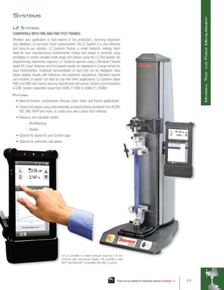
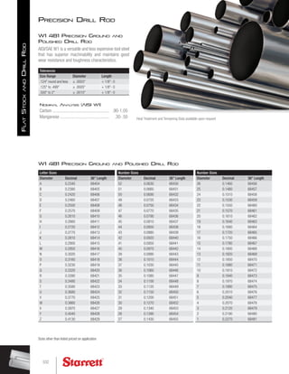
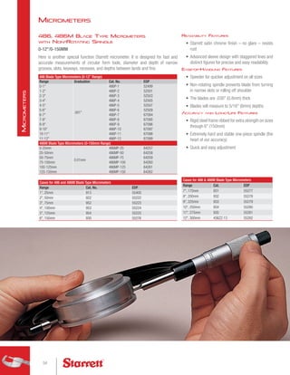
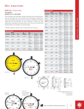
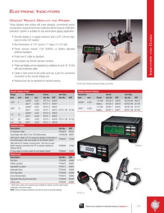
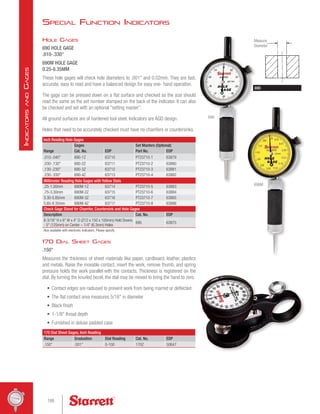
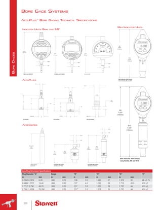
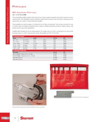
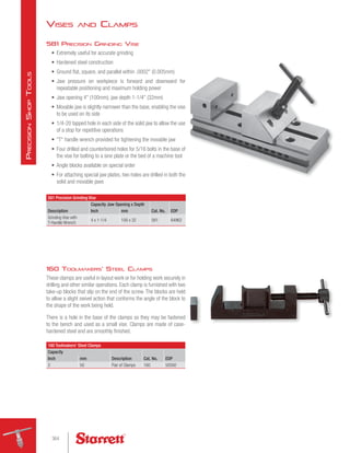
![568 V-Blocks and Clamps for Round or Square Work
2/50MM ROUND CAPACITY
1-7/16/36MM SQUARE CAPACITY
These rugged and versatile blocks have the following features:
• Hardened steel, precision ground parallel and square
• V-grooves are ground central and parallel to the sides and base – perfect alignment in
matched pairs
• Clamps have screw holes at 45º and 90º to hold either square or round work
• Stepped groove construction permits
high or low clamp mounting for small or
large work
• Clamps do not project over the width of
the block, permitting it to be used on the
base, ends or sides
• 3/8-16 tapped holes permit mounting
blocks on faceplates or angle irons
• Each block is 2-1/2 long x 3 wide x 2
high (63 x 75 x 50mm)
Precision V-Blocks
566 Dual-Vee Magnetic V-Block
1-3/4/44MM CAPACITY
• Designed for versatility and accuracy
• All working surfaces are precision ground
• Two precision vees will hold round stock sizes from
1/4 - 1-3/4 (6.4-44mm) diameter
• Powerful, permanent magnet is controlled by a rotary
switch
• All working surfaces are heat treated for long wear
and stability
• Each block is 2-1/2 wide x 3 high x 3 long (63 x
75 x 75mm)
566 Dual-Vee Magnetic V-Block
Capacity
Description Cat. No. EDP
Inch mm
1-3/4 44 Dual-Vee Magnetic V-Block 566 63323
568 V-Blocks and Clamps
2 (50mm) Dia. Round;
1-7/16 (36mm) Square
(1-9/16 [40mm] with Screw at Top)
1 V-Block and Clamp 568A 52590
Complete Set with 2 V-Blocks and 2 Clamps (Matched
Pair)
568C 52592
Clamp Only 568B 52591
2.97
(85.4)
2.53
(64.3)
Pair of 568 V-Blocks
1.5
(38.1)
1.98
(50.3)
566
361
Check out our website for interactive features at starrett.com
P
recision
S
hop
T
ools](https://image.slidesharecdn.com/catalog33-precisiontoolcataloglo-res-220727130402-eab0982d/85/Catalog-33-Precision-Tool-Catalog-lo-res-pdf-361-320.jpg)


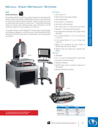


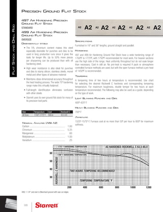
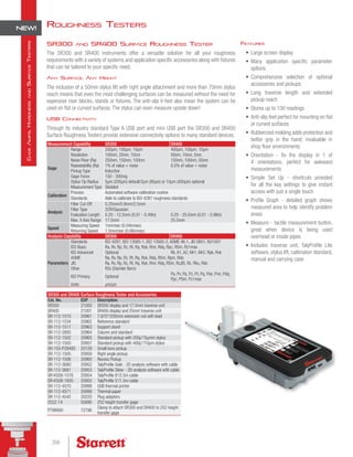
![Features
• X-Y travel for AVR200: 8 x 4 (200 x 100 mm)
• X-Y travel for AVR300: 12 x 8 (300 x 200 mm)
• Z travel: 8 (200 mm) with 2.0x auxiliary lens
• Full CNC X-Y-Z positioning or motorized manual
positioning using a pendant with joystick and
trackball
• Windows®
7 Professional operating system for
network connectivity
• MetLogix M3 CNC metrology software
• Video edge detection (VED)
• Field-of-view (FOV) measurements integrated
with stage motion
• Renishaw scales for .00002 (0.1µm) of X,Y and
Z axis
• Accuracy: 2.5µm + 5L/1000 for X and Y, 3.5µm
+ 5L/1000 for Z
• Color digital video camera
• Collimated LED sub-stage illumination
• Ring Light LED surface illumination
• Granite base
• AVR200 H x W x D: 34 x 20.5 x 27 (863 x 520
x 685mm)
• AVR300 H x W x D: 34 x 29.2x 35 (865 x 740
x 890mm)
Options
• Dedicated 6.5:1 or 12:1 CNC zoom optics
• Quick-change bayonet lens mount for telecentric
optics
• Bayonet mountable 0.30x, 0.50x, 0.80x, 1.0x,
2.0x, 4.0x telecentric optics
• 0.5x, 1.5x and 2.0x auxiliary lenses for zoom
optics
• Quadrant LED surface illumination for zoom optics
• DXF/FOV option pack for automatic comparison to
CAD designs
• Modular system workstation
• Calibration standards
Weight and Dimensions
AVR200 AVR300
Net Weight
200lbs 250lbs
90kg 113kg
Shipping Weight
250lbs 300lbs
115kg 135kg
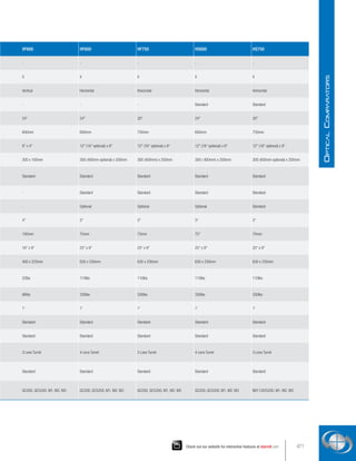
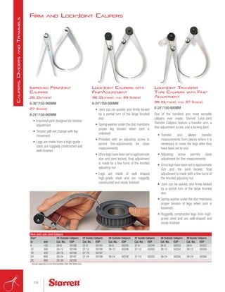
Automatic Vision Metrology Systems
AVR
AVR200 AND AVR300
The AVR CNC automatic vision metrology systems are ideal for repetitive
measurements and automatic comparison to CAD files. They are available with
dedicated zoom optics or a quick-change bayonet lens mount which accepts a
choice of telecentric lenses for micron-level resolution and optical distortion down to
0.001% for accurate field-of-view (FOV) measurements. These can encompass an
entire small part up to 2.00 x 1.50 or a feature of a larger part and be seamlessly
integrated with stage motion to measure parts with a length up to 8 (AVR200) or
12 (AVR300).
AVR hardware features a granite base for maximum stability, recirculating ball
linear guides for smooth and precise stage motion, and full CNC control for high
throughput. The AVR line is built around a 21 all-in-one touch screen PC which
runs MetLogix M3-CNC software under Windows®
7. M3 software capabilities
include 3-axis measurements and 2D geometrical constructs (points, lines, angles,
rectangles).
AVR200
[ 487 ]
Ø19.2
[ 520 ]
20.5
[ 872 ]
34.3
[ 682 ]
26.9
[ 235 ]
9.3
[ 193 ]
7.6
[ 495 ]
Ø19.5
AV300
[ 673 ]
26.49
[ 617 ]
Ø24.30
[ 228 ]
8.98
[ 200 ]
7.88
[ 846 ]
33.31
[ 698 ]
Ø27.49
[ 872 ]
34.34
For more information please see the Options and
Specifications table at the end of this section.
432
V
ision
S
ystems
NEW!](https://image.slidesharecdn.com/catalog33-precisiontoolcataloglo-res-220727130402-eab0982d/85/Catalog-33-Precision-Tool-Catalog-lo-res-pdf-432-320.jpg)


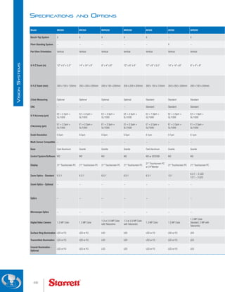


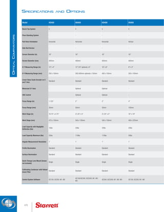
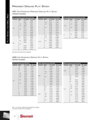
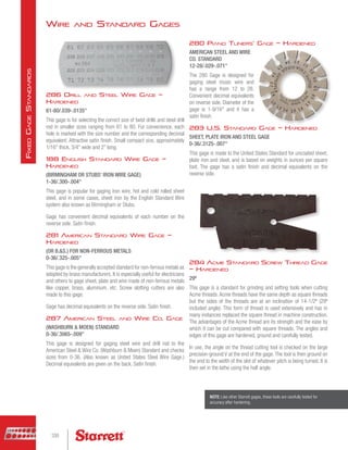
![Side Bed Optical Comparators
HS600
The HS600 floor-standing horizontal optical comparator has all the
same features as the HF600, except it has the screen position set
to the side of the workstage area allowing close, comfortable and
unrestricted access to the viewing and control area. It has a 12
(300mm) X-axis (16 [400mm] optional) and 8 (200mm) Y-Axis
motorized travel (CNC control optional), Q-axis digital protractor with
angular measurements to 1' resolution, and your choice of powerful
Quadra-Chek®
or MetLogix™
software control systems.A time tested,
cost-effective solution for non-contact measurement.They are simple
to use, yet have excellent capacity and performance to satisfy an
exceptionally wide range of dimensional inspection applications and
complex measuring requirements. At the heart of these systems are
precision optics, superb lighting, and a highly accurate workstage that
combine to ensure bright, sharp images and exceptional accuracy.
Features and Specifications
• Accommodates components up to 330lbs (150kg)
• 24 (600mm) diameter screen
• 4 lens capacity
• Canopy and curtains standard
• Automatic edge detection option
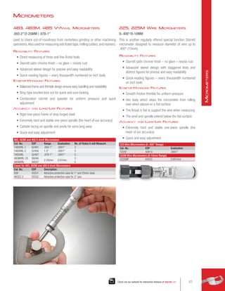
• 20 (500mm) extended workstage available
HS750
The HS750 floor-standing horizontal optical comparator has all the
same features as the HF750, except it has the screen position set
to the side of the workstage area allowing close, comfortable and
unrestricted access to the viewing and control area. It has an extra
large 30 (762mm) screen, 12 (300mm) X-axis (16 [400mm]
optional) and 8 (200mm) Y-Axis motorized travel (CNC control
optional), lens turret with 3 lens capacity, Q-axis digital protractor
with angular measurements to 1' resolution, powerful Quadra-Chek®
or MetLogix™
software control systems, canopy and curtains. A time
tested, cost-effective solution for non-contact measurement.They are
simple to use, yet have excellent capacity and performance to satisfy
an exceptionally wide range of dimensional inspection applications
and complex measuring requirements. At the heart of these systems
are precision optics, superb lighting and a highly accurate workstage
that combine to ensure bright,sharp images and exceptional accuracy.
Features and Specifications
• Very rigid and inherently stable metal construction ensures
optimum performance and accuracy
• Large diameter screens provide extensive field of view giving the
user more component detail on the screen
• Side screen design gives the operator uninterrupted access to
the screen and working area
• Large workstage, power driven on both axes, with high load
capacity
• CNC workstage option
• 20 (500mm) extended travel workstage available
• Available with the full range of Quadra-Chek®
or
MetLogix™
readout systems
• Canopy and curtains standard
• Wide range of ancilliaries and options allows specification
tailoring and easy upgrading
• Accessories include alternative workstage, precision centers,
vees, vices etc.
For more information please see the Options and
Specifications table at the end of this section.
466
O
ptical
C
omparators](https://image.slidesharecdn.com/catalog33-precisiontoolcataloglo-res-220727130402-eab0982d/85/Catalog-33-Precision-Tool-Catalog-lo-res-pdf-466-320.jpg)