Downloaded 341 times


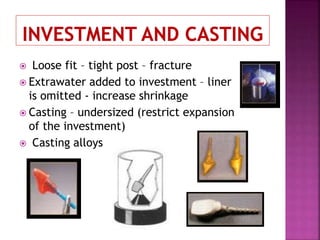
![ Luting agents - fill the dead space in root canal
Voids lateral canal PDL inflammation
Lentulo spirals used to load cement in post space
Post core inserted gently to avoid hydrostatic pressure
[root fracture]
Groove given in parallel sided post [excess cement
escapes]](https://image.slidesharecdn.com/castpost-190129172147/85/Cast-post-Restoration-of-endodontically-treated-teeth-81-320.jpg)


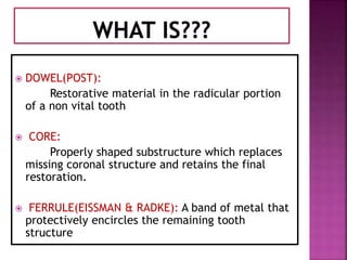
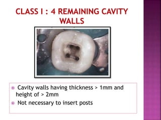
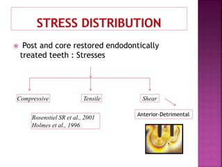
This document provides information on restoring endodontically treated teeth using post and core systems. It discusses the history of post systems, definitions, reasons for restoration, types of post and core systems, principles of tooth preparation, and the procedure for post and core fabrication. Custom cast and prefabricated post options are presented, as well as factors to consider for post length, width, and retention form. The importance of ferrule effect for fracture resistance is emphasized. In summary, this document serves as a guide for restoring endodontically treated teeth using post and core systems in a way that maximizes strength, retention and minimizes further damage to tooth structure.


