Downloaded 63 times


![United States Patent [191
Karbo
[11 1 3,738,348
[45] June 12, 1973
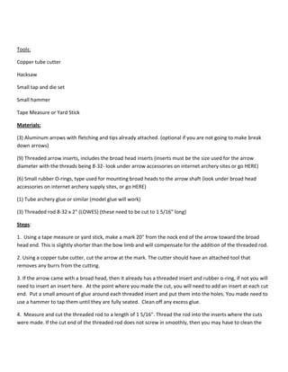
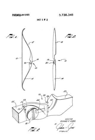
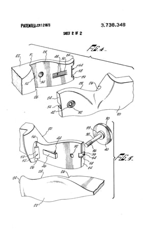
[54] TAKE-DOWN ARCHERY BOW
[75] Inventor: Richard S. Karbo, Whittier, Calif.
[73] Assignee: Brunswick Corporation, Chicago, Ill.
[22] Filed: Feb. 11, 9171
[21] Appl. No.: 114,567
[52] U.S. Cl. ............................ .. 124/24, 273/DIG. 7
[51] Int. Cl. ............................................ .. F41b 5/00
[58] Field of Search ................ .. 124/24, 23, 22, 25,
124/41, 35
[56] References Cited
UNITED STATES PATENTS
3,527,196 9/l970 Karbo l . . . . . . . l . . . . . . . . . . . . . . .. 124/20
2,163,503 6/1939 Tate . . . . . . . . . . . . . . . . . . . . . .. 124/23
2,642,661 6/1953 Fredrickson . . . . . . . . . .. 124/23
3,262,442 7/1966 Grable ................................ .. 124/24
Primary Examiner-Richard C. Pinkham
Assistant Examiner-William R. Browne
Att0rney—D0nald S. Olexa, Sheldon L. Epstein.
John G. Heimovics et al..
[ 57] ABSTRACT
A take-down archery bow having a pair of bow limbs
with stepped interior ends which are adapted to be
locked in the mated position by a threaded bolt. The
lateral surfaces between the steps has an interengaging
ramp and incline combination which interacts to apply
a longitudinal force on the bow limbs to draw the
stepped ends of the bow limbs together as the bolt
draws the lateral surfaces together. A pair of interen
gaging boss and cut-out portions are also provided to
absorb a portion of the bending loads acting on the
limbs.
4 Claims, 5 Drawing Figures](https://image.slidesharecdn.com/breakdownbow-141119052732-conversion-gate01/85/Break-down-bow-10-320.jpg)
![as1}- . ,
‘a
United States Patent [191
Hoyt, Jr. I i -
[111 3,814,075
[451 June 4,1974
[54]
[76]
[22]
[21]
[52]
[51]
[58]
l [561
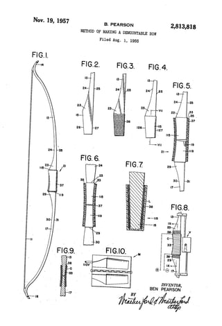
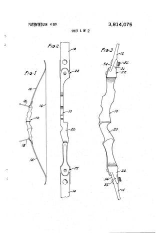
TAKE DOWN ARCHERY BOW WITH A
MOUNT FOR A BOW STABILIZING
ELEMENT '
lnventor: Earl H. Hoyt, Jr., 1 l5 10 Natural
2,642,66l
3.265.055
3,326,200
3,527.196
Bridge Rd., Bridgeton, Mo. 65617
Filed: July 21, 1972
Appl. No.: 274,095
US. Cl. ........................... .. 124/24 R, 124/30 R
Int. Cl. ............................................ .. F4lb 5/00
Field of Search ..... 124/23 R, 24 R, 25, 22,
124/35, 41
References Cited
UNlTED STATES PATENTS
(3/1953 . Fredrickson .................... 124/23 R
8/l966 Gage ...........
6/l96'7 Grublc .......... ..
9/1970 Karl'm ............................. .. l24/24R
Priniary Examiner—Richard C. Pinkham
Assistant Examiner—William R. Browne
Attorney, Agent, or Firm—Charles E. Markham
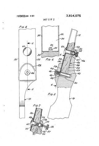
[57] ABSTRACT
An archery bow with limbs detachably connected to a
handle section. The butt end portions of the limbs are
freely entered in close fitting relationship between lon
gitudinally spaced forward and rear wall portions of
sockets formed in the ends of- the handle section. A
?xed pin extending fore and aft across the bottom of
each socket engages a groove in the end of the limb
and a short stud projecting from the rear side of each
limb parallel with the ?xed pin and spaced from the
end of the limb enters a hole in the rear socket wall in
close ?tting relationship to position and hold the limbs
, in lateral alignment. A thumb screw extends through
the rear wall of each socket and is threadedly engaged
in the short projecting studs to clamp the limbs to the
rear socket walls. The forward socket walls are shorter
than the rear walls and a portion of each rear socket
wall near the bottom is relieved to permit entry of the
limbs in a slightly forward tilted position thereby to
permit free entry of the limbs between the socket wall
portions and to permit entry of the short projecting
studs. .'
9 Claims, 7 Drawing Figures](https://image.slidesharecdn.com/breakdownbow-141119052732-conversion-gate01/85/Break-down-bow-13-320.jpg)
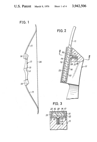
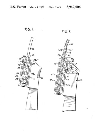
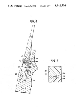
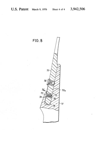
!['United States Patent [191 [111 3,942,506
lzuta [45] Mar. 9, 1976
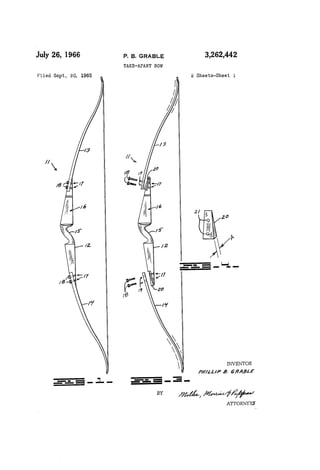
[54] DEMOUNTABLE ARCHERY BOW 3,814,075 6/1974 Hoyt ............................... .. 124/24 R
[75] Inventor: Tadao lzuta, Hamamatsu, Japan
[73] Assignee: Nippon Gakki Seizo Kabushiki
Kaisha, l-lamamatsu, Japan
[22] Filed: June 20, 1974
[21] Appl. No.: 481,403
[52] US. Cl. ........ .1 .... .-. ........... .. 124/24 R; 124/30 R
[51] Int. Cl.2 ............................ ..- ............ .. F4-1B 5/00
[58] Field of Search ...... .. 124/23 R, 24 R, 30 R, 25,
124/22, 30 A, 52; 279/79, 85
[56] References Cited
UNITED STATES PATENTS
2,476,762 7/1949 Petre et a1. ..................... .. 279/79 X
~ 2,522,388 9/1950 Madsen . . . . . . . . . . . . . . . . .. 279/79 X
2,562,462 7/1951 Jackson . . . . . . . . . . . . . . . . . . . .. 124/52
2,580,930 1/1952 Kost .................................... .. 279/79
2,958,552 11/1960 Vosbikian et al ............... .. 279/79 X
2,972,493 2/1961 Waters ............................ .. 279/79 X
3,415,240 12/1968 Bear . . . . . . . . . . . . . . . . .. 124/23 R
3,628,519 12/1971 l-lofmeister .................. .. 124/24 R
3,695,248 10/1972 lzuta ............................... .. 124/24 R
Prim-my Examiner-Anton O. Oechsle
Assistant Examiner-William R. Browne
Attorney, Agent, or Firm-Haseltine, Lake_& Waters
[57] ABSTRACT
A demountable archery bow with a handle provided at
the opposite ends thereof with limb receiving means,
and limbs to be removably inserted in the respective
limb receiving means. A click stop mechanism is pro
vided between each limb receiving means and the as
sociated limb to facilitate the assembly and disassem
bly of the handle and limbs. The click stop mechanism
may have a recess formed on the limb side in a man
ner to open in a direction perpendicular to that in
which the limb is inserted in the limb receiving means,
and a spring biased ball provided on the handle side,
the ball being received in the recess under the spring
biasing force when the limb is inserted in the handle
and the ball being forcedly removable from the recess
when a force pulling the limb away from the handle is
exerted on the limb.
4 Claims, 8 Drawing Figures
T 724](https://image.slidesharecdn.com/breakdownbow-141119052732-conversion-gate01/85/Break-down-bow-16-320.jpg)
![United States Patent [191
Killian
[11] 4,187,826
[45] Feb. 12, 1980
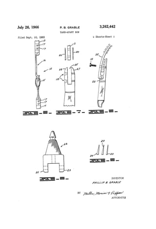
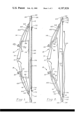
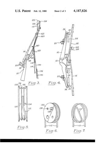
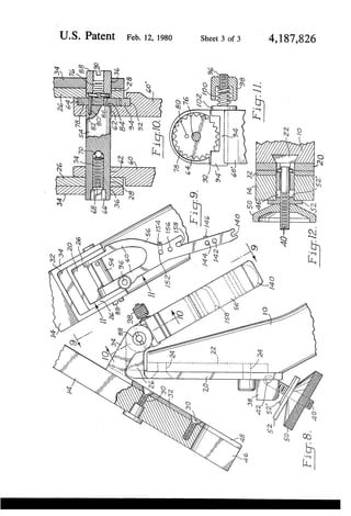
[54] FOLDING LIMB COMPOUND ARCHERY
BOW
[76] Inventor: Gerald I. Killian, 16016 SE. 82nd Dr.,
Clackamas, Oreg. 97015
[21] Appl. No.: 787,860
[22] Filed: Apr. 15, 1977
[51] Int. Cl.2 . . . . . . . . . . . . . . . . . . .. F41B 5/00
[52] US. Cl. .................................. .. 124/24 R; 29/235;
124/88
[58] Field of Search ................ .. 124/23 R, 24 R, 90,
124/88, 86; 403/12; 24/1226, 135 N, 135 R;
29/235
[56] References Cited
U.S. PATENT DOCUMENTS
3,207,145 9/ 1965 Browning et al. ............... .. 124/23 R
3,253,587 ' 5/ 1966 Pearson .................... .. 124/23 R
3,294,078 12/ 1966 Allen .... .. 124/23 R
3,352,296 11/1967 Burger .. .... .. 124/23 R
3,486,495 12/ 1969 Allen 124/ 24 R
3,841,295 10/1974 Hunter .. .. 124/24 R
3,957,027 5/1976 Drake .... .. 124/23 R
4,050,137 9/ 1977 Carlson ................................ .. 29/235
FOREIGN PATENT DOCUMENTS
708863 7/ 1941 Fed. Rep. of Germany ........ .. 24/ 122.6
Primary Examiner—Richard C. Pinkham
Assistant Examiner—William R. Browne
Attorney, Agent, or Firm—James E. Nilles
[57] ABSTRACT
A compound archery bow has resilient limbs pivotally
attached to the opposite ends of a central handle by
hinges allowing the limbs to be folded between an oper
ative position and a folded position. The limbs are re
leasably secured in an operation position by a latch
mechanism. A secondary cable interconnects each limb
and a tensioning lever on the handle for adjustably
pre-tensioning the limbs. A ratchet shaft assembly piv
otally mounts the tensioning levers and allows the ten
sion of each limb to be adjusted. The limbs can be re
laxed by lengthening a stringer, whereupon the latch
mechanism can be opened, allowing the limbs to be
released and pivoted on the hinges to their folded posi
tion adjacent the belly side of the bow. Cam members
are mounted at the outer end of each limb and around
which the end segments of the bow string are wrapped
at least about 270° in each direction. Thus the cam mem
bers can be reversibly rotated to accommodate either
tensioning of the bow for projecting an arrow, or relax
ing of the bow for release of the limbs. As a result the
bow may be folded and unfolded without altering its
pre-established tension characteristics.
9 Claims, 12 Drawing Figures](https://image.slidesharecdn.com/breakdownbow-141119052732-conversion-gate01/85/Break-down-bow-21-320.jpg)
![United States Patent [19]
Izuta
4,574,766
Mar. 11, 1986
[11] Patent Number:
[45] Date of Patent:
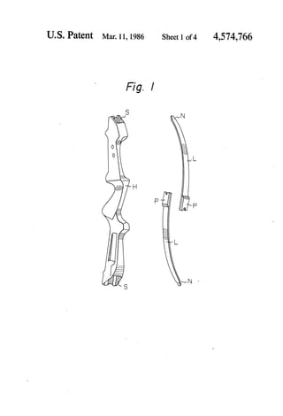
[54] JOINT STRUCTURE OF A TAKE-DOWN
TYPE ARCHERY BOWS
[75] Inventor:
[73] Assignee:
Tadao Izuta, Hamamatsu, Japan
Nippon Gakki Seizo Kabushiki
Kaisha, Japan
[21] Appl. N0.: 404,291
[22] Filed: Aug. 2, 1982
[30] Foreign Application Priority Data
Aug. 6, 1981 [JP] Japan ......................... .. 56-117220[U]
[51] Int. Cl.4 .............................................. .. F41B 5/00
[52] US. Cl. ................................ .. 124/23 R; 124/88
[58] Field of Search .......... .. 124/23 R, 24 R, DIG. 1,
‘ 124/88, 86
[56] References Cited
U.S. PATENT DOCUMENTS
261,610 7/1882 Howe .............................. .. 124/23 R
3,262,442 7/1966 Grable 124/24 R
3,415,240 12/1968 Bear ..... .. 124/23 R
3,757,762 9/1973 Cousin 124/24 R
3,766,904 10/1973 Izuta .................... .. 124/24R
3,874,360 4/1975 Armstrong et a]. 124/23 R
3,921,598 11/1975 Helmick .......................... .. 124/24R
3,957,027 5/1976 Drake ............................. .. 124/23R
FOREIGN PATENT DOCUMENTS
114300 lO/l978 Japan .............................. .. 124/23 R
Primary Examiner—Richard J. Apley
Assistant Examiner—William R. Browne
Attorney, Agent, or Firm—Lerner, David, Littenberg,
Krumholz & Mentlik
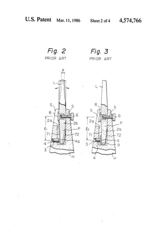
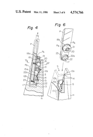
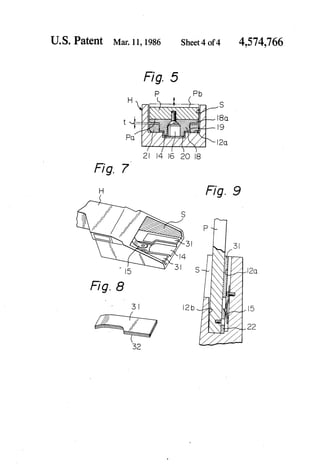
[57] ABSTRACT
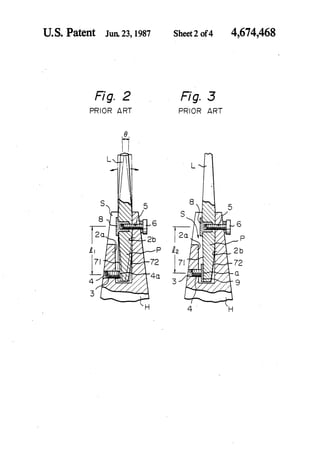
A joint structure between each limb and a handle riser
of a take-down type archery bow is described employ
ing a plug-socket engagement based upon a two posi
tion support. The ?rst position support is located near
the mouth of a handle riser socket and enables the
change in angular position of the limbs with respect to
the handle riser by the replacement of a pair of flat
spacers of predetermined thickness. The second posi
tion support, being unaffected by the ?rst position sup
port, is located near the bottom of the socket for releas
ably engaging the plug end of the limbs in order to
prevent accidental removal of the limbs from the handle
riser socket.
4 Claims, 9 Drawing Figures](https://image.slidesharecdn.com/breakdownbow-141119052732-conversion-gate01/85/Break-down-bow-25-320.jpg)
![United States Patent [19]
Izuta
[54] JOINT STRUCTURE OF A TAKE-DOWN
TYPE ARCHERY BOW
[75] Inventor:
[73] Assignee:
Tadao Izuta, Hamamatsu, Japan
Nippon Gakki Seizo Kabushiki
Kaisha, Japan
[21] Appl.No.: 801,001
[22] Filed: Nov. 22, 1985
Related US. Application Data
[62] Division of Ser. No. 404,291, Aug. 2, 1982, Pat. No.
4,574,766.
[30] Foreign Application Priority Data
Aug. 6, 1981 [JP] Japan ......................... .. 56-ll7220[U]
[51] Int. Cl.4 ............... .. F41B 5/00
[52] US. Cl. ............................... .. 124/23 R; 124/ 88
[58] Field of Search .......... .. 124/23 R, 24 R, DIG. l,
124/88
[56] References Cited
U.S. PATENT DOCUMENTS
3,874,360 4/1975 Armstrong et a1. ............. .. 124/23 R
1
i
[11] Patent Number: 4,674,468
[45] Date of Patent: Jun. 23, 1987
3,921,598 11/1975 Helmick .......................... .. 124/24R
3,942,506 3/1976 Izuta ............................... .4 124/24R
Primary Examiner—Richard C. Pinkham
Assistant Examiner—Benjamin Layno
Attorney, Agent, or Firm—Lerner, David, Littenberg,
Krumholz & Mentlik
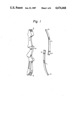
[57] ABSTRACT
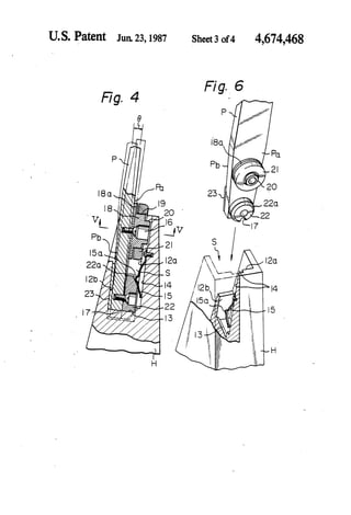
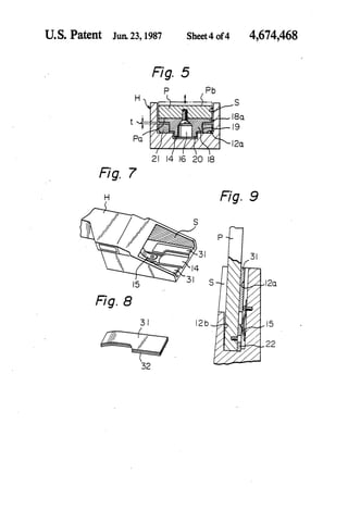
In a joint structure between each limb and a handle riser
of a knock-down type archery bow employing a plug
socket engagement, a two position support is formed by
a pair of separate supporter pieces ?xed to the face side
of the socket, one supporter piece located closer to the
socket mouth forming the ?rst support for enabling
change in angular position of the limb with respect to
the handle riser, and the other supporter piece located
closer to the socket bottom forming the second support
unmoved by any change in the ?rst support. The ab
sence of holes in the socket walls assures a strong con
struction without the increase in weight, and the adjust
ment by the ?rst support causes no disturbance on the
originally designed balance of force over the entire
construction.
3 Claims, 9 Drawing Figures](https://image.slidesharecdn.com/breakdownbow-141119052732-conversion-gate01/85/Break-down-bow-30-320.jpg)
![IllllllllllllllllIllllIlllllllllllllllllllIllllIlllllllllllllllllllllllllll
US005172679A
United States Patent [19] [11] Patent Number: 5,172,679
Mussack [45] Date of Patent: Dec. 22, 1992
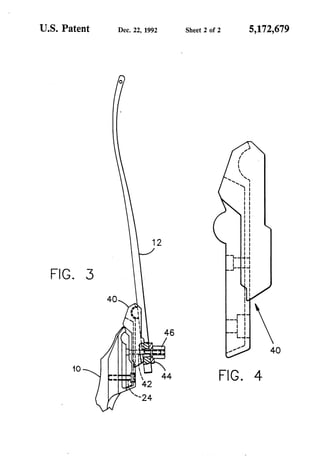
[54] MODULAR CONSTRUCTION FOR [56] References Cited
COMPOUND ARCHERY BOW us. PATENT DOCUMENTS
75 I t l - ' - - 3,821,946 7/1974 [ ] nven or geggn R Mussack, Clifton Springs, 3184x195 10/1974
' ' 3,942,506 3/1976
. 4,064,862 12/1977
[73] Asstgnee: Golden Eagle Archery, Inc., 4,261,320 4/1981
Farmington, NY. 4,574,766 3/1986
. Primary Examiner—Peter M. Cuomo
[211 App]' No" 749’312 Attorney, Agent, or Fz'rm—Hoffrnan Stone
[22] Filed: Aug. 23, 1991 [57] ABSTRACT
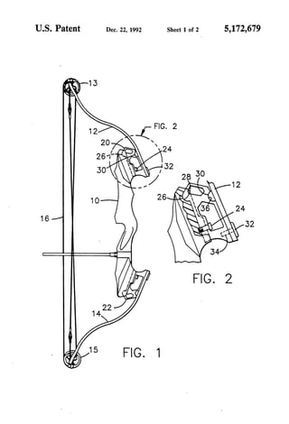
A modular construction for compound archery bows
R l d U s A l, _ includes sets of spacer blocks for insertion between the
6 ate ' ' pp ‘canon Data bow handle and the limbs. The blocks are shaped to
[63] Continuation-impart of Ser. No. 569,868, Aug. 20, provide selected variations in the geometry of the bows,
1990, abandoned. selectively adjusting the brace height and the overall
length of the bow. The manufacturer is enabled to cre
[51] Int. Cl.5 .............................................. .. F41B 5/00 ate bOWs of many different characteristics without in
[52] U.S. Cl. ................................ .. 124/25.6; 124/23.1; vesting in dies to produce differently shaped handles,
124/88 needing only differently shaped spacer blocks.
[58] Field of Search ..................... .. 124/88, 25.6, 23.1, ‘
124/ 24.1, 86 3 Claims, 2 Drawing Sheets
14
22](https://image.slidesharecdn.com/breakdownbow-141119052732-conversion-gate01/85/Break-down-bow-35-320.jpg)
![llllllllllllllllllllllll|||llllllllllfllllllllllllllllllllllllllllllllllllll US005 6923A
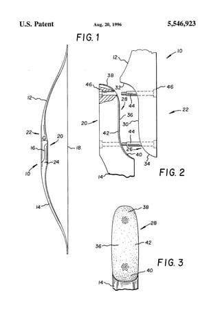
Unlted States Patent [19] [11] Patent Number: 5 546 923 9 9
Duncan [45] Date of Patent: Aug. 20, 1996
[54] TAKE-DOWN ARCHERY BOW 3,942,506 3/1976 Izuta .
3,957,027 5/1976 Drake ...................................... .. 124/88
[76] Inventor: Douglas J. Duncan, 8157 Budworth 4,091,790 5/1973 Hoyt, Jr- -
School Rd., PO. Box 742, Beetown, ill‘?
' , , zu a .
WIS‘ 53802 4,693,230 9/1987 Sugouchi ................................ .. 124/88
4,793,319 12/1988 Vaughan et a1..
[21] Appl. No.: 330,831 5,025,774 6/1991 Martin ..................................... .. 124/89
. 5,280,779 1/1994 Smith 124/88
[22] F1169: , Oct- 27’ 1994 5,291,874 3/1994 Harrison .............................. ..-. 124/23.1
6
------------------------------------------------------ .
[52] US. Cl. . . . . . . . . . . . . . . . . . . . . . . . .. 124/23.1
[58] Field of Search ................................ .. 124/23.1, 24.1, Traditional BOW/hunter, NO- 76695, Aug/5994 1993, PP
124/25.6, 86, 88; 403/393 4647
[56] References Cited Primary Examiner—-Eric K. Nicholson
Assistant Examiner—-J0hn A. Ricci
U.S. PATENT DOCUMENTS Attorney, Agent, or Firm-Arrnstrong, Westerman, Hatton',
261,610 7/1882 Howe. McLeland 8‘ Naughton
1,709,630 4/ 1929 Rounsevelle ......................... .. 124/231
2,125,591 8/1938 Smith. [57] ABSTRACT
gelm .................................. .. 124/23.1 An archery bow having a belly and a back and comprising
, , owar . - 2,813,818 11/1957 Pearson ............................ .. 1241231 X two elopgated branch .cqmponems each having a.“ and’ the
3 156 230 1m964 Groves ends being detachably JOlIlCd together at a]o1ntw1th at least
3,527,196 9/1970 Kal'bO ................. . . 124/241 one releasable fastener- The joint is de?ned by mating
3:612:028 10/1971 Karbo _ """"""" ' ' ' surfaces on the ends of each component and is between the
3,733,343 6/1973 Karbo _ belly and the back of the bow. The mating surfaces of each
3,766,904 10/1973 Izuta . component have a ?rst curved surface extending to the bow
3,771,508 11/1973 Black et a1. . belly and a second curved surface extending to the bow
3,814,075 6/1974 Hoyt, Jr. . back.
3,821,946 7/1974 Griggs.
3,874,360 4/1975 Annstrong et a1. .
3,921,598 11/1975 Helmick . 18 Claims, 1 Drawing Sheet
22](https://image.slidesharecdn.com/breakdownbow-141119052732-conversion-gate01/85/Break-down-bow-38-320.jpg)
![United States Patent [19]
Cox et al.
US006019097A
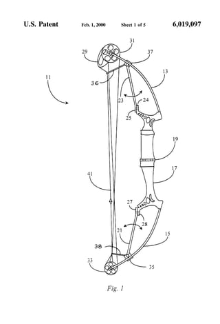
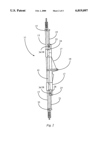
6,019,097
Feb. 1, 2000
[11] Patent Number:
[45] Date of Patent:
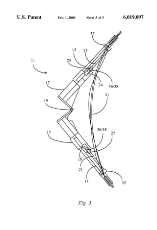
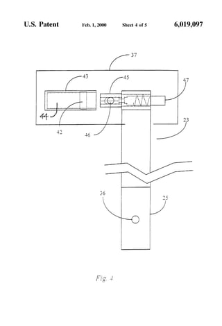
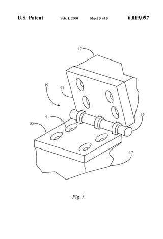
[54] DE-TENSIONING AND BREAKDOWN
SYSTEM FOR A COMPOUND BOW
[76] Inventors: Jimmie D. Cox, 18701 Vierra Canyon
Rd., Salinas, Calif. 93907; Douglas T.
Bresette, 45 Rialto Dr., Watsonville,
Calif. 95076
[21] Appl. N0.: 09/096,859
[22] Filed: Jun. 12, 1998
[51] Int. Cl.7 .. .............. .. F41B 5/00
[52] US. Cl. ................ .. . 124/23.1; 124/25.6
[58] Field of Search ............................ .. 124/1, 23.1, 25.6,
124/86, 88
[56] References Cited
U.S. PATENT DOCUMENTS
2,228,823 1/1941 Helm .................................... .. 124/231
2,514,638 7/1950 Grenier 124/231
3,156,230 11/1964 Groves . . . . . . . . . . . . . . . . . . .. 124/231
4,291,452 9/1981 Whitman et a1. .. 124/231 X
4,599,987 7/1986 ReZmer . . . . . . . . . . . . . . . . . .. 124/231
5,125,389 6/1992 Paff . . . . . . . . . . . .. 124/86
5,746,192 5/1998 Gissel ........................................ .. 124/1
Primary Examiner—John A. Ricci
ll
Attorney, Agent, or Firm—Milton Wolson
[57] ABSTRACT
A foldable archery bow has a center section and tWo ?exible
arms extending in substantially opposite directions, describ
ing a boW plane, and a separation interface disposed in the
center section and positioned to alloW the boW to be sepa
rated into to separate sections. At least one latching connec
tor is attached to a ?rst point on one of the ?exible arms, and
is adapted, When the ?exible arm to Which it is attached is
substantially ?exed, to latch at a second point on the same
side of the separation interface as the ?rst point. By drawing
the boW, Which ?exes the ?exible arms, and latching the
latching connector, all tension is released from the boW
string or strings, and all forces thereby removed from the
separation interface. The separation interface, normally fas
tened in a closed position, may then be unfastened and
separated, alloWing the boW to divide into the tWo separate
sections forming a smaller package than in the assembled
aspect. The boW may be again set up by aligning and
refastening the separation interface, drawing the boW, and
unlatching the connector, restoring the same tension to the
how that it had before folding. In some embodiments a hinge
is employed at the separation interface, alloWing the boW to
fold, and a variety of force removal mechanisms are taught.
12 Claims, 5 Drawing Sheets](https://image.slidesharecdn.com/breakdownbow-141119052732-conversion-gate01/85/Break-down-bow-40-320.jpg)

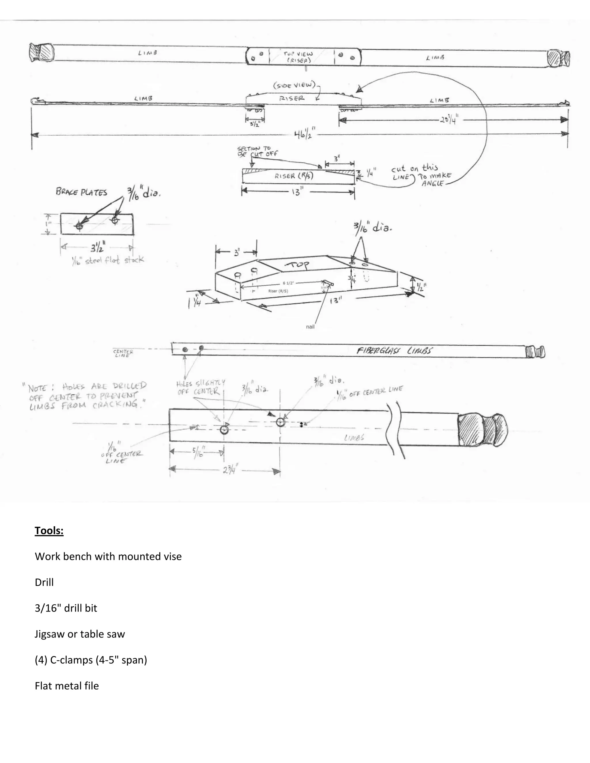
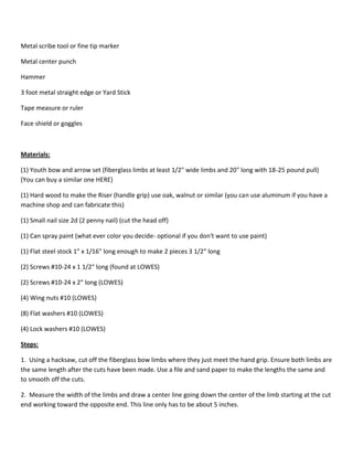
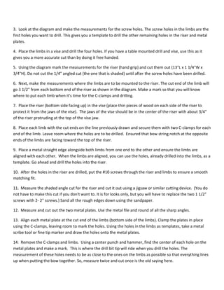
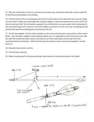
This document provides instructions for making a takedown recurve bow. It lists the necessary tools and materials, which include a youth bow kit, wood, metal plates and screws. It then provides 18 steps to assemble the bow, including cutting the limbs to length, drilling holes to attach the limbs to the wooden riser grip, and adding metal plates and screws to connect the limbs securely while allowing them to be detached. The final steps include stringing the bow and making a carrying case.