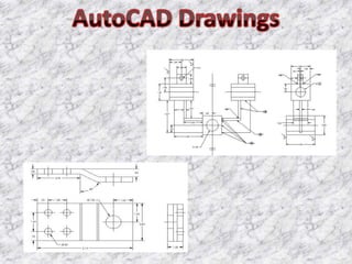
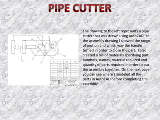
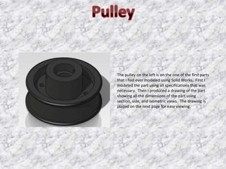
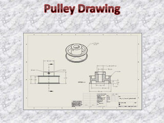
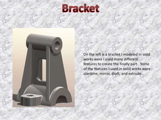
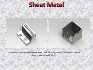
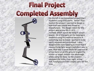
The parallel clamps is the first assembly
drawing that I had ever completed. First
I had to draw all the individual parts.
Then I modeled all rearranged the parts
to show where they went and how far
apart that the clamp would open.
Finally, I completed a bill of materials
showing quantity of parts
needed, material specifications and the
name of each part.
The connector in the picture to the left
was redesigned to be made into a cast
part and then machined down to its
finally specifications. The drawing
includes specifications on finishes and
hole sizes.
The drawing to the left represents a pipe
cutter that was drawn using AutoCAD. In
the assembly drawing I showed the range
of motion and which way the handle
turned in order to close the part. I also
created a bill of materials specifying part
numbers, names, material required and
quantity of parts required in order to put
the assembly together. On the next page
you can see where I modeled all the
parts in AutoCAD before completing the
assembly.
The pulley on the left is on the one of the first parts
that I had ever modeled using Solid Works. First I
modeled the part using all specifications that was
necessary. Then I produced a drawing of the part
showing all the dimensions of the part using
section, side, and isometric views. The drawing is
placed on the next page for easy viewing.
On the left is a bracket I modeled in solid
works were I used many different
features to create the finally part. Some
of the features I used in solid works were
combine, mirror, draft, and extrude.
These two sheet metal objects were created using every feature possible for
                       sheet metal in Solid Works.
On the left is my completed project that I
modeled using solid works. When I first
started the project I wanted to design a
bow that was simple and cheap to
manufacture. The design intent for the
project was to use the K.I.S.S.
method, which stands for keep it simple
stupid. All of the parts on the bow were
modeled using this method because if
something was to break I wanted it to be
easily repaired and assembled. I also
designed this bow keeping in mind that it
needed to be light weight and short axle to
axle, that way it could easily be used out of
a tree stand or on the ground to give the
hunter or target shooter the advantage
when using the bow. In this project I
modeled the limbs, riser, sight, arrow
rest, hand grip and two simple cams for the
bow.
This is the sketch I drew on graph paper
when I first started the project. I made a
rough sketch of a bow and made it kind
of look like I wanted it to in the end.
Throughout the semester I made
changes to the design in order to fit the
design intent of the project.
This is the sight I modeled for my project.
I made everything very simple on it and
made it easily adjustable. Along with
that I decided to stay away from fiber
optic sights because they have a
tendency of breaking if jarred around to
much. I made three slots in it that way
the person using the bow would be able
to mount an aftermarket light on it for
low light situations in any place that they
desired. Finally I made the sight capable
of mounting a quiver on it for carrying
arrows.
On the right is the arrow rest that I
modeled to fit my final project. I decided
to make it a drop away arrow rest. This
type of rest allows no friction when
shooting the bow, therefore allowing
maximum accuracy and speed. The rest
is easily adjustable and fits the criteria of
the project very well.

Porfolio Power Point

  • 3.
    The parallel clampsis the first assembly drawing that I had ever completed. First I had to draw all the individual parts. Then I modeled all rearranged the parts to show where they went and how far apart that the clamp would open. Finally, I completed a bill of materials showing quantity of parts needed, material specifications and the name of each part.
  • 5.
    The connector inthe picture to the left was redesigned to be made into a cast part and then machined down to its finally specifications. The drawing includes specifications on finishes and hole sizes.
  • 6.
    The drawing tothe left represents a pipe cutter that was drawn using AutoCAD. In the assembly drawing I showed the range of motion and which way the handle turned in order to close the part. I also created a bill of materials specifying part numbers, names, material required and quantity of parts required in order to put the assembly together. On the next page you can see where I modeled all the parts in AutoCAD before completing the assembly.
  • 9.
    The pulley onthe left is on the one of the first parts that I had ever modeled using Solid Works. First I modeled the part using all specifications that was necessary. Then I produced a drawing of the part showing all the dimensions of the part using section, side, and isometric views. The drawing is placed on the next page for easy viewing.
  • 11.
    On the leftis a bracket I modeled in solid works were I used many different features to create the finally part. Some of the features I used in solid works were combine, mirror, draft, and extrude.
  • 12.
    These two sheetmetal objects were created using every feature possible for sheet metal in Solid Works.
  • 13.
    On the leftis my completed project that I modeled using solid works. When I first started the project I wanted to design a bow that was simple and cheap to manufacture. The design intent for the project was to use the K.I.S.S. method, which stands for keep it simple stupid. All of the parts on the bow were modeled using this method because if something was to break I wanted it to be easily repaired and assembled. I also designed this bow keeping in mind that it needed to be light weight and short axle to axle, that way it could easily be used out of a tree stand or on the ground to give the hunter or target shooter the advantage when using the bow. In this project I modeled the limbs, riser, sight, arrow rest, hand grip and two simple cams for the bow.
  • 14.
    This is thesketch I drew on graph paper when I first started the project. I made a rough sketch of a bow and made it kind of look like I wanted it to in the end. Throughout the semester I made changes to the design in order to fit the design intent of the project.
  • 15.
    This is thesight I modeled for my project. I made everything very simple on it and made it easily adjustable. Along with that I decided to stay away from fiber optic sights because they have a tendency of breaking if jarred around to much. I made three slots in it that way the person using the bow would be able to mount an aftermarket light on it for low light situations in any place that they desired. Finally I made the sight capable of mounting a quiver on it for carrying arrows.
  • 16.
    On the rightis the arrow rest that I modeled to fit my final project. I decided to make it a drop away arrow rest. This type of rest allows no friction when shooting the bow, therefore allowing maximum accuracy and speed. The rest is easily adjustable and fits the criteria of the project very well.