Download to read offline
![28
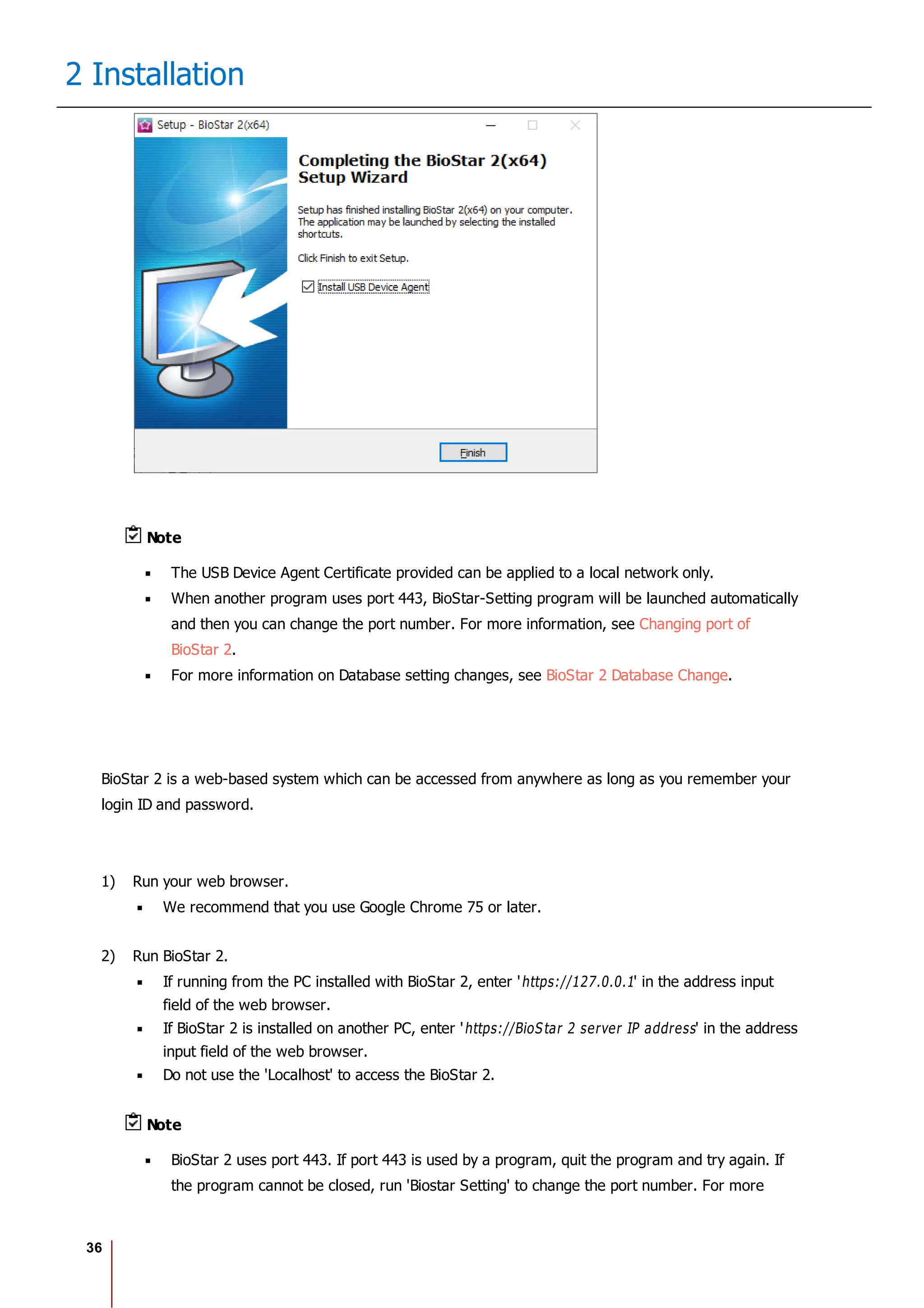
2 Installation
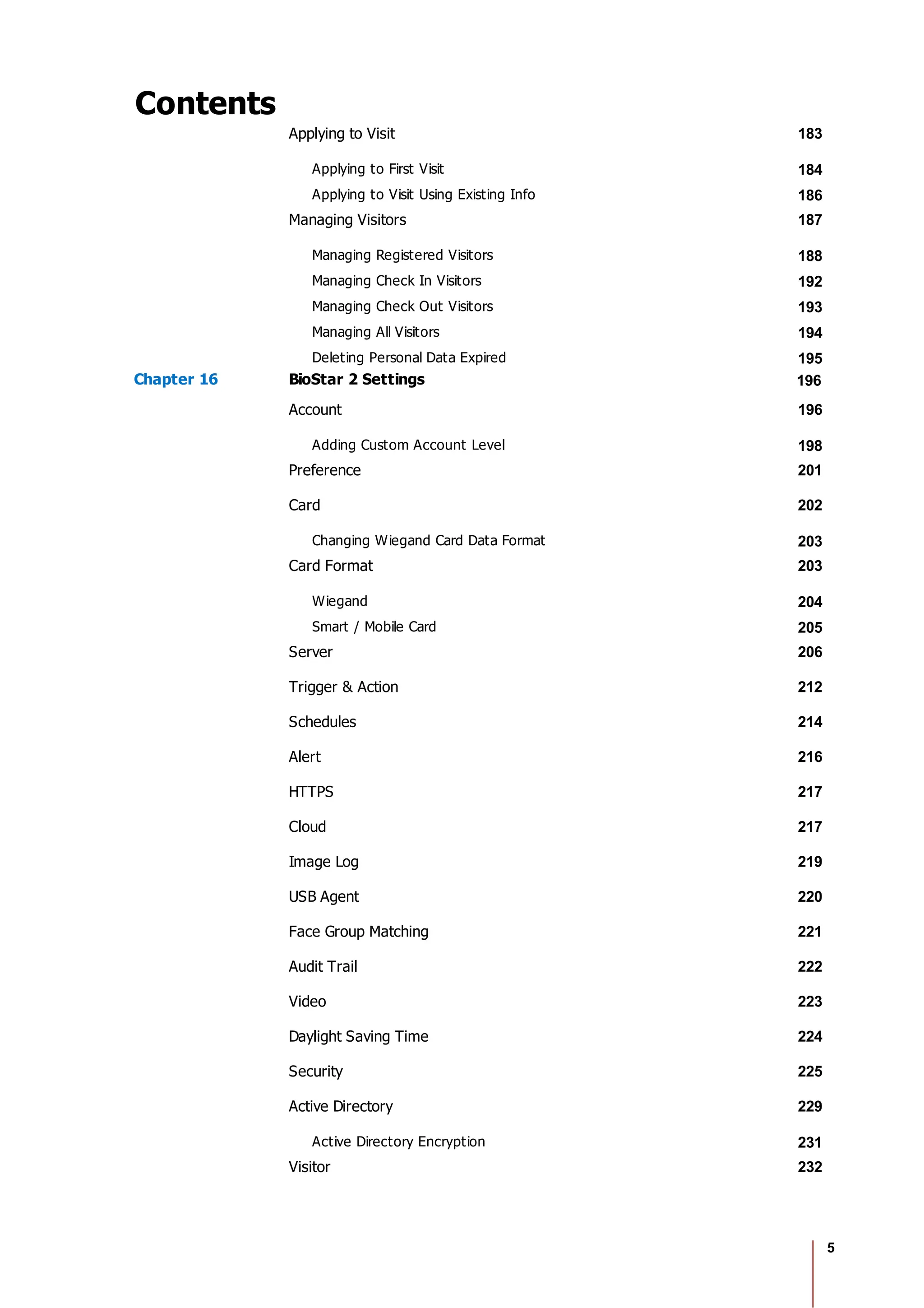
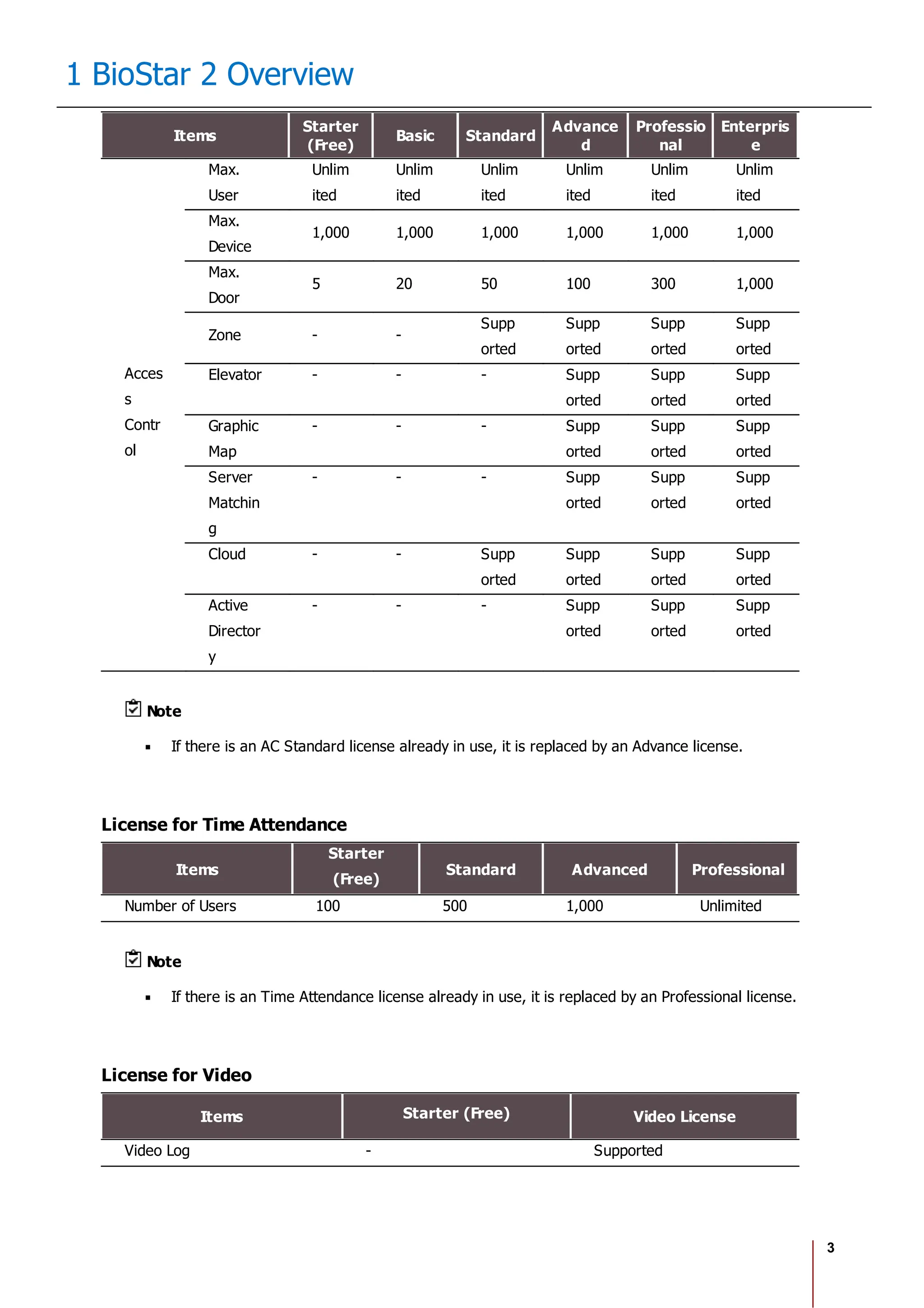
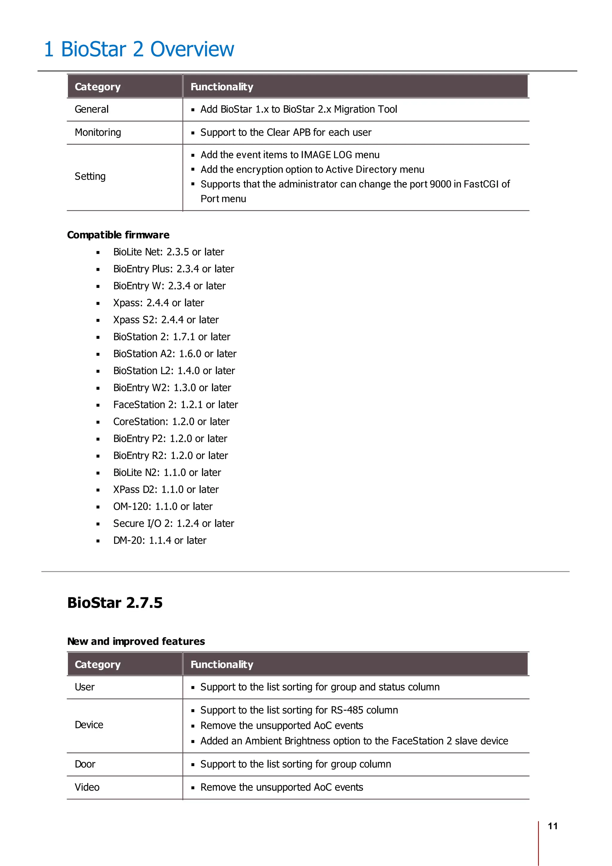
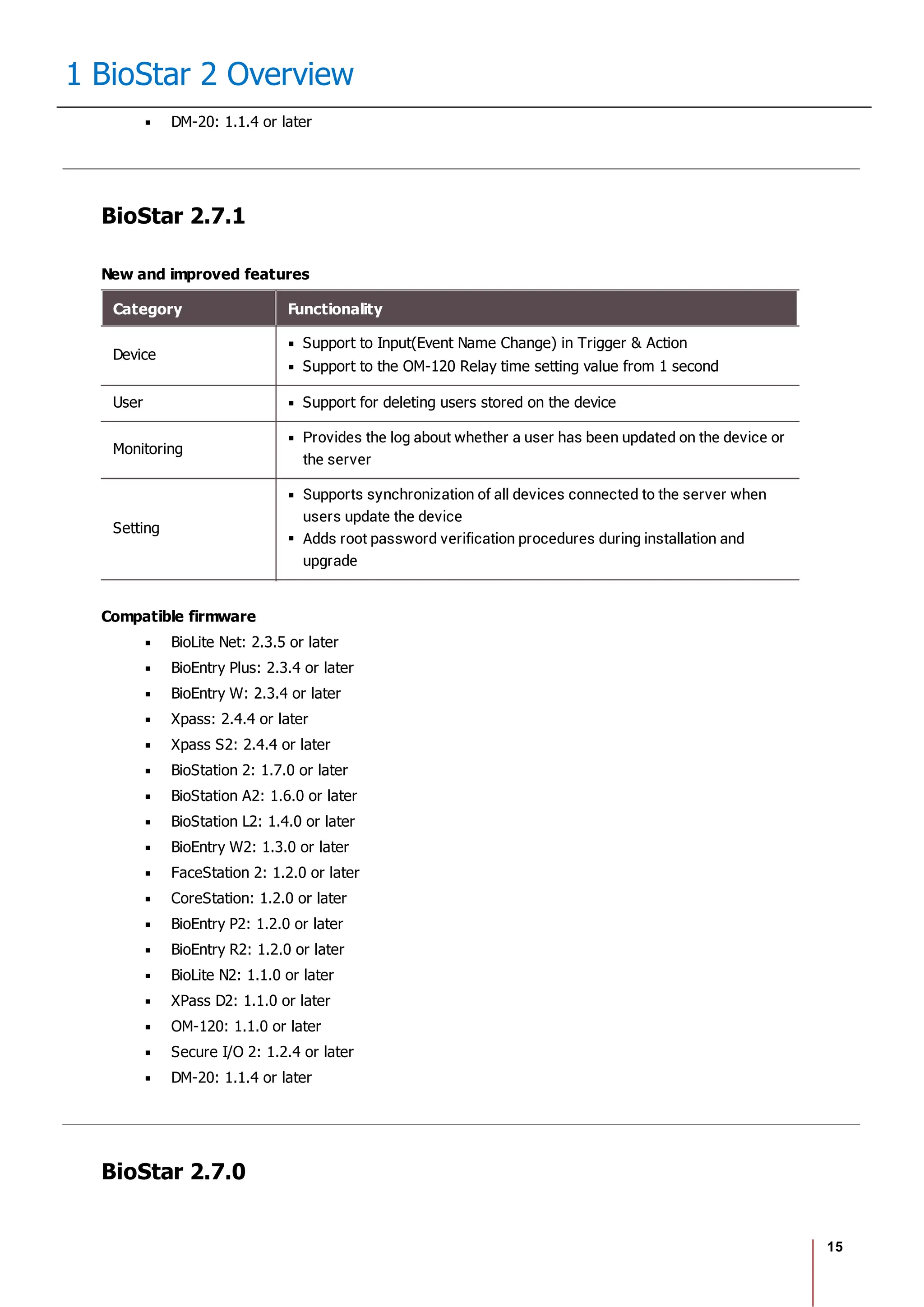
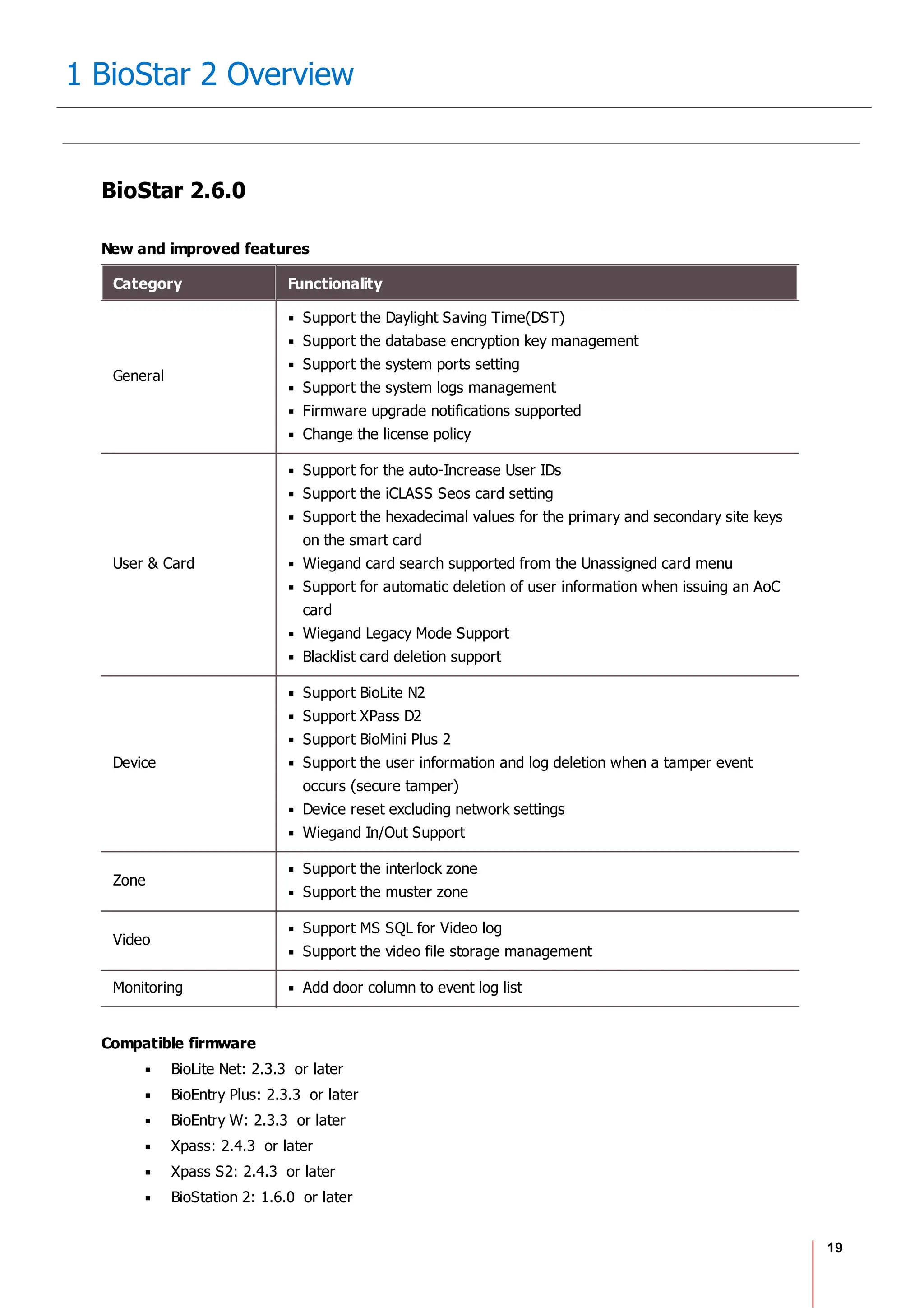
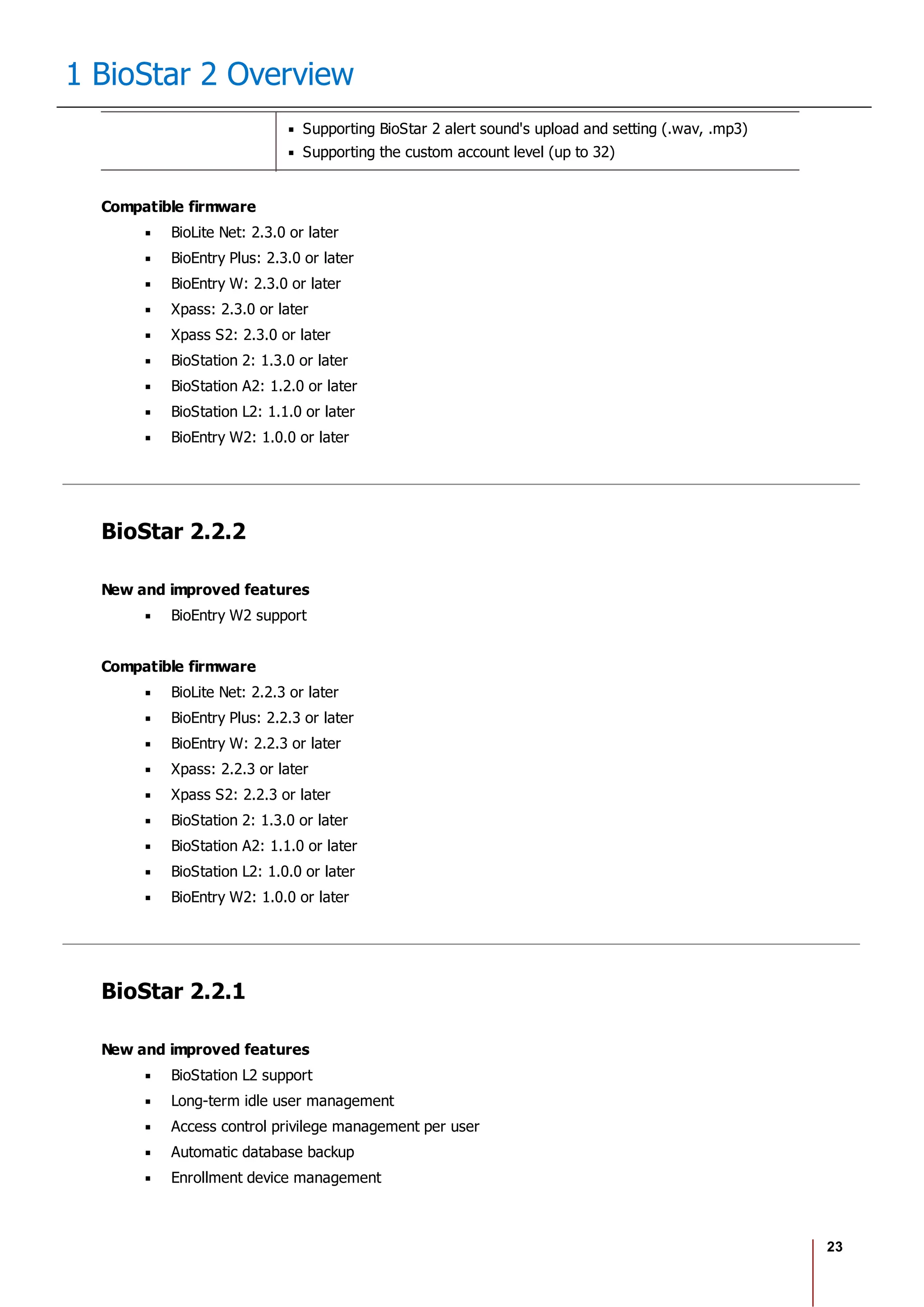
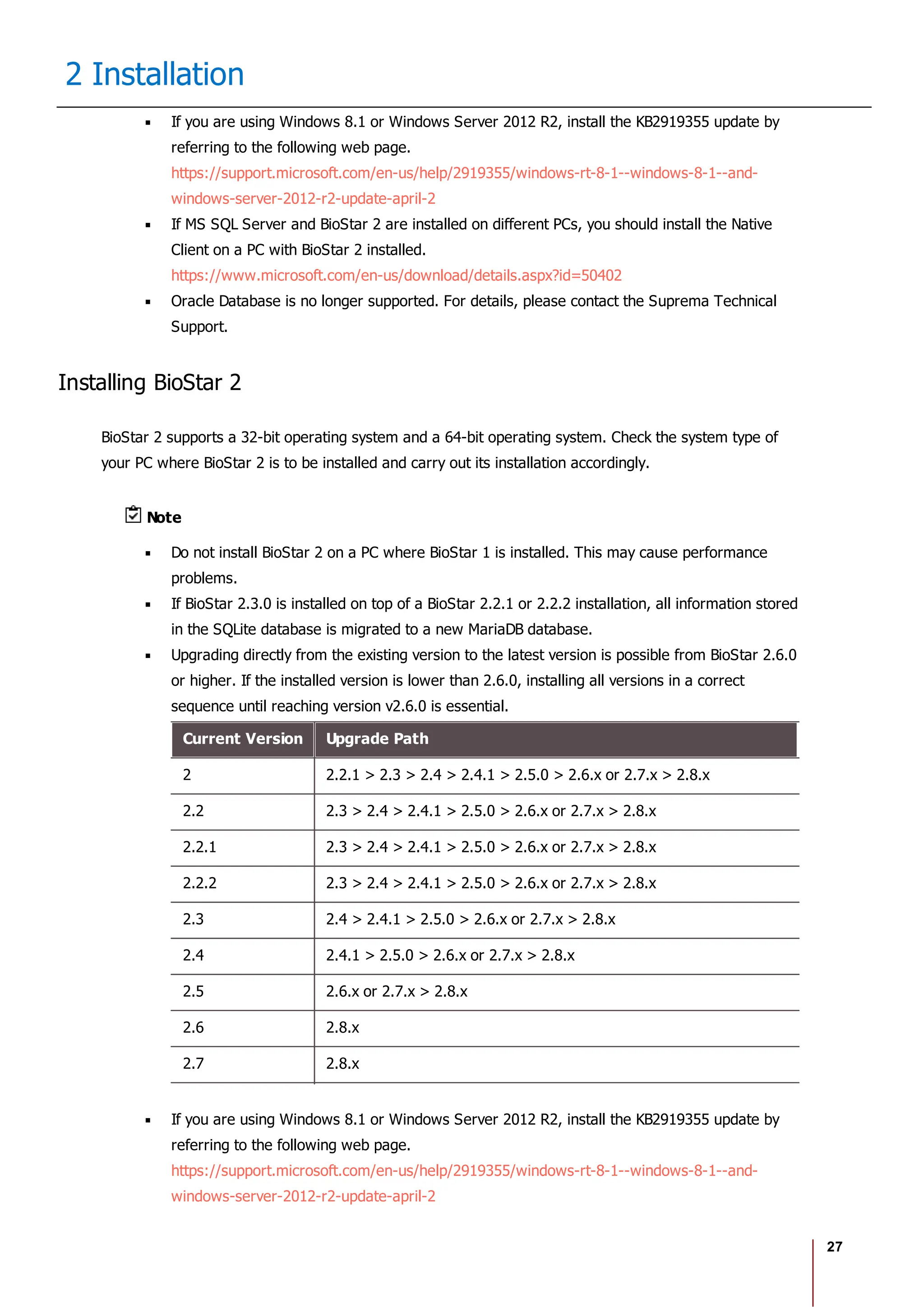
If you are using MS SQL 2014 Express, install the Service Pack 2 by referring to the following
web page.
https://www.microsoft.com/en-us/download/details.aspx?id=53168
If MS SQL Server and BioStar 2 are installed on different PCs, you should install the Native
Client on a PC with BioStar 2 installed.
https://www.microsoft.com/en-us/download/details.aspx?id=50402
When backing up a database from an older version of BioStar 2, disable all services and
procedures. Furthermore, if you do not back up and restore the AC database and the TA
database together, you will not be able to use the TA database.
If you want to back up the database of BioStar 2.8.1, be sure to also back up the enckey in
the Program Files BioStar 2 (x64) util folder. Otherwise, the database will be
unavailable.
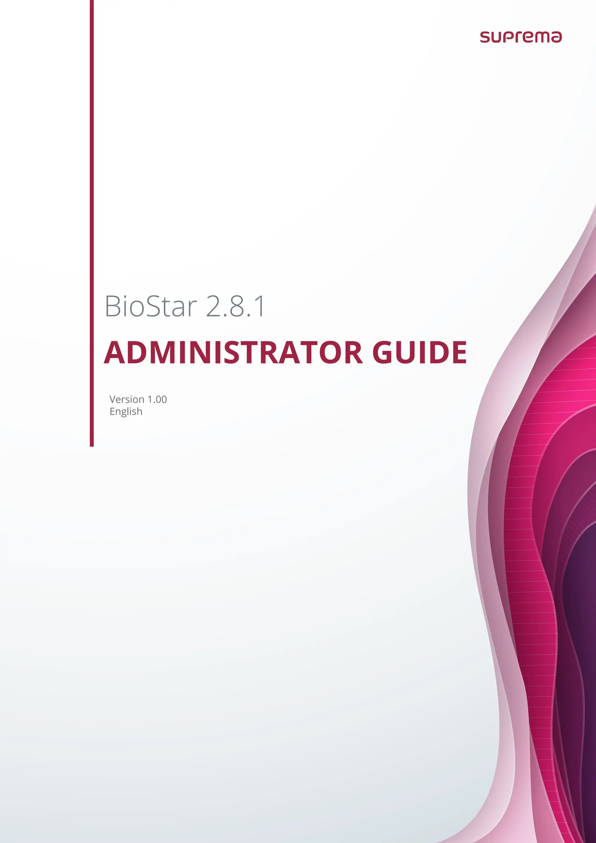
If you use a database configured by the user directly, check the following items before installing BioStar
2.
MariaDB
Open the my.cnf file and then change some configurations under
[mysqld] as shown below.
character-set-server=utf8
collation-server=utf8_unicode_ci
max_connections = 600
Open the my.cnf file and then add some configurations under [mysqld]
as shown below.
log_bin_trust_function_creators = 1
group_concat_max_len = 102400
Access MariaDB with the root permission and execute the following
command.
> GRANT SUPER ON . TO user_id@'localhost' IDENTIFIED BY "password";
> GRANT SUPER ON . TO user_id@'%' IDENTIFIED BY "password";
MS SQL Server
Setting the port
a) Run SQL Server Configuration Manager and set TCP/IP Protocol
for Protocols for SQLEXPRESS to the desired port number.](https://image.slidesharecdn.com/biostar2administratorguidev1-240423133223-f59417ad/75/BioStar2_Administrator_Guide_V1-8-1_EN-pdf-34-2048.jpg)
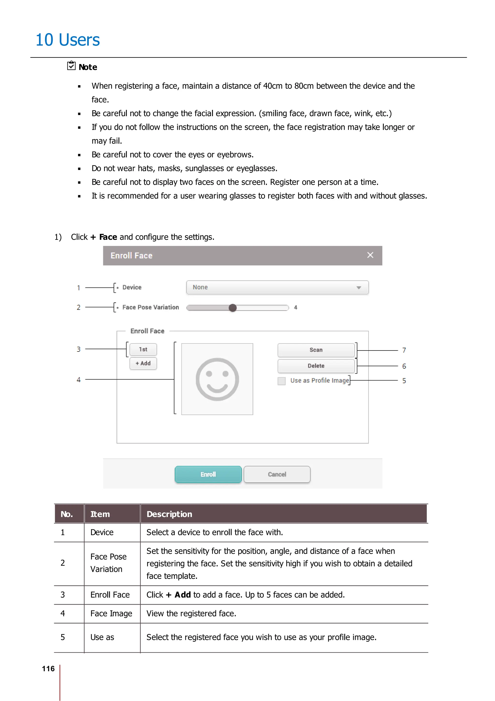
![117
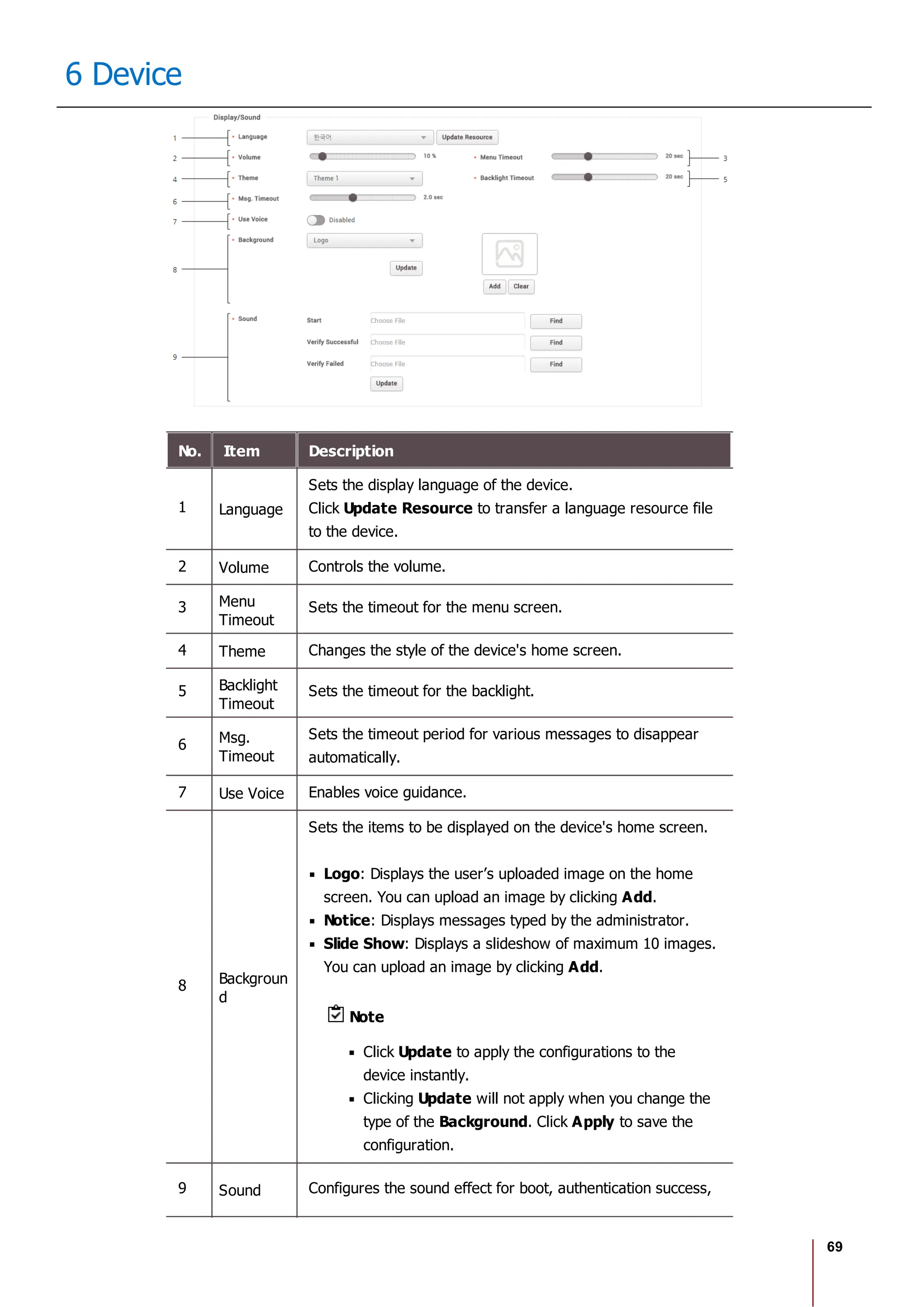
10 Users
No. Item Description
Profile
Image
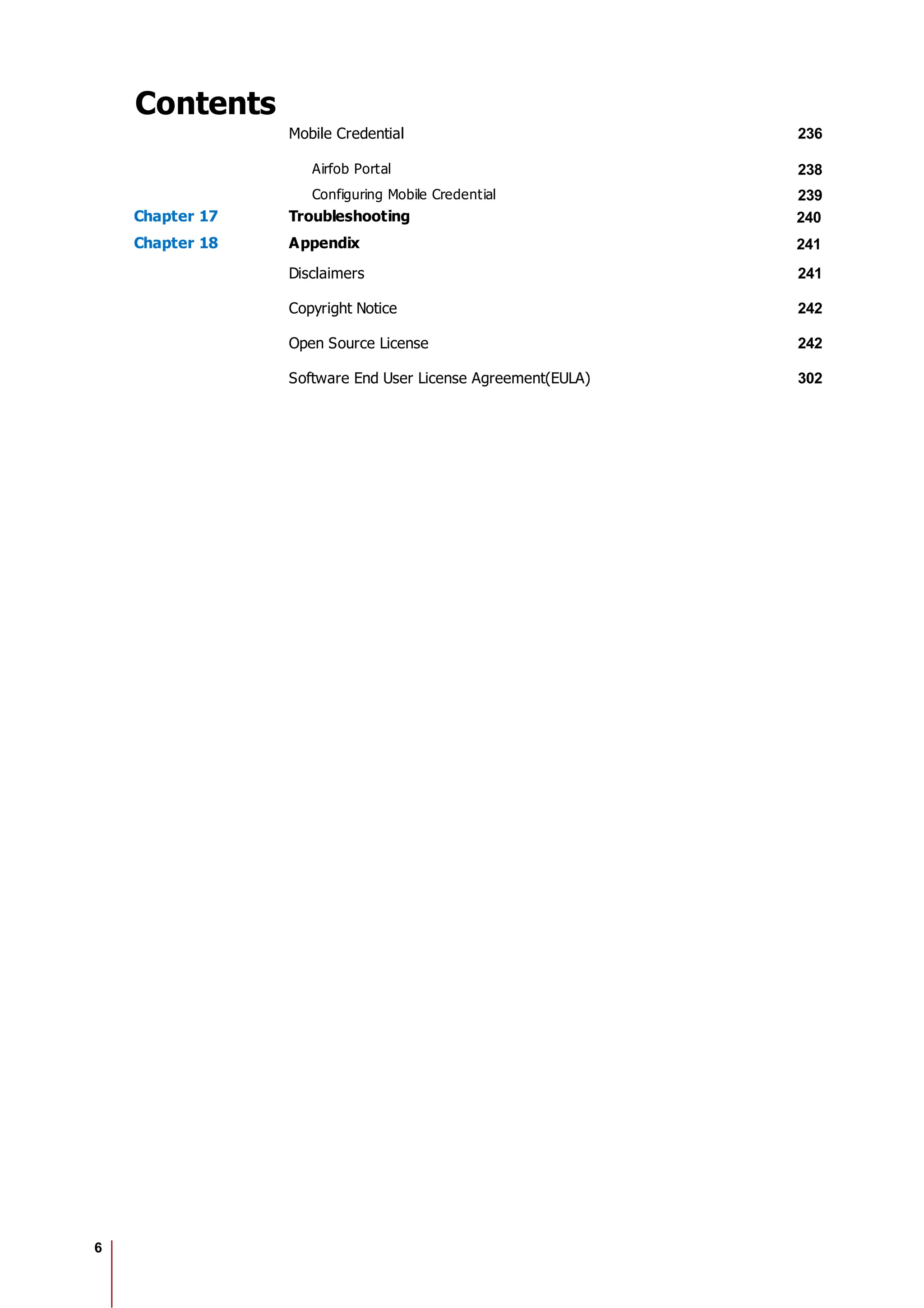
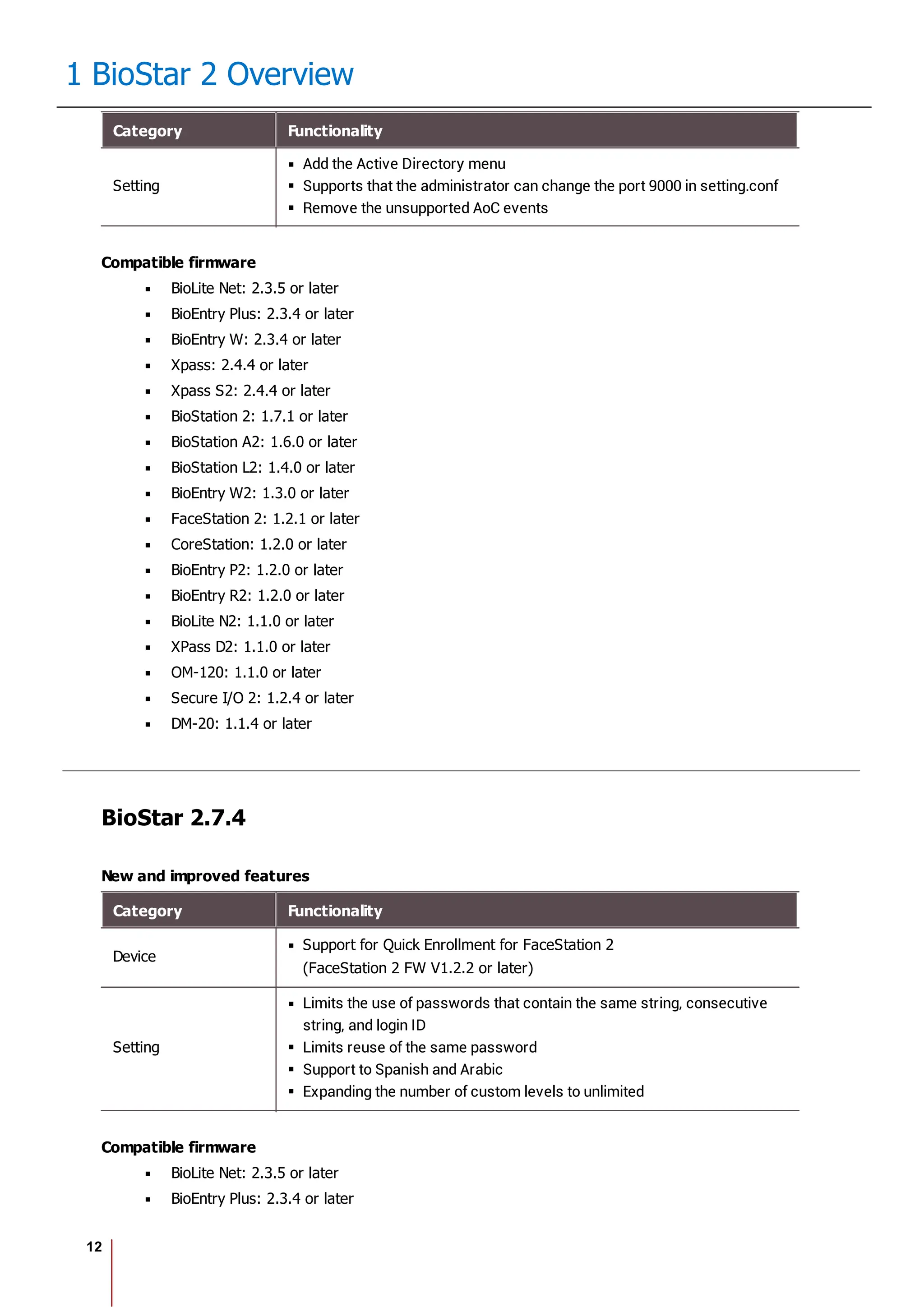
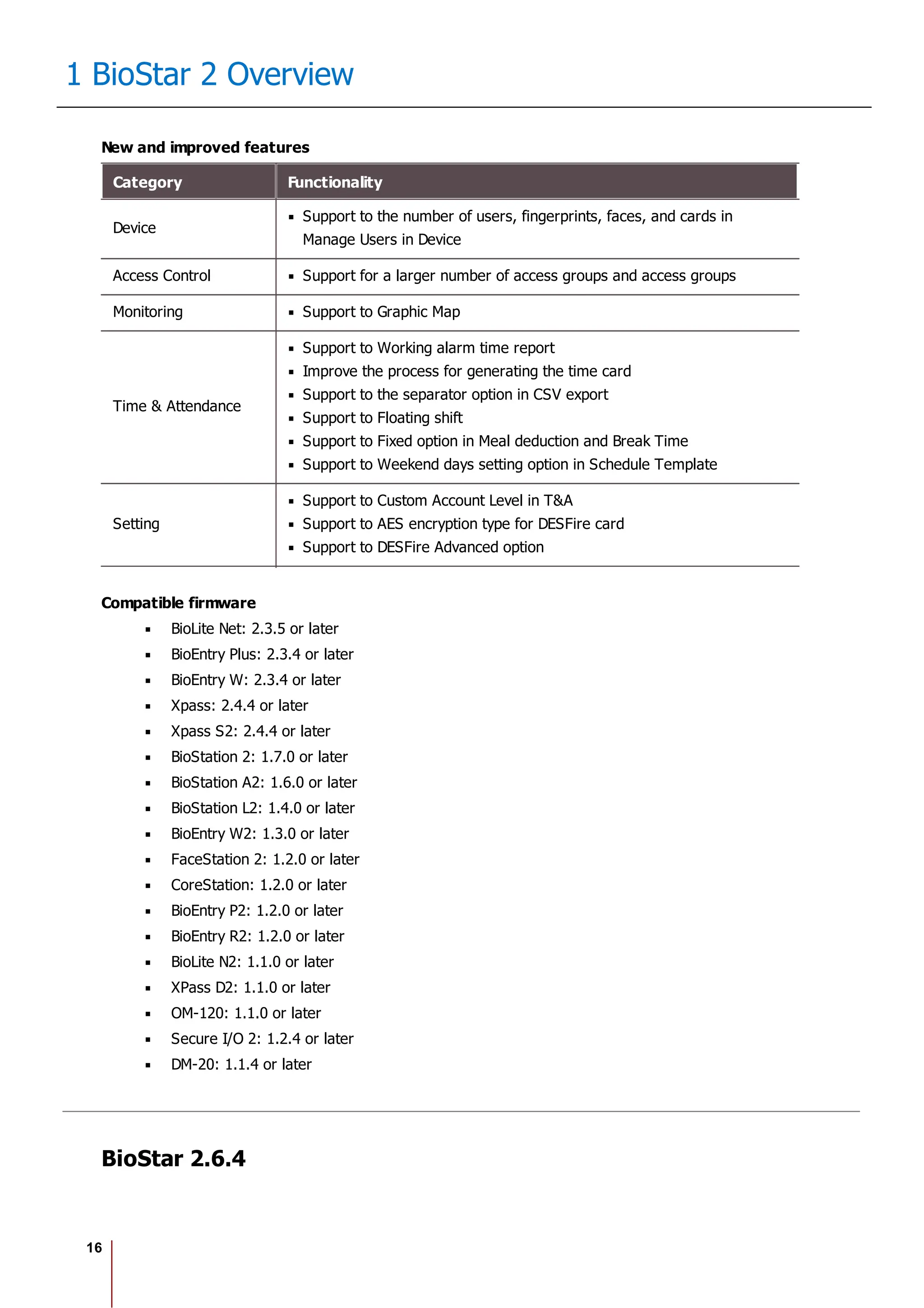
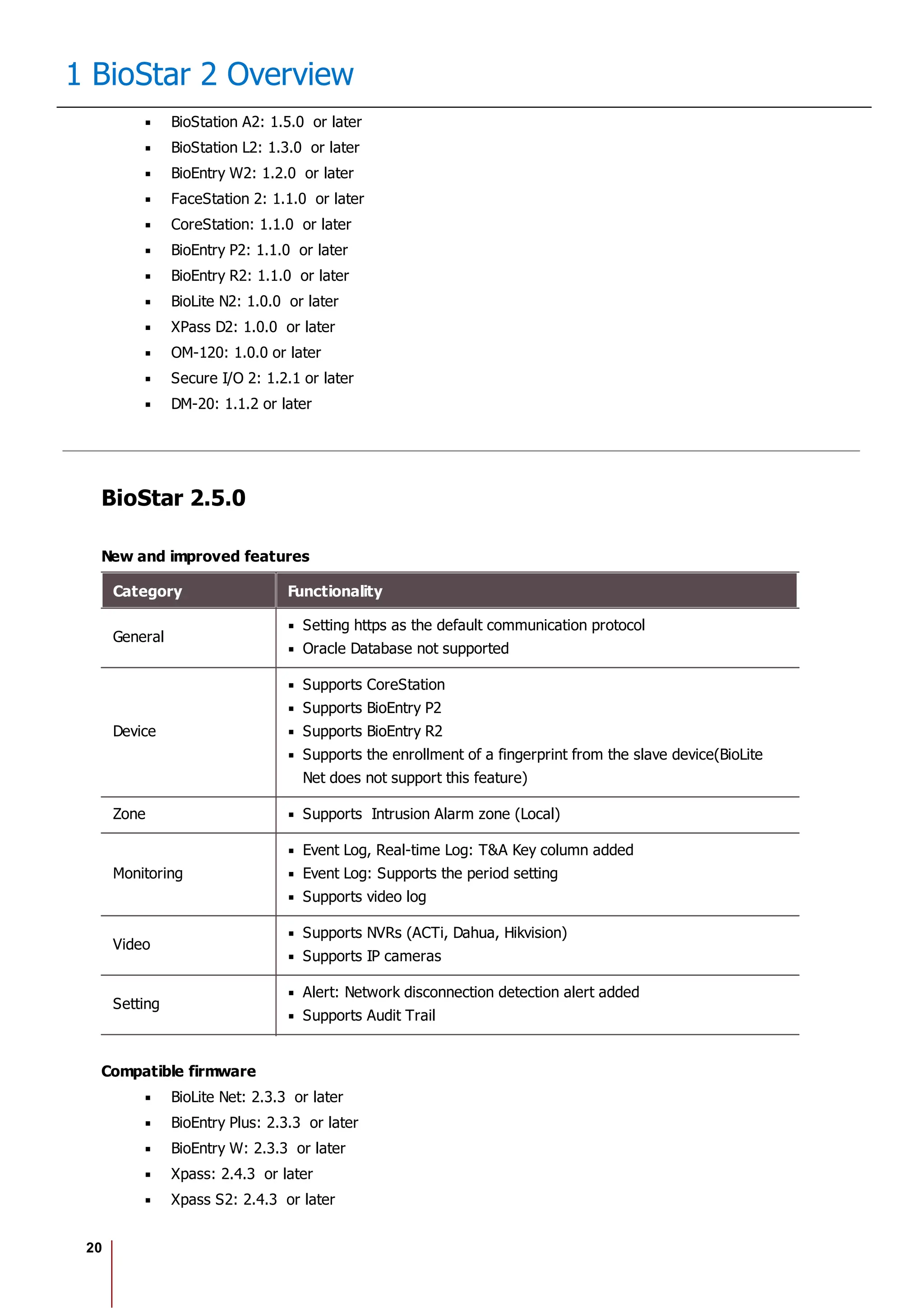
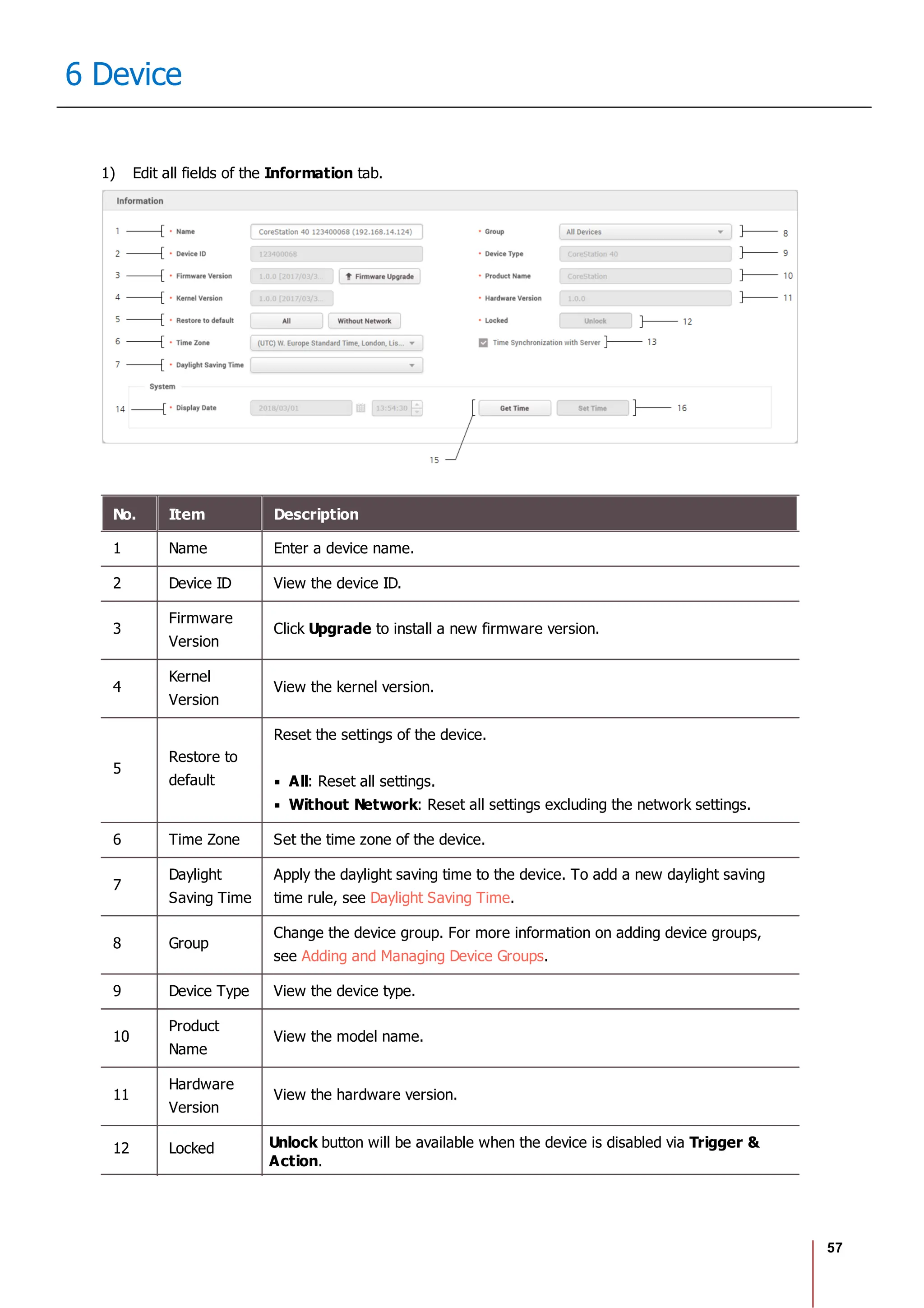
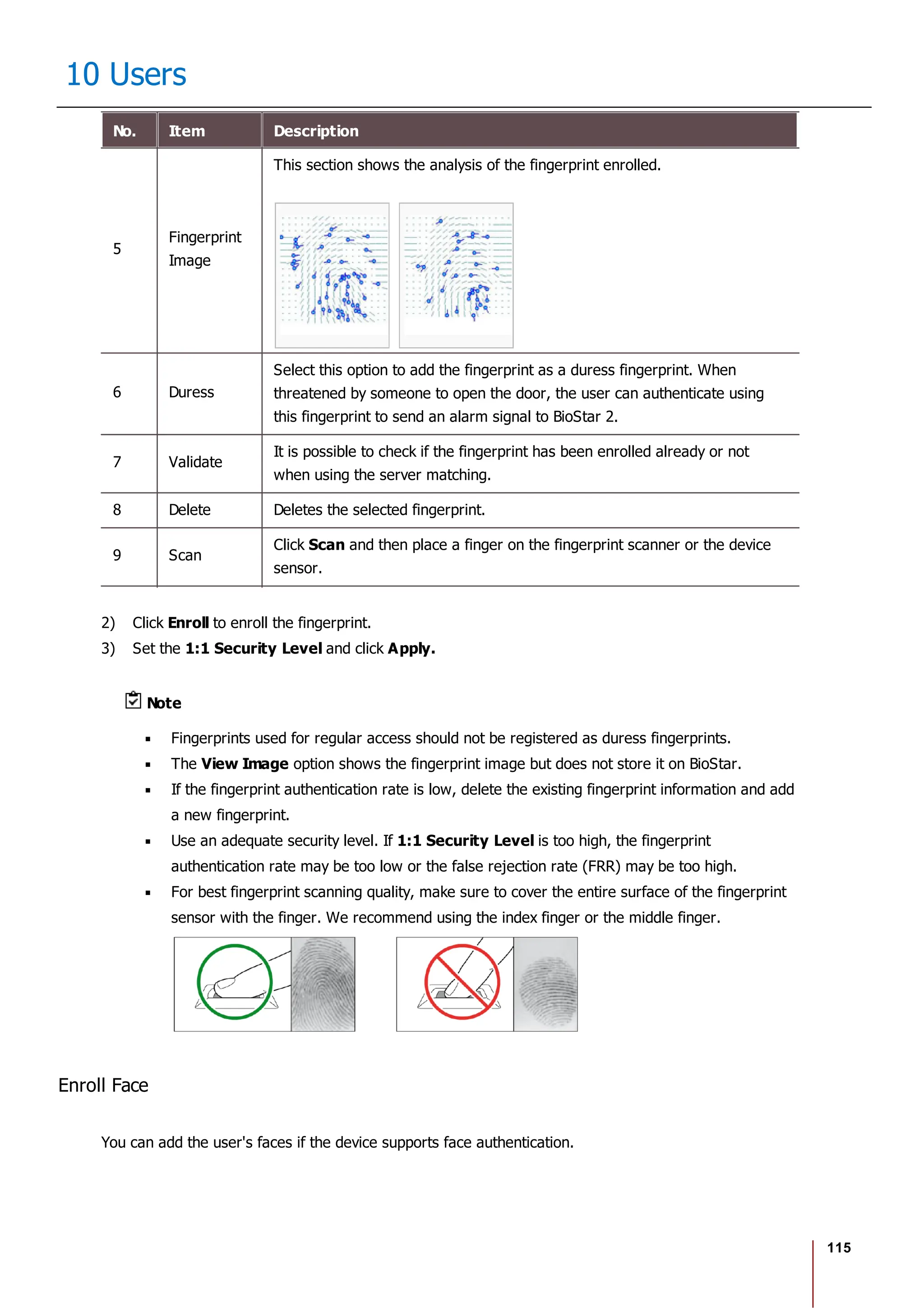
6 Delete Deletes the selected face.
7 Scan Click Scan and then follow the instructions on the device screen to scan.
2) Click Enroll to enroll the face.
3) Set the 1:1 Security Level and click Apply.
Note
If the face authentication rate is low, delete the existing face information and add a new face.
Use an adequate security level. If 1:1 Security Level is too high, the authentication rate may
be too low or the false rejection rate (FRR) may be too high.
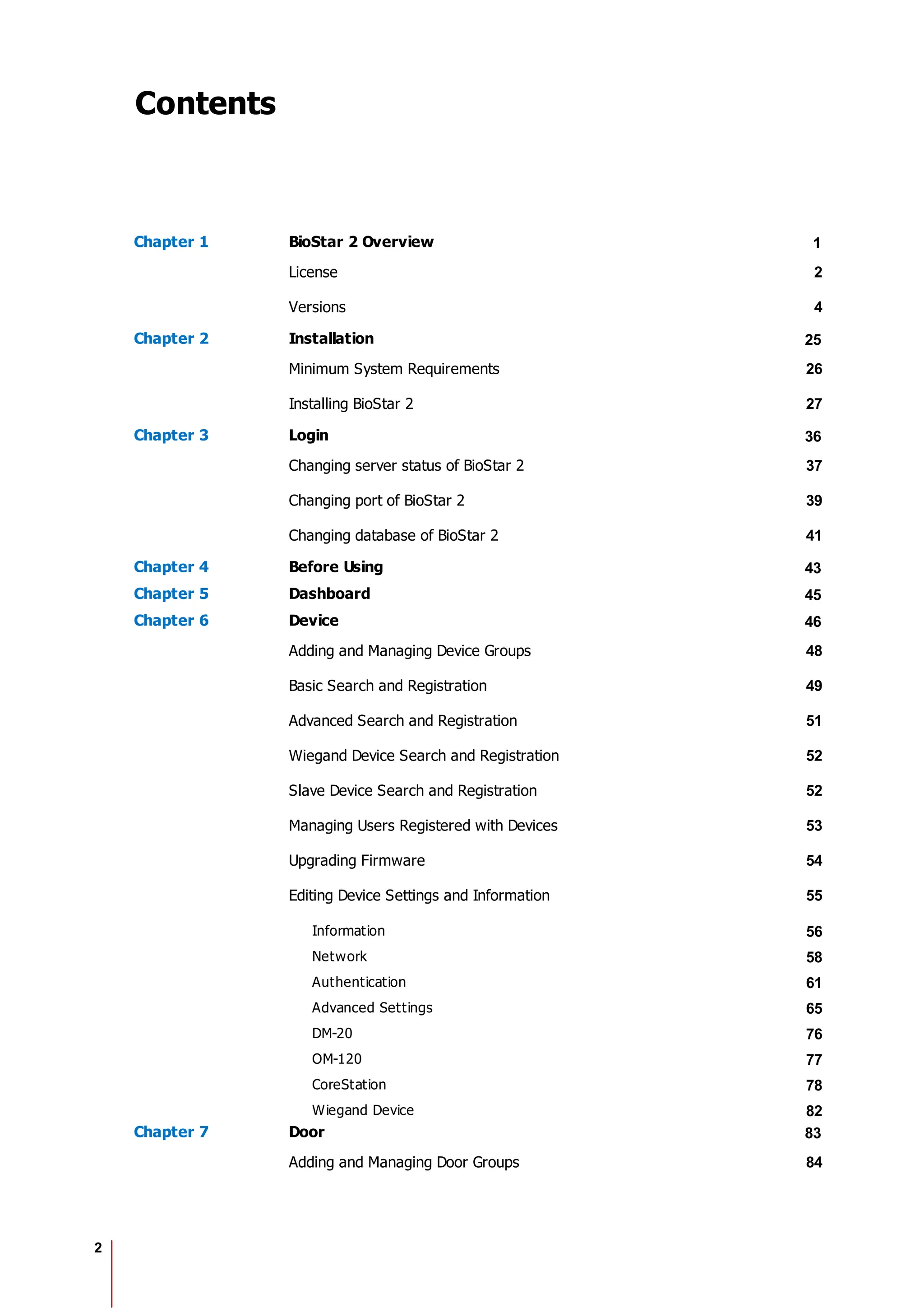
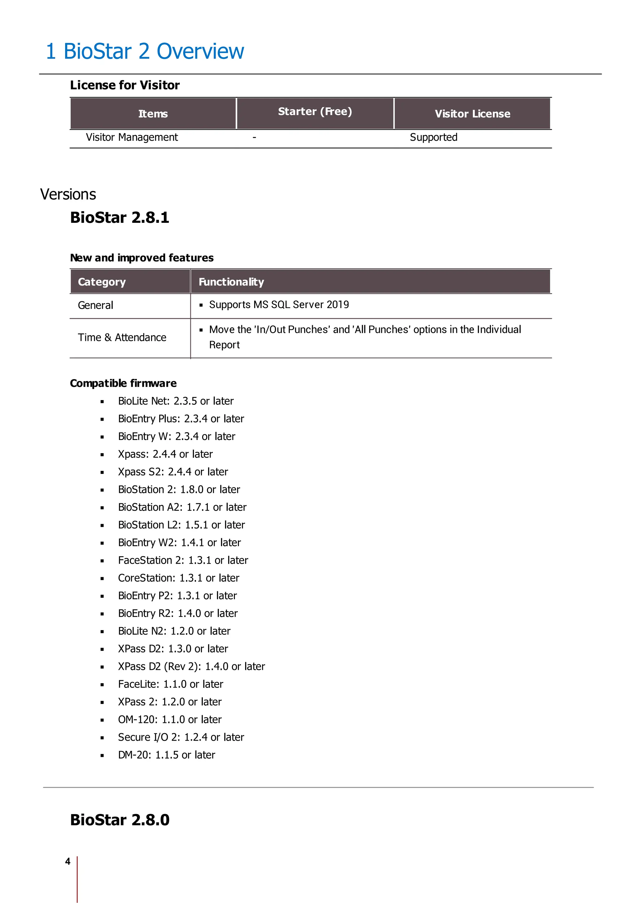
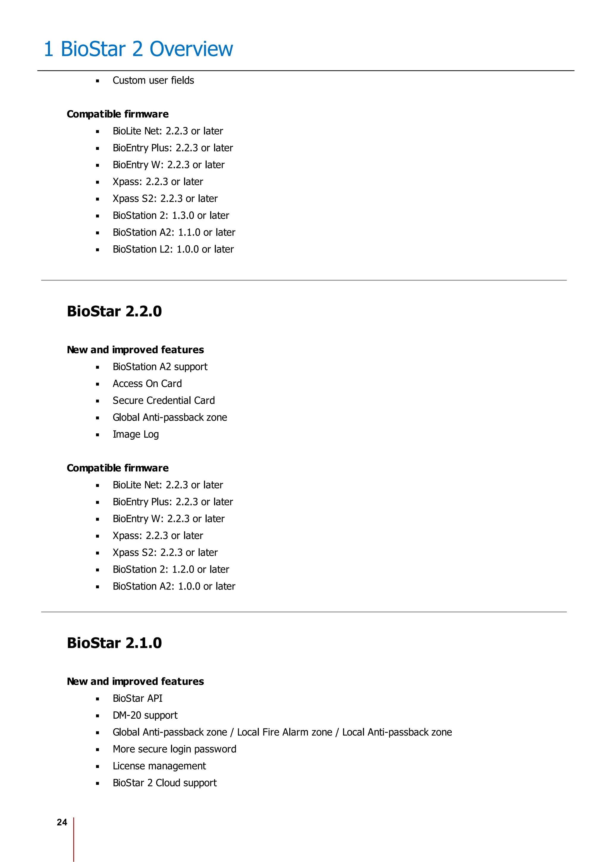
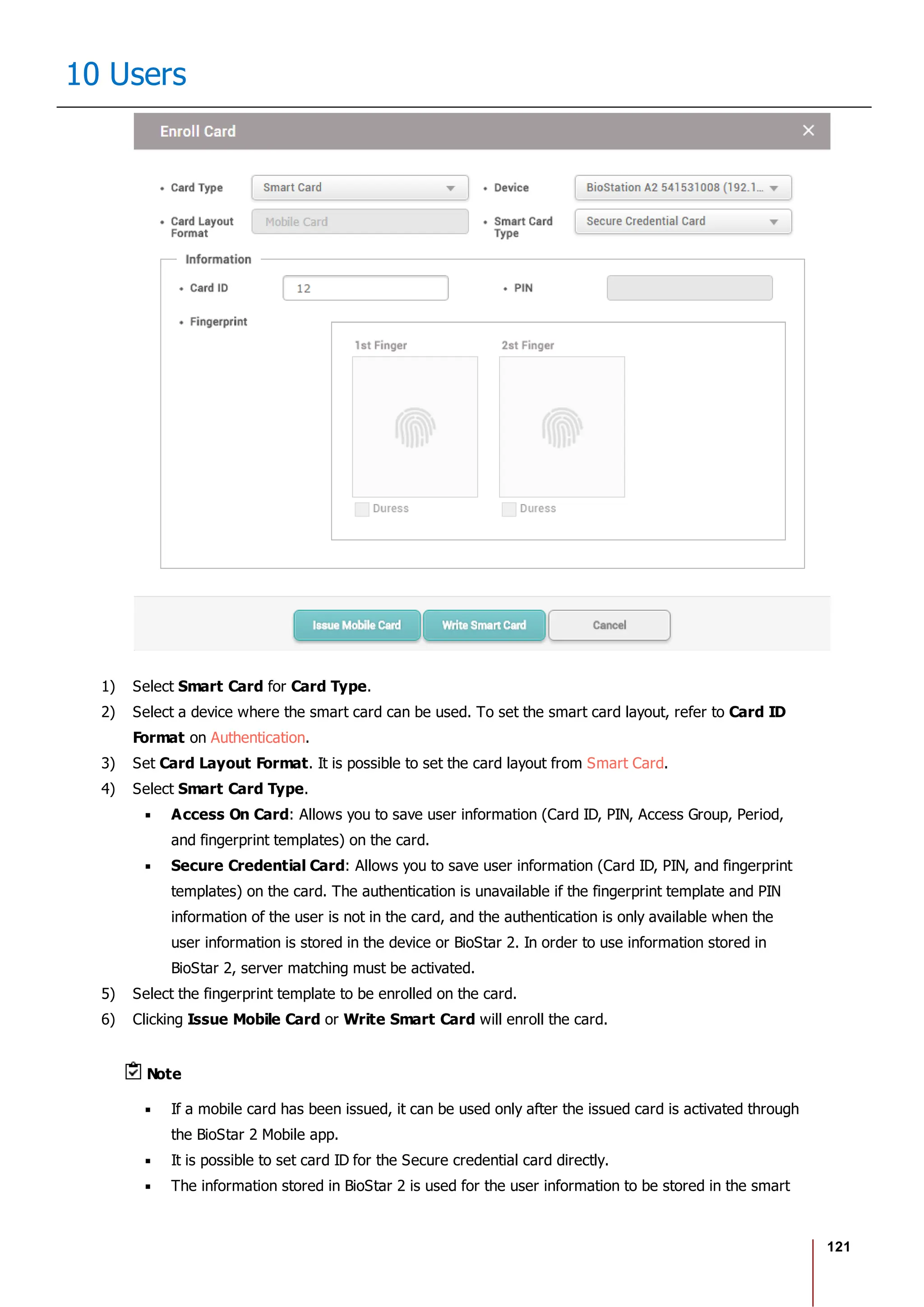
Enroll Card
You can assign access cards to users or manage the existing cards.
For the types of card supported by the device, refer to the device manual.
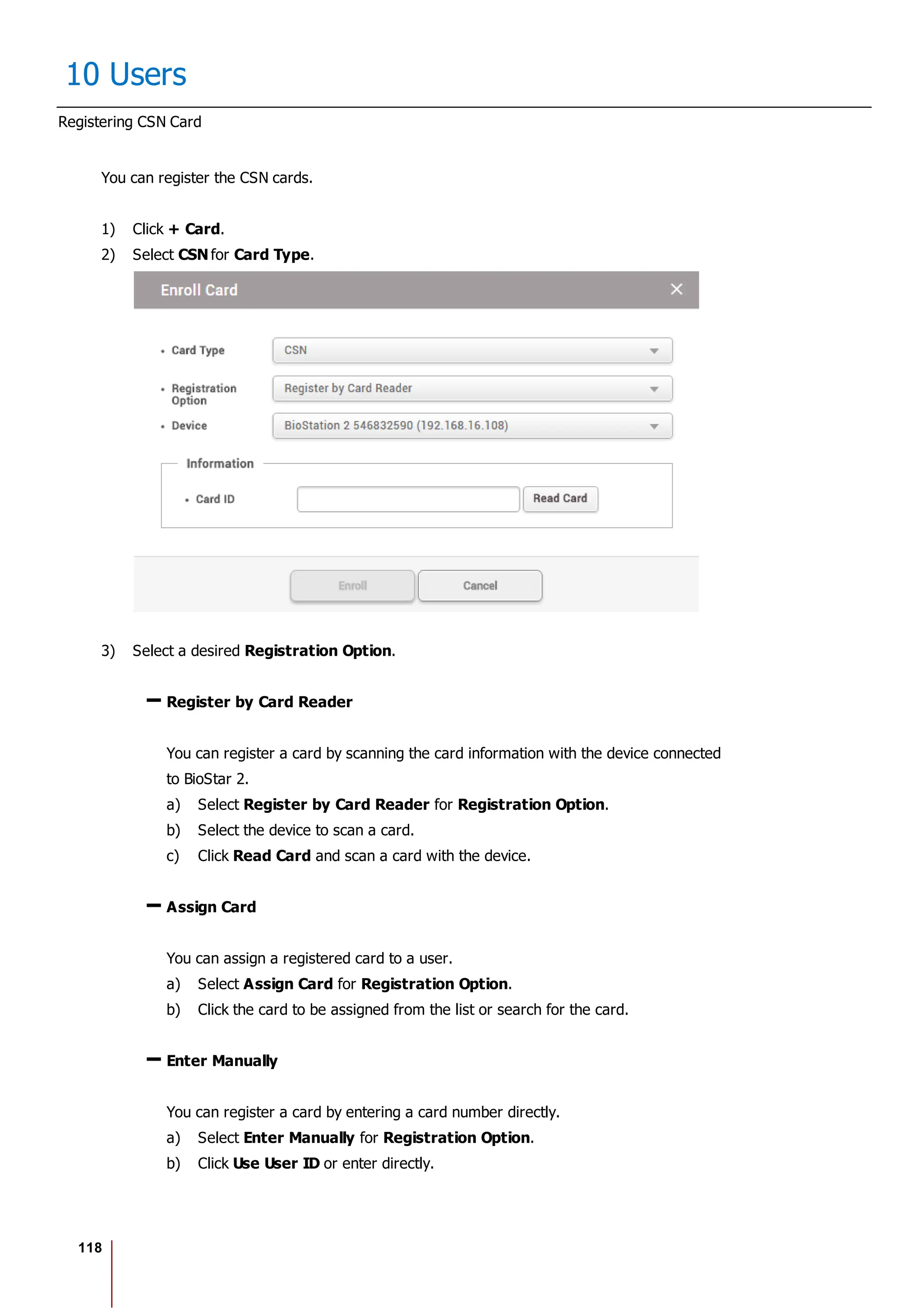
Registering CSN Card
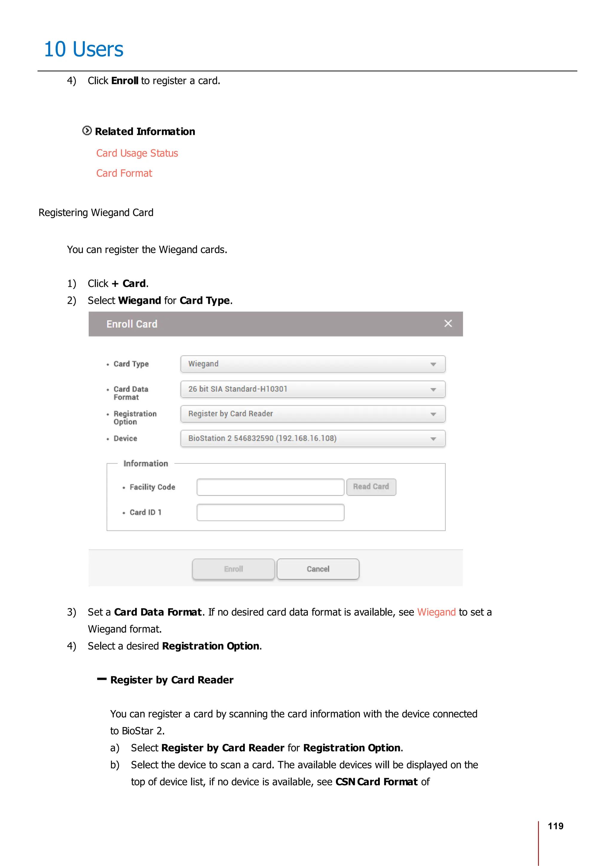
Registering Wiegand Card
Registering Smart / Mobile Cards
[Card Enrollment using the USB Agent]
Card Type CSN Wiegand Smart Card
EM X X X
MIFARE O X O
DESFire O X O
FeliCa O X X
HID Prox X X X
HID iCLASS X X X](https://image.slidesharecdn.com/biostar2administratorguidev1-240423133223-f59417ad/75/BioStar2_Administrator_Guide_V1-8-1_EN-pdf-123-2048.jpg)
![175
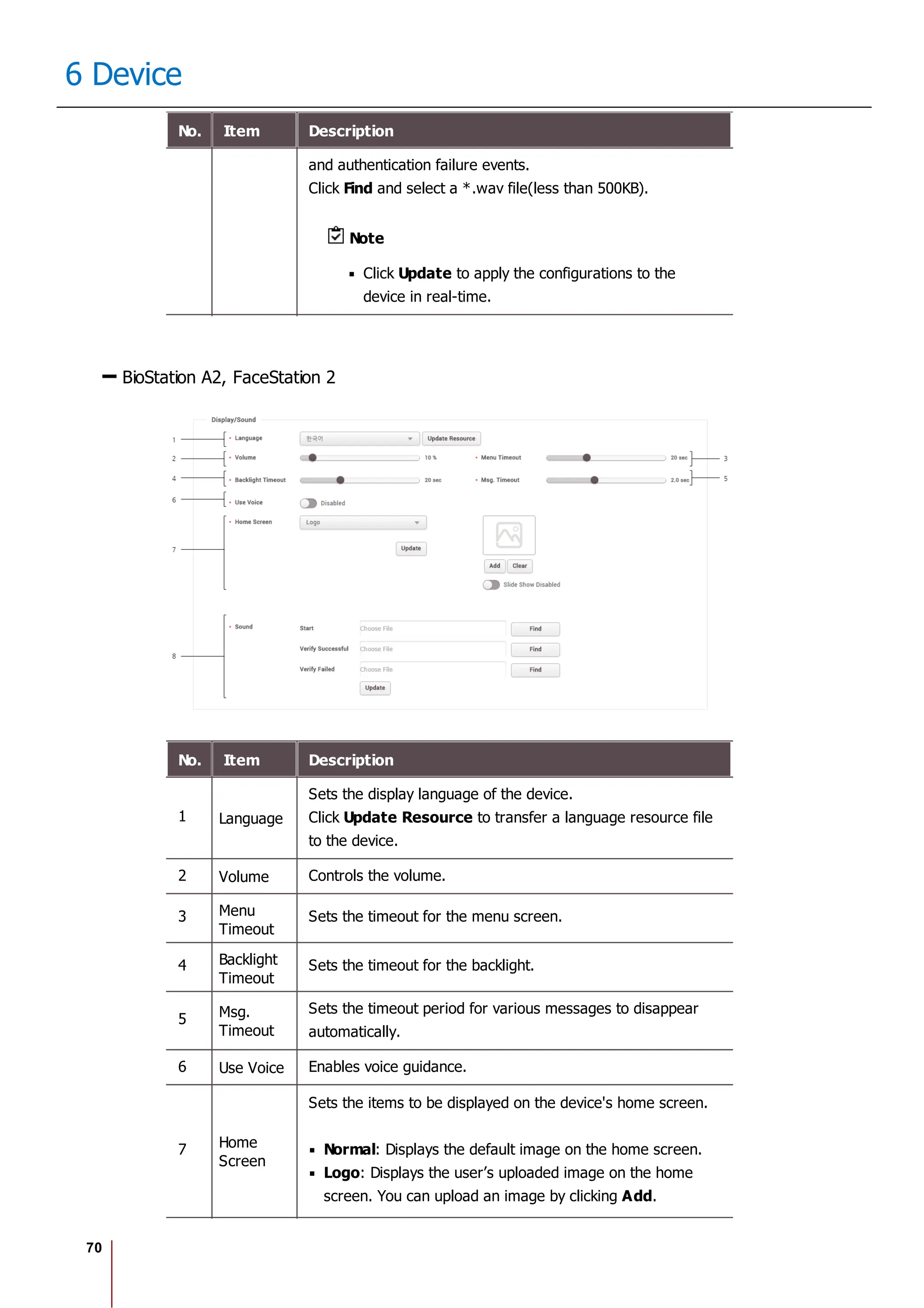
14 Time & Attendance
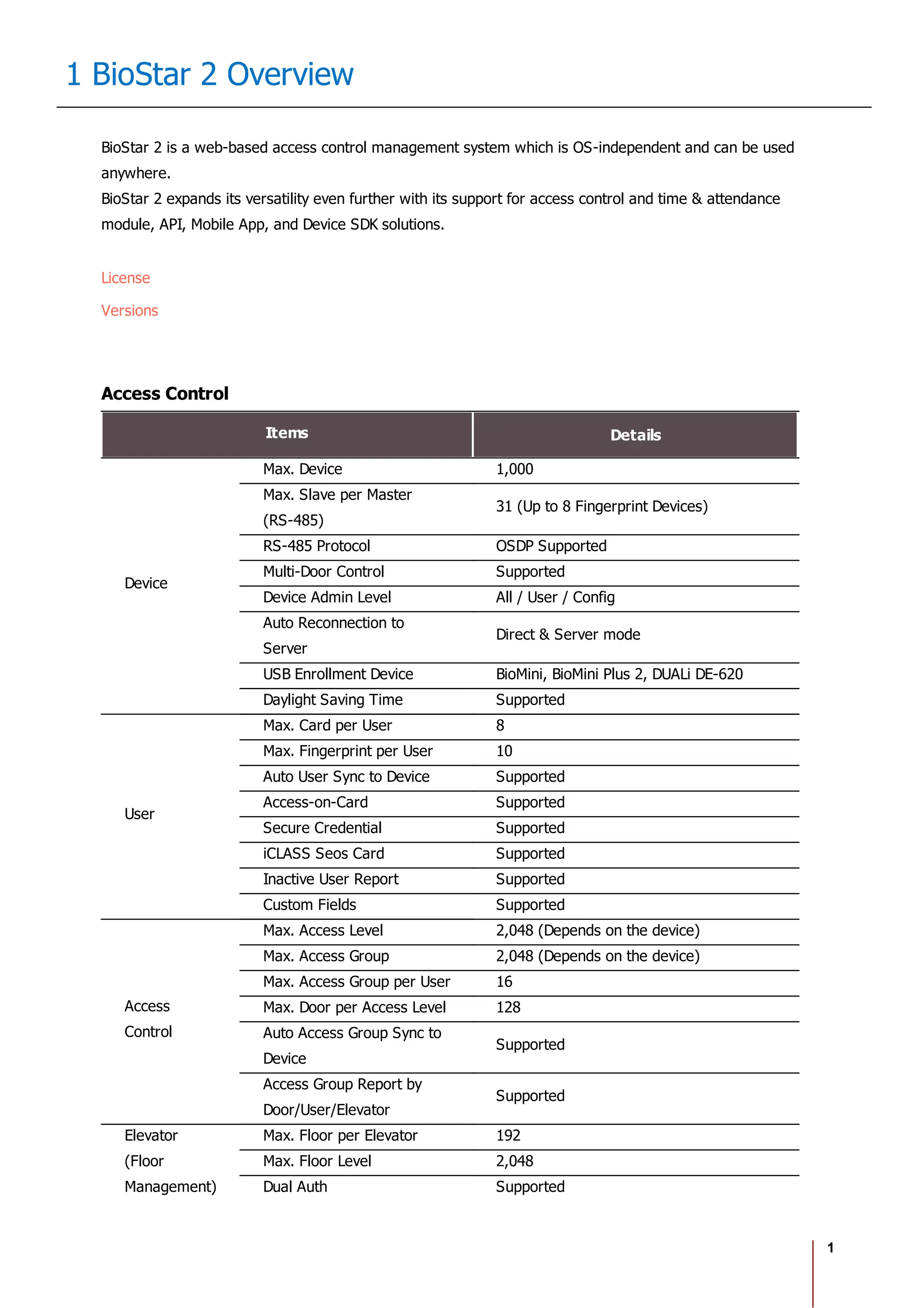
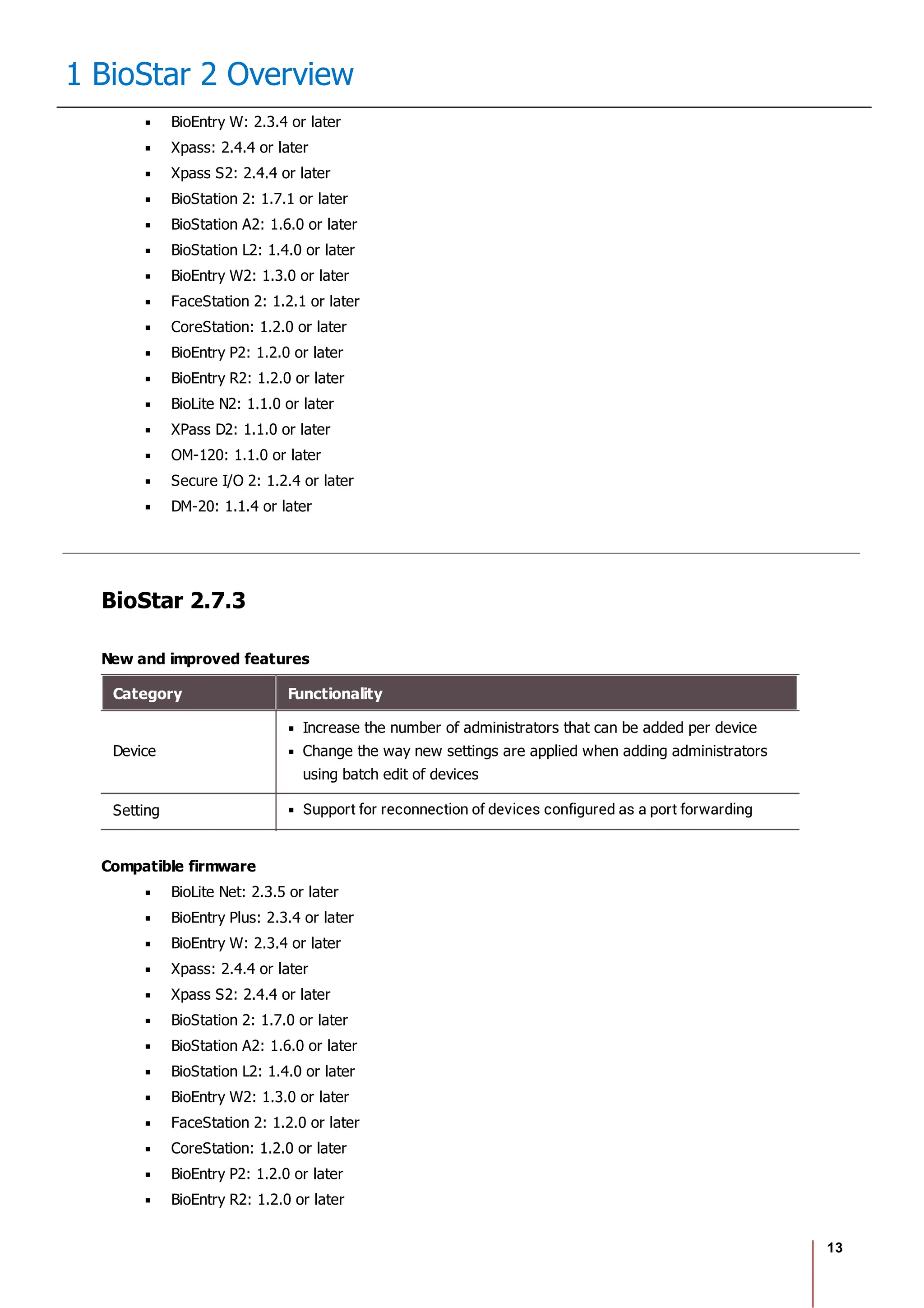
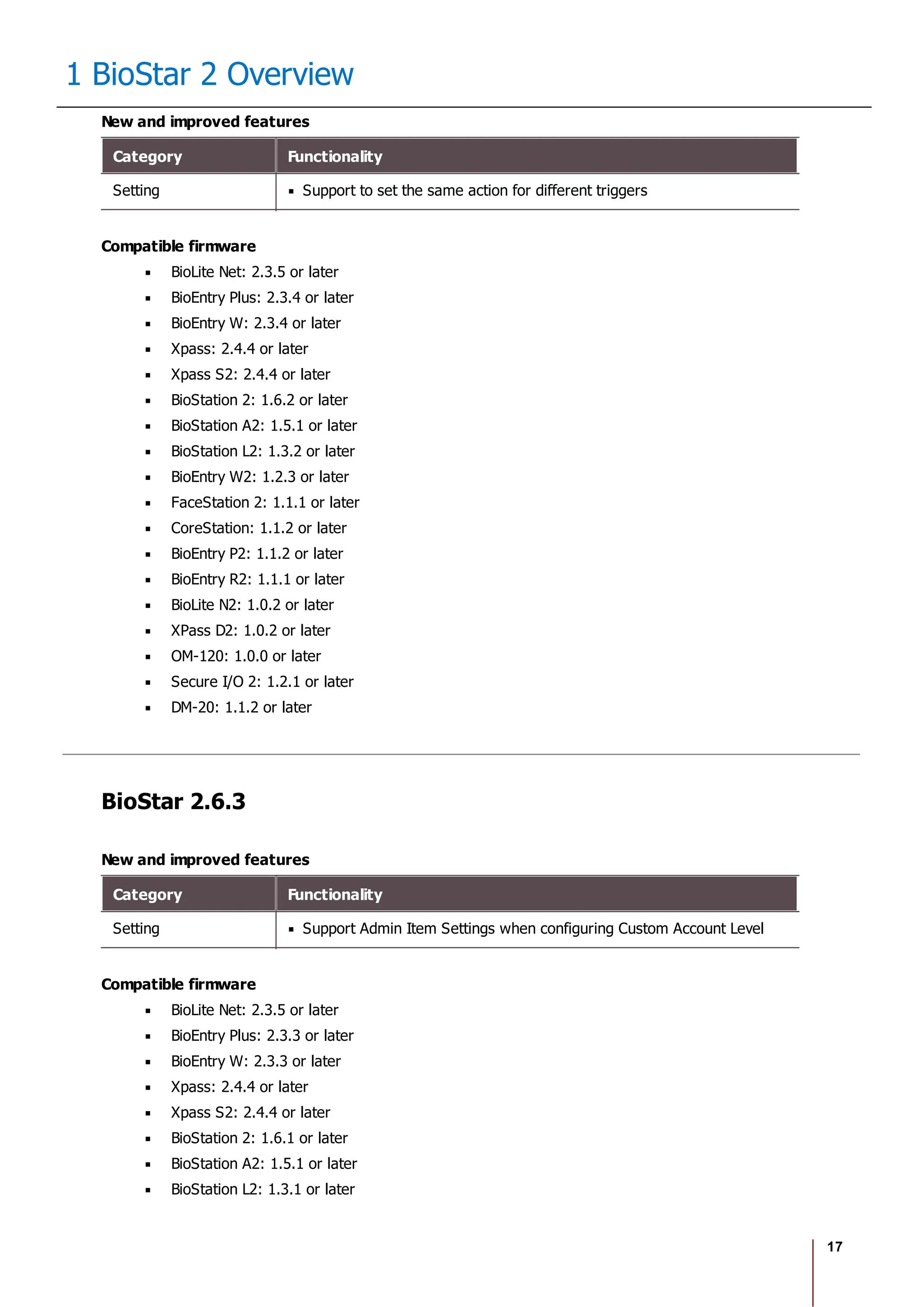
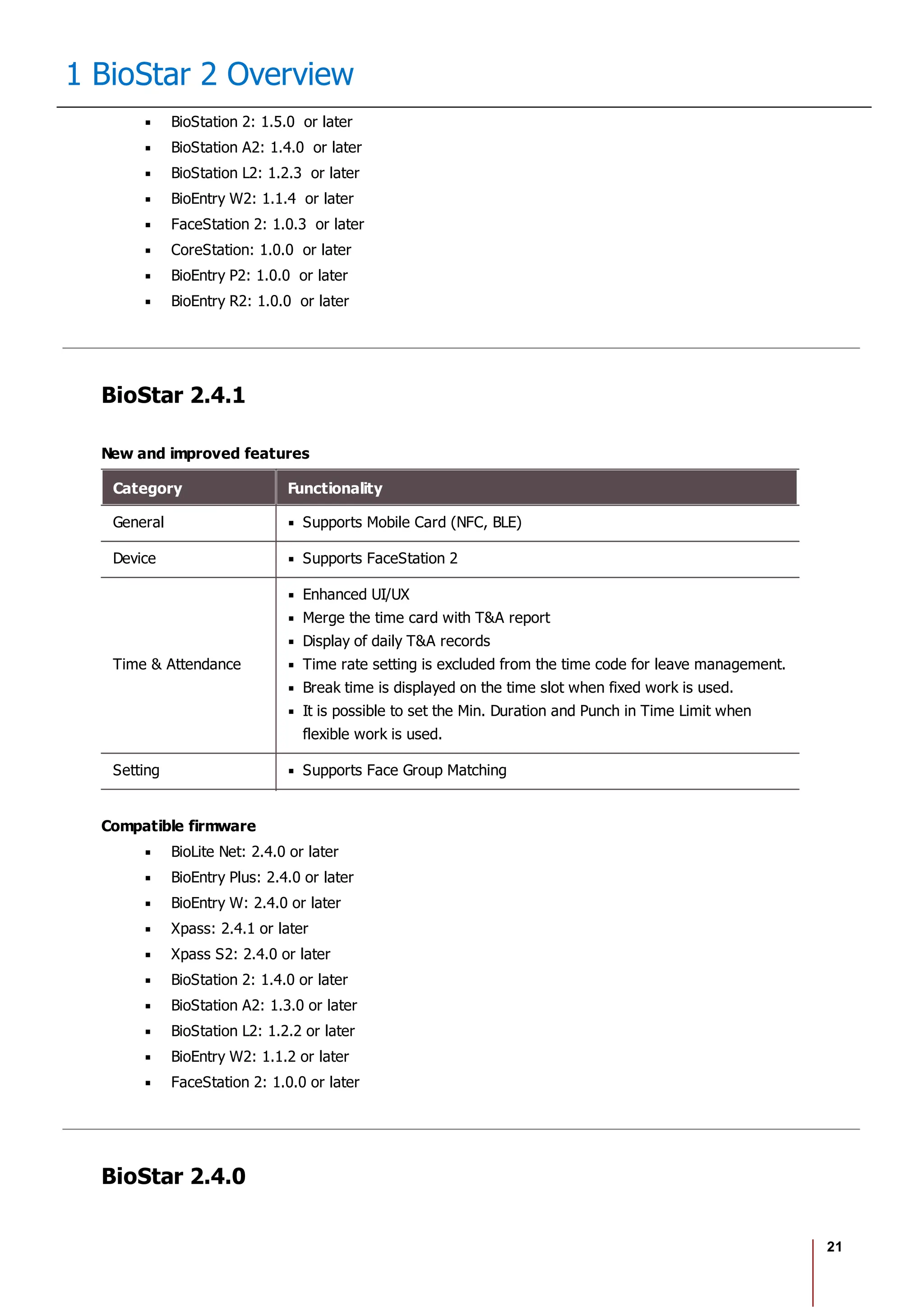
2) Select Add Leave and set each item. To apply it to other users equally, add a
user by clicking .
3) When you click OK, the leave will be registered on the set period.
4) To delete a leave, click the registered leave and click Yes.
Note
If there is no desired leave management Time code, add one by referring
to the Time Code.
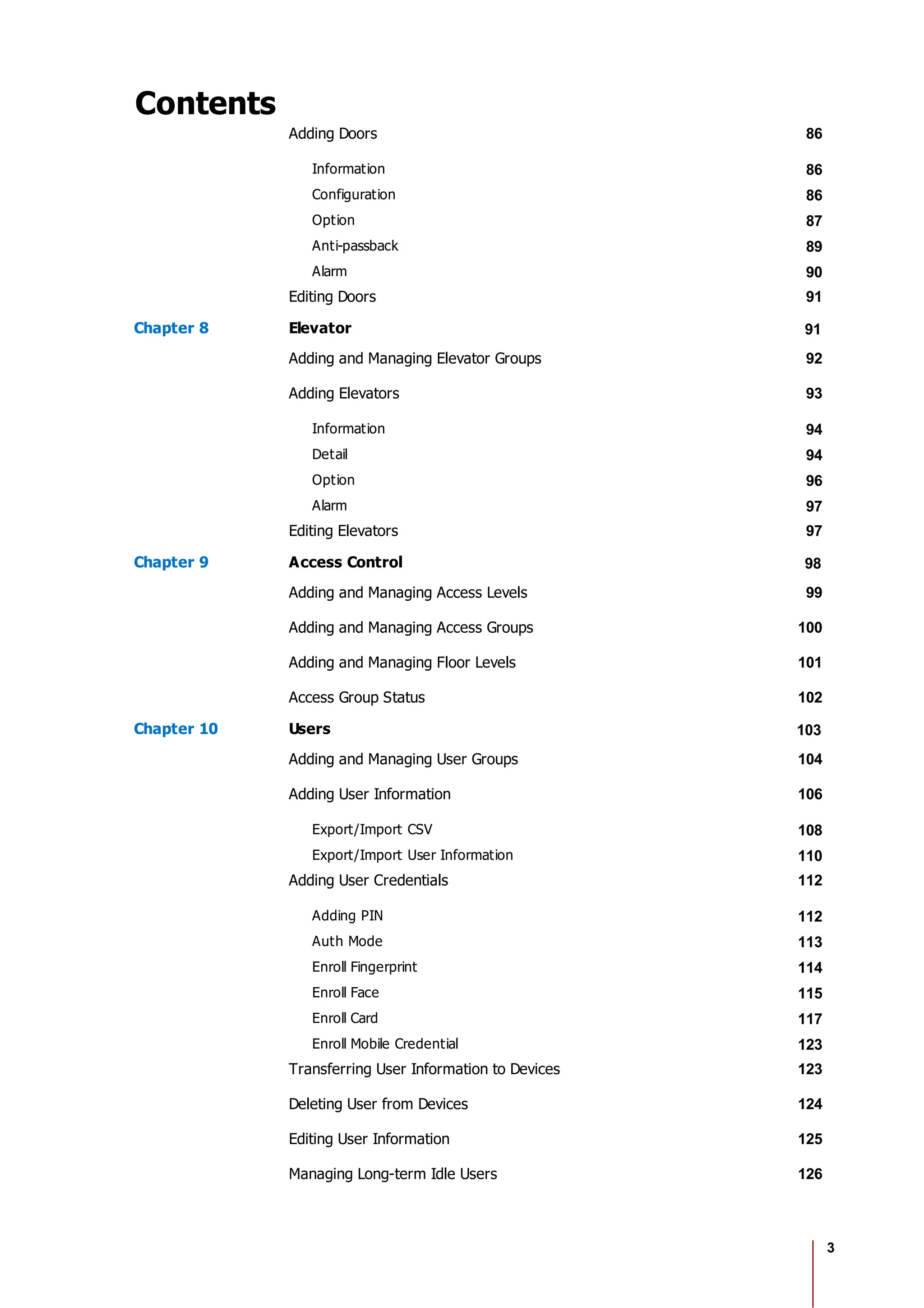
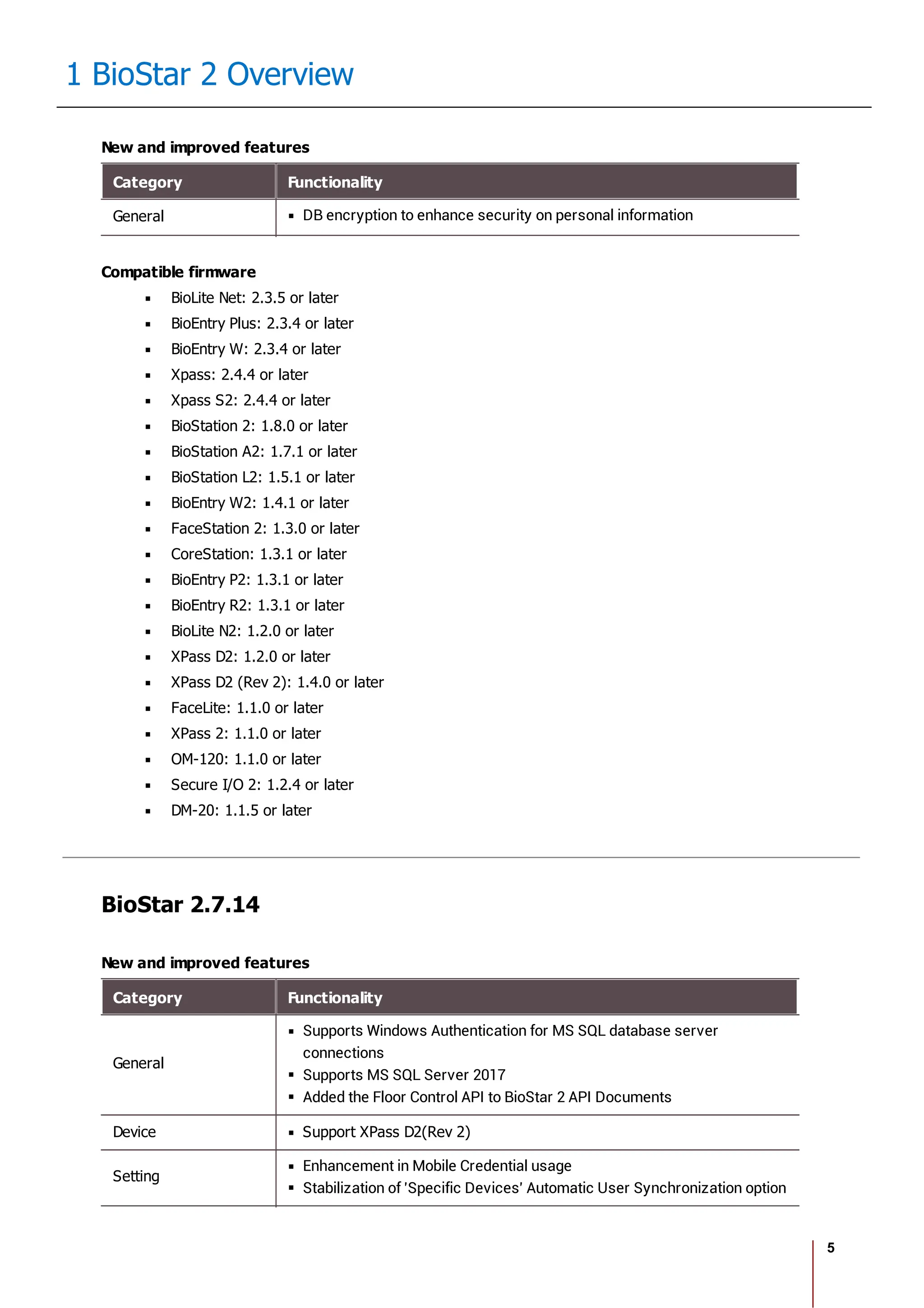
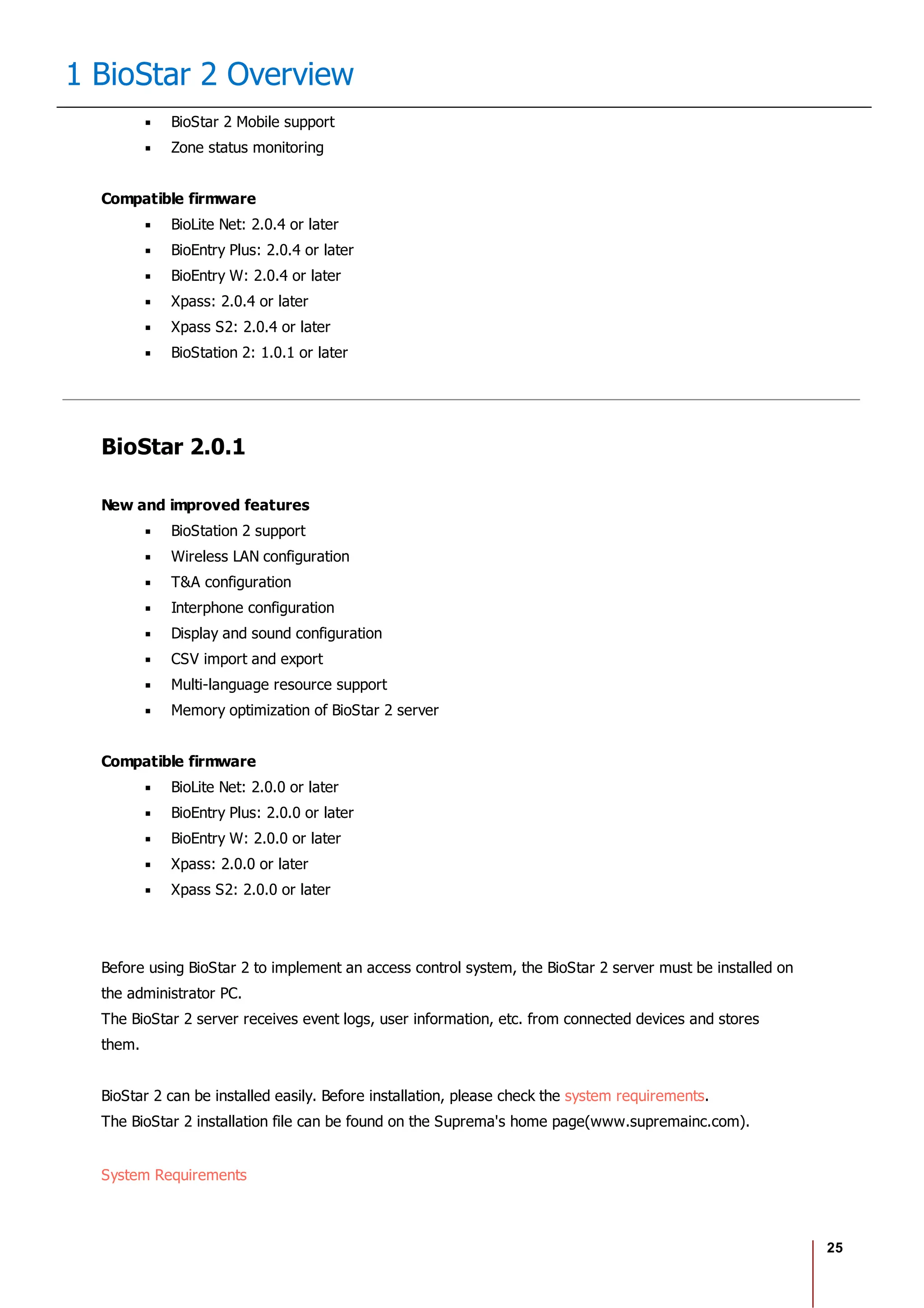
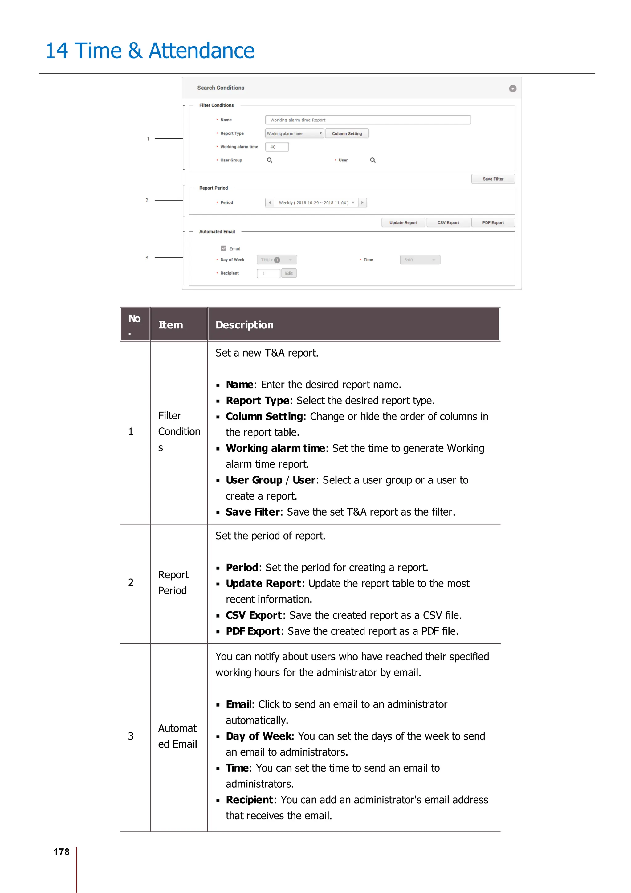
Report
You can create a T&A report with T&A events of a user collected through the system, and edit or export
time records as a CSV file or a PDF file.
7 preset report filters can be used conveniently, or the administrator can set the filter manually.
Before Using the Multilingual Report
BioStar 2 supports Korean and English language. To use multilingual report, please
check the following.
Font Setting
1. Go to [C: Program Files BioStar 2(x64) ta dist setup report_fonts].
2. Create a folder with the language name you want to use. Refer to the ISO 639-
1 standard for language name. For example, to use Spanish, create a folder
named "es".
3. Copy and paste the font file into the folder you created. Only one TrueType Font
is supported.](https://image.slidesharecdn.com/biostar2administratorguidev1-240423133223-f59417ad/75/BioStar2_Administrator_Guide_V1-8-1_EN-pdf-181-2048.jpg)
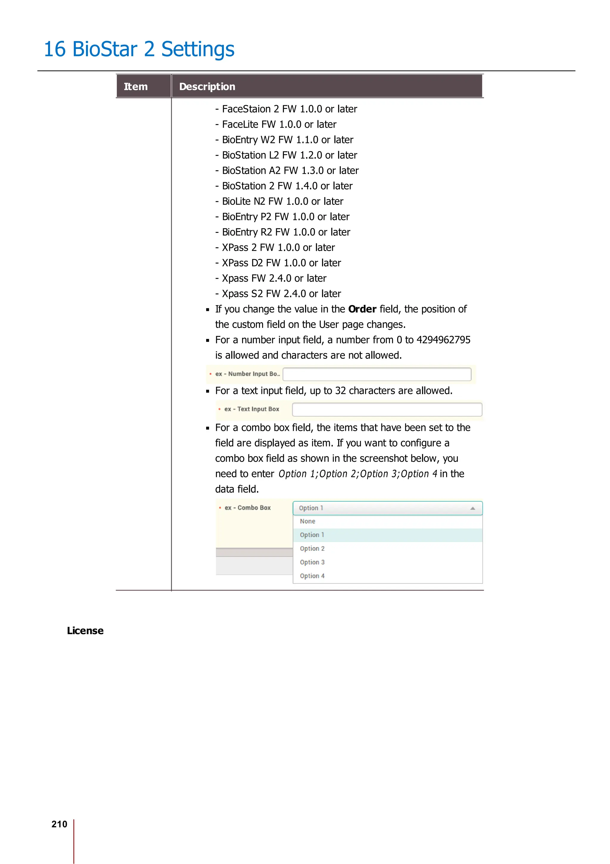
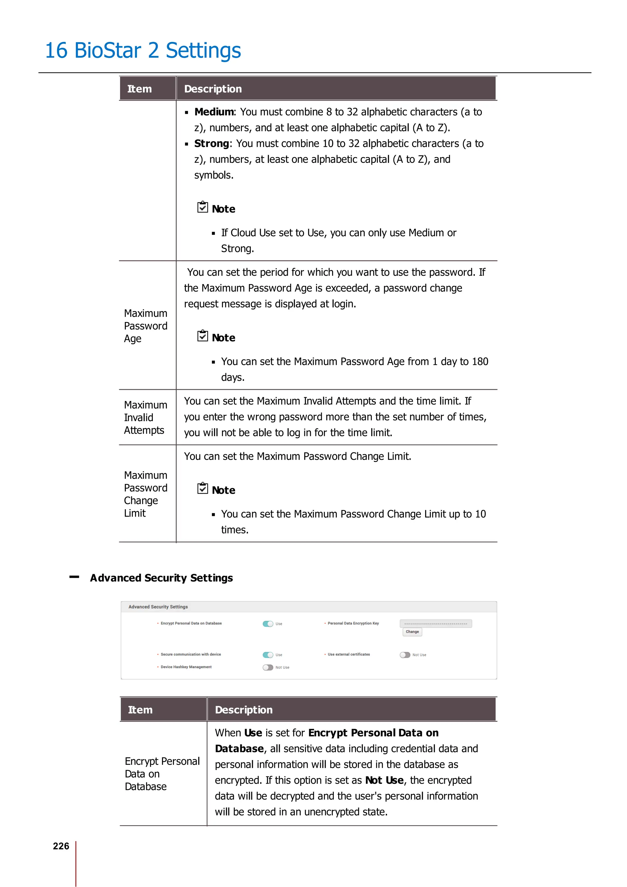
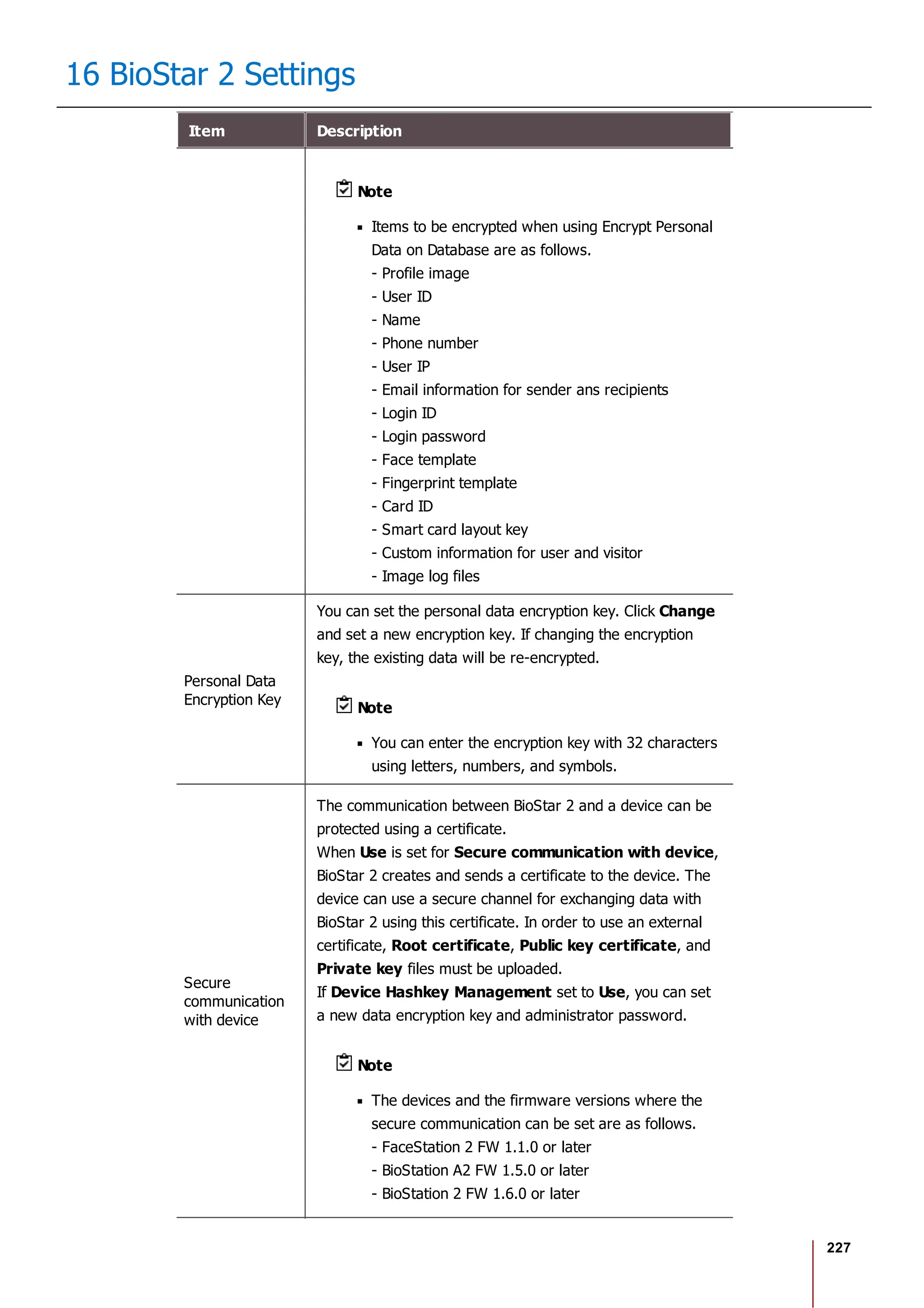
![228
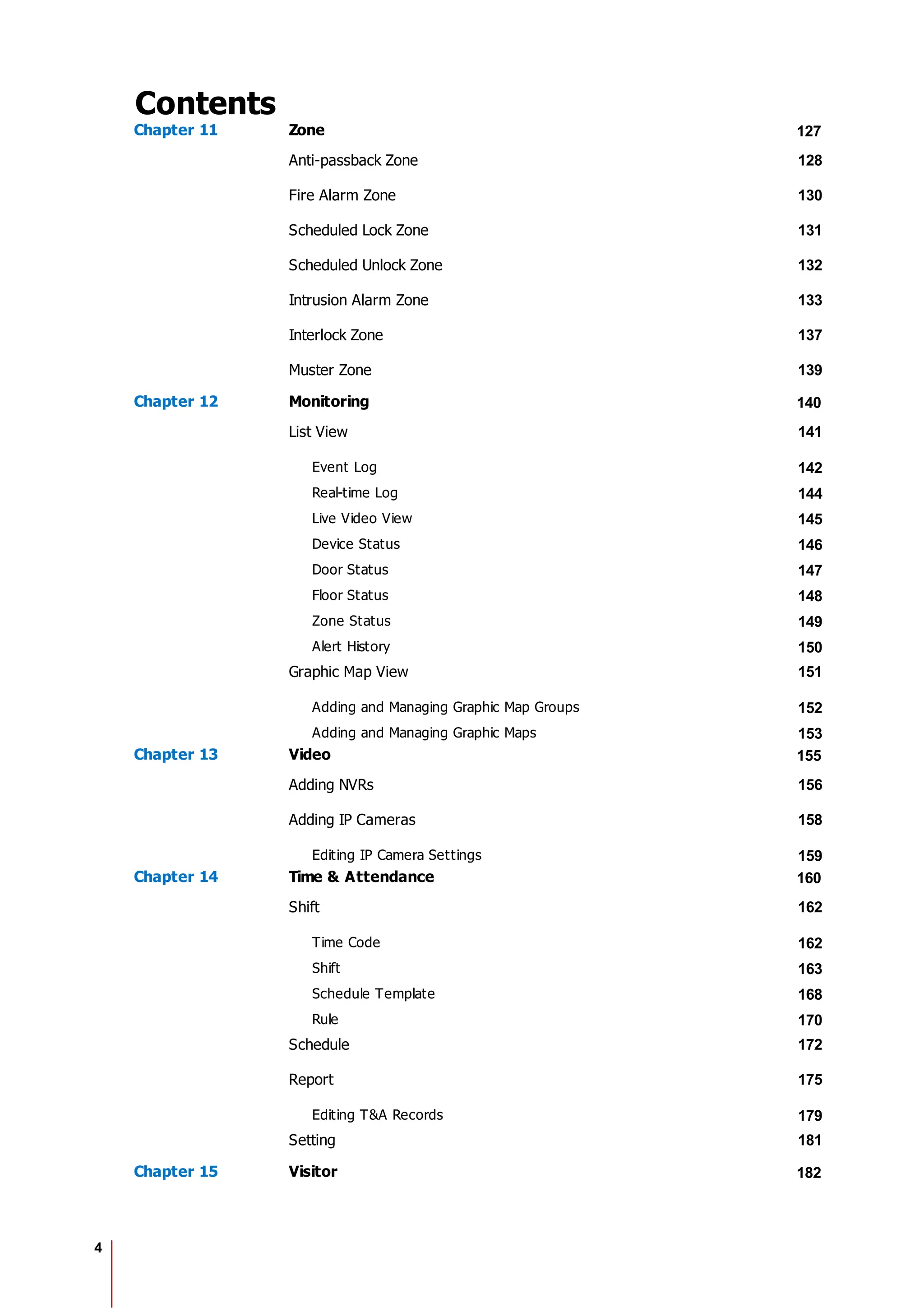
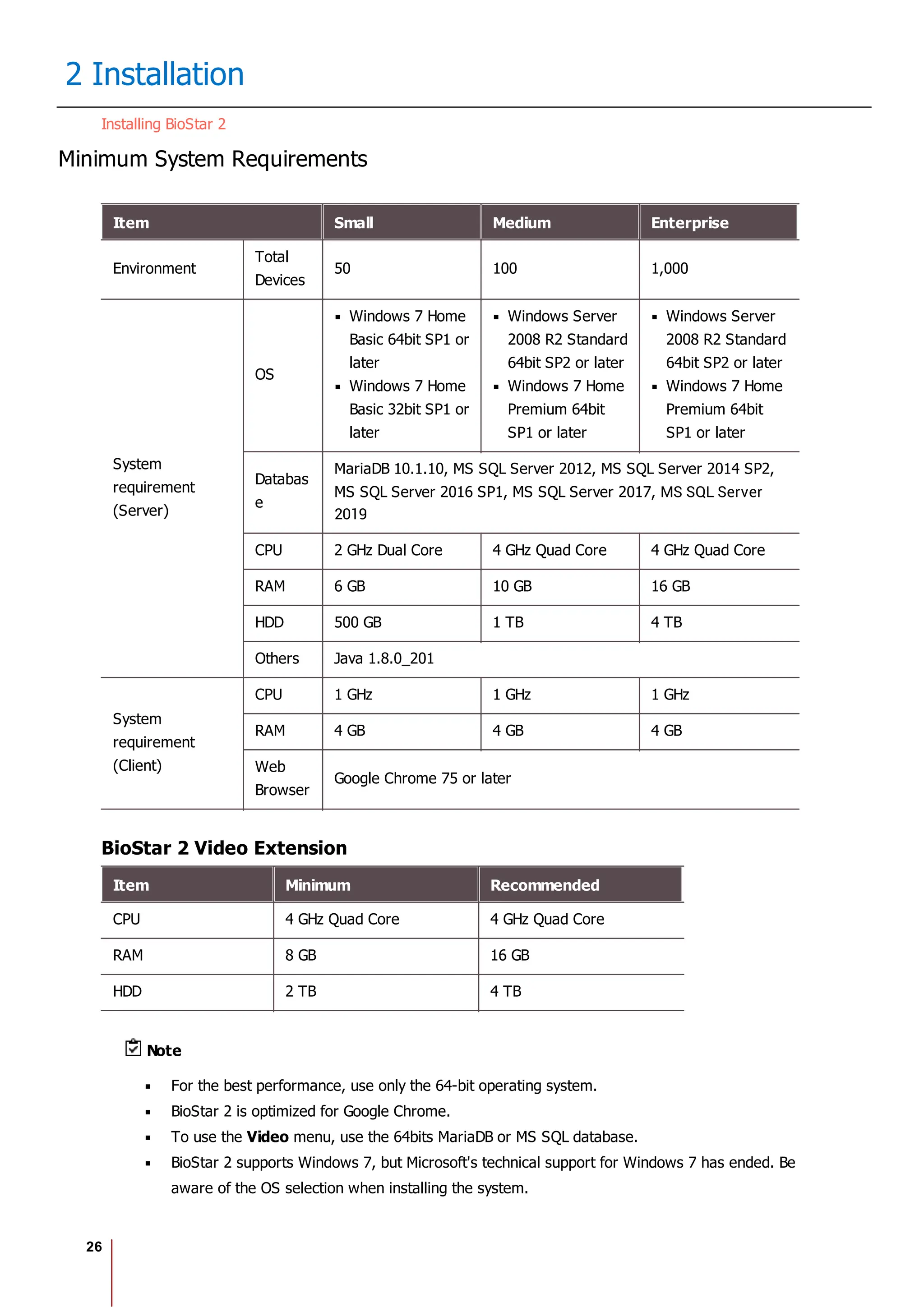
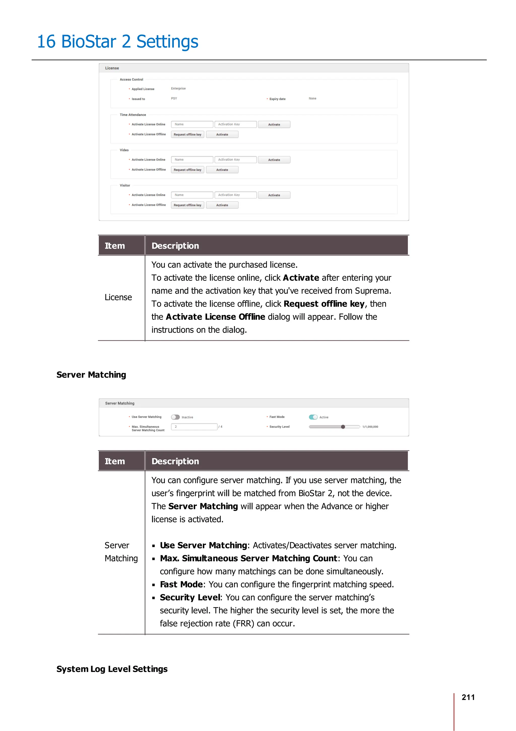
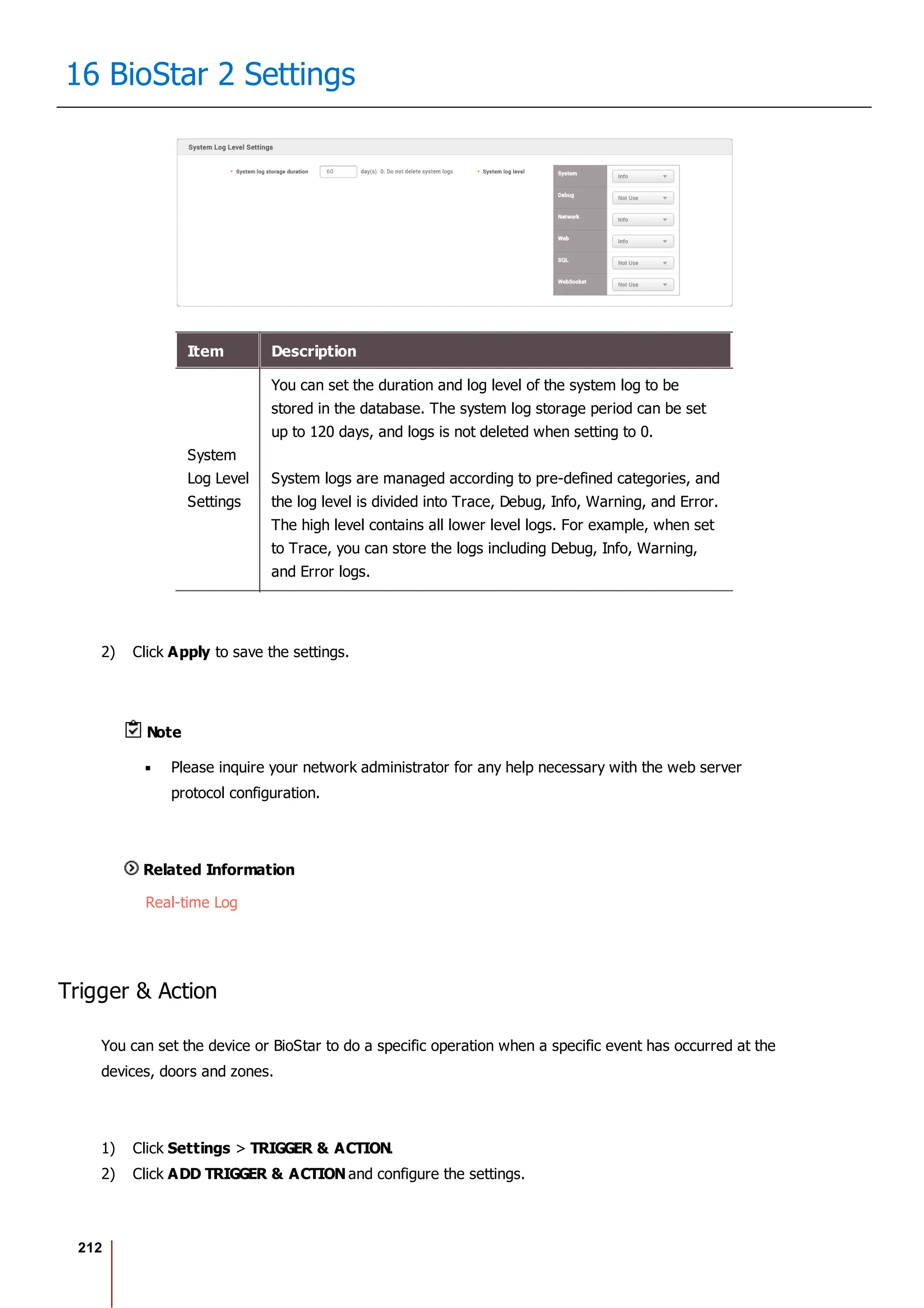
16 BioStar 2 Settings
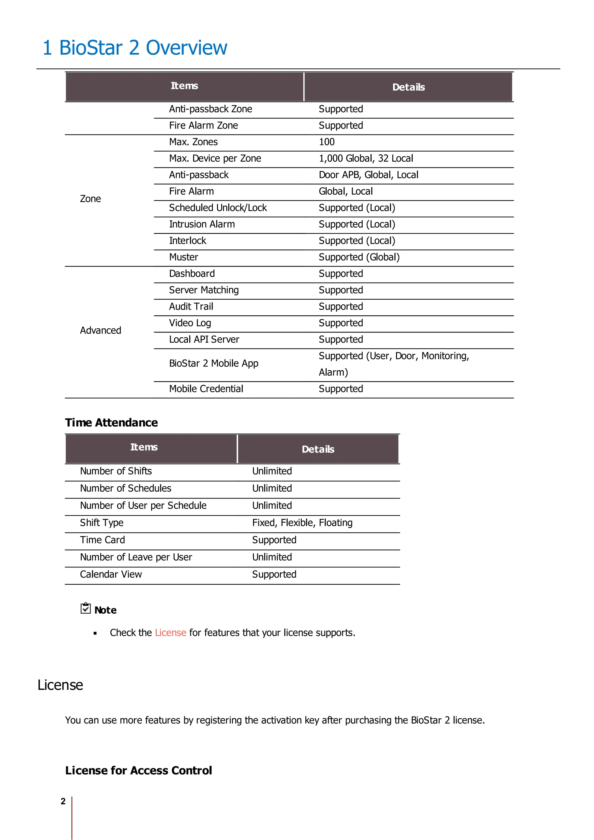
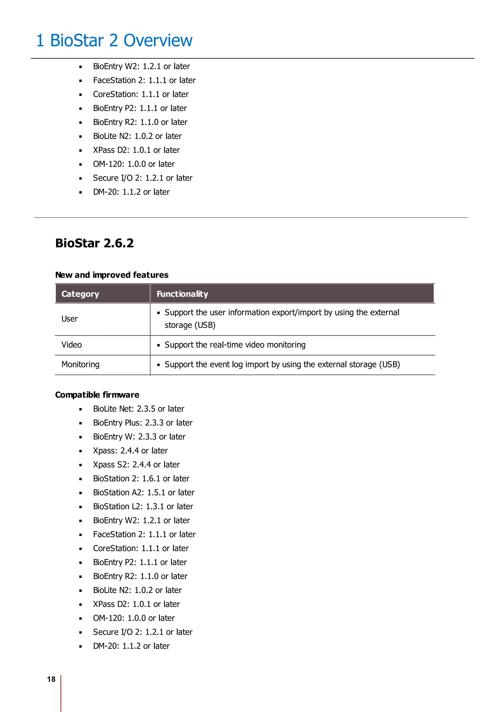
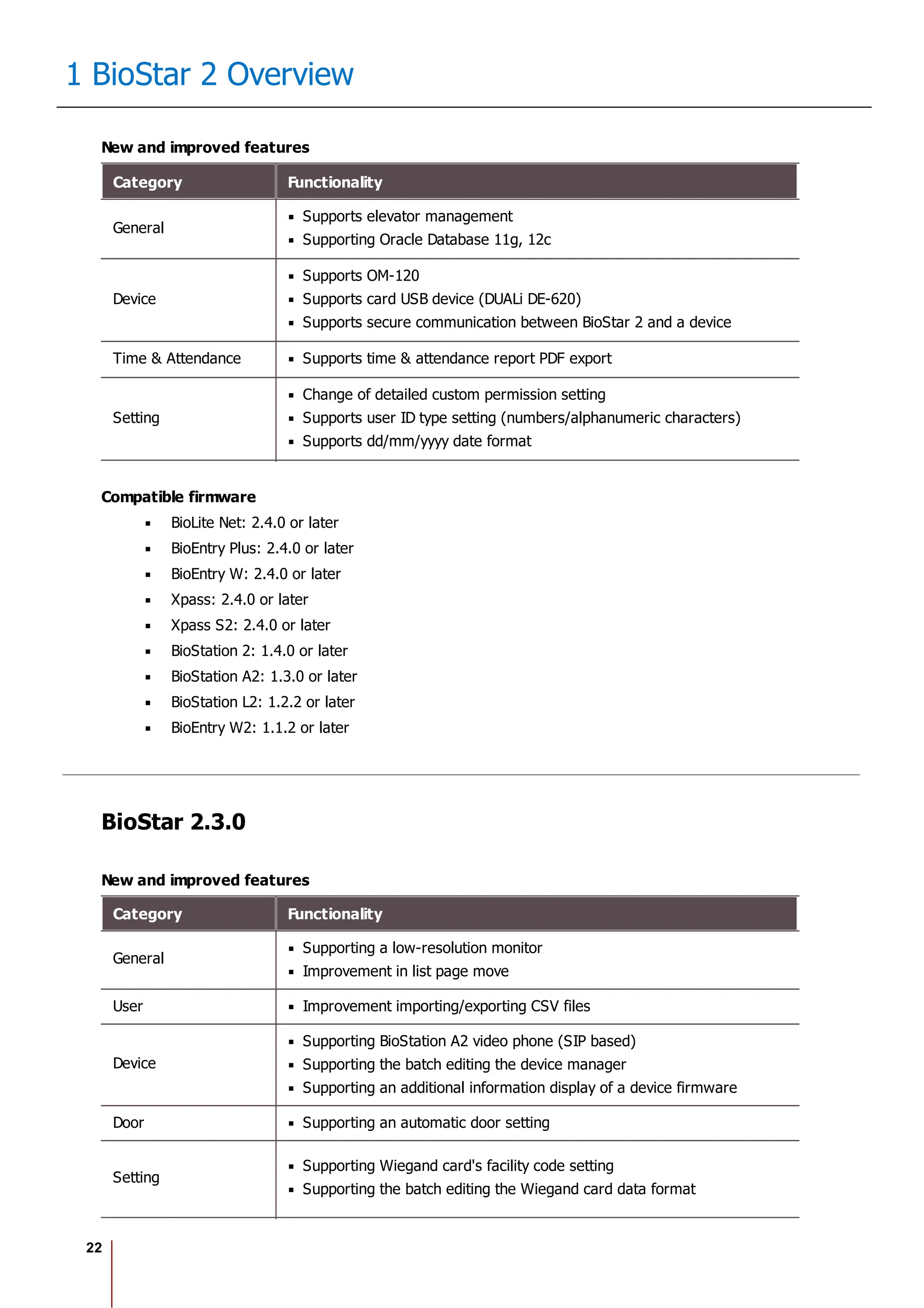
Item Description
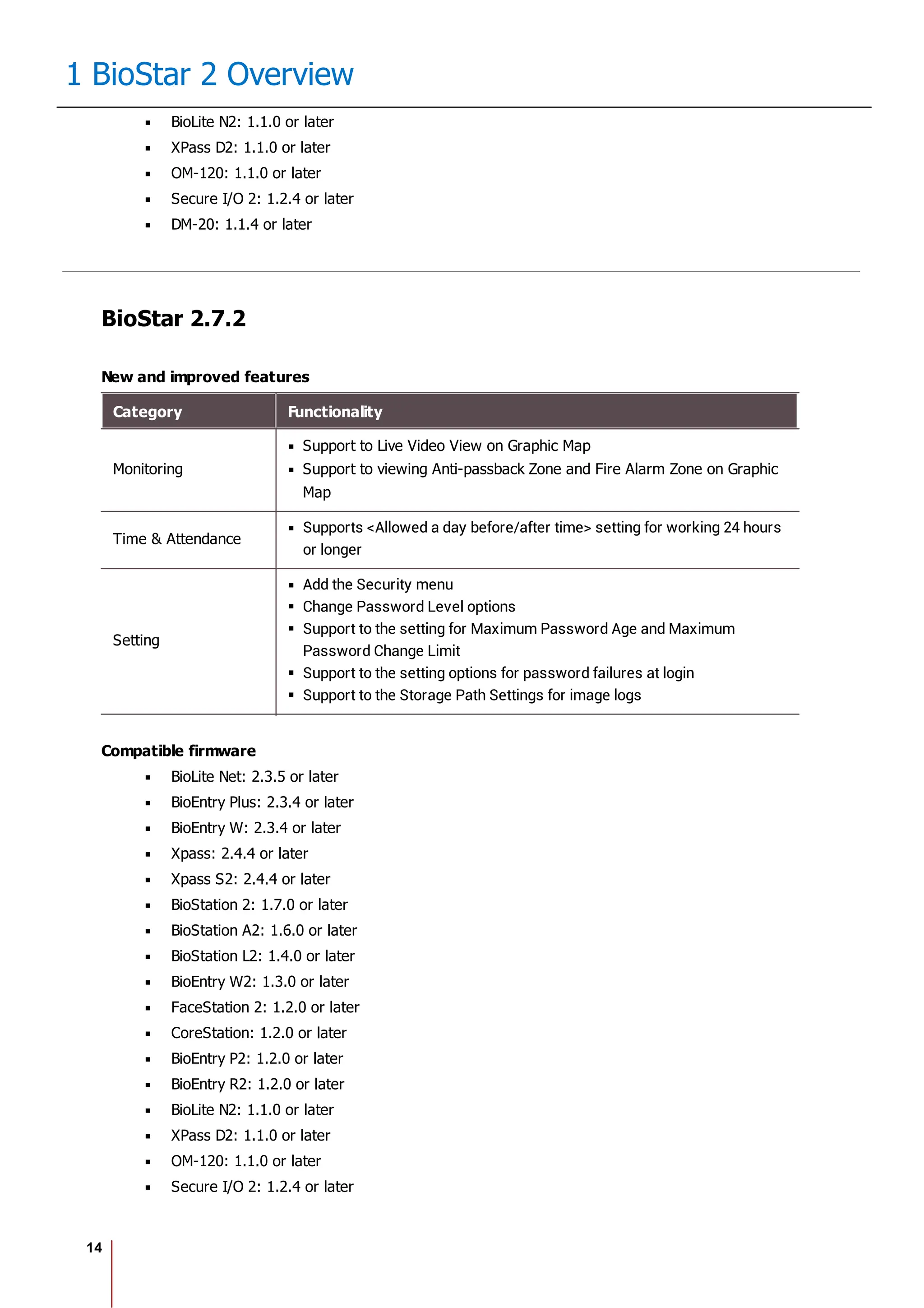
- BioStation L2 FW 1.3.0 or later
- BioLite N2 FW 1.0.0 or later
- BioEntry P2 FW 1.1.0 or later
- BioEntry W2 FW 1.2.0 or later
- FaceLite FW 1.0.0 or later
- XPass 2 FW 1.0.0 or later
- CoreStation FW 1.1.0 or later
BioStar 2 creates or deletes a certificate according
to the setting status of Secure communication
with device, and the same certificate as the
previous certificate will not be created. For
example, if the setting of Secure communication
with device is changed in the order of [Use - Not
Use], the created certificate will be deleted
automatically. When the setting is changed in the
order of [Use - Not Use - Use], the operation of
[Create A certificate - Delete A certificate - Create B
certificate] is carried out.
If the device is disconnected from the network
physically while using the secure communication of
BioStar 2, do not turn off the secure communication
option. In such a case, the certificate of BioStar 2
will be deleted, and the device will not be able to
connect again. To connect it again, the certificate
saved in the device must be deleted or the device
must be reset to factory default. For more details,
refer to the manual of the device.
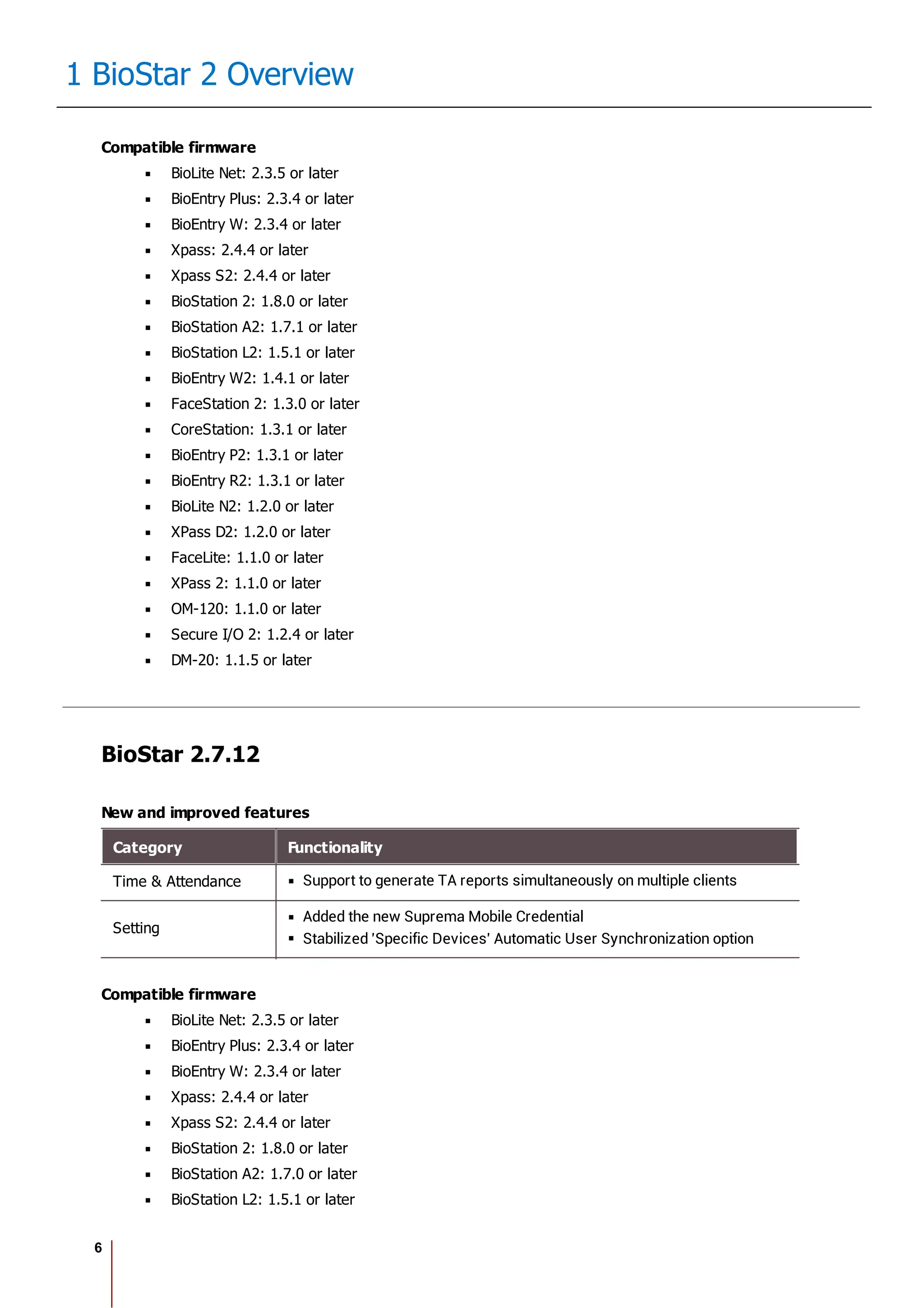
Session Security
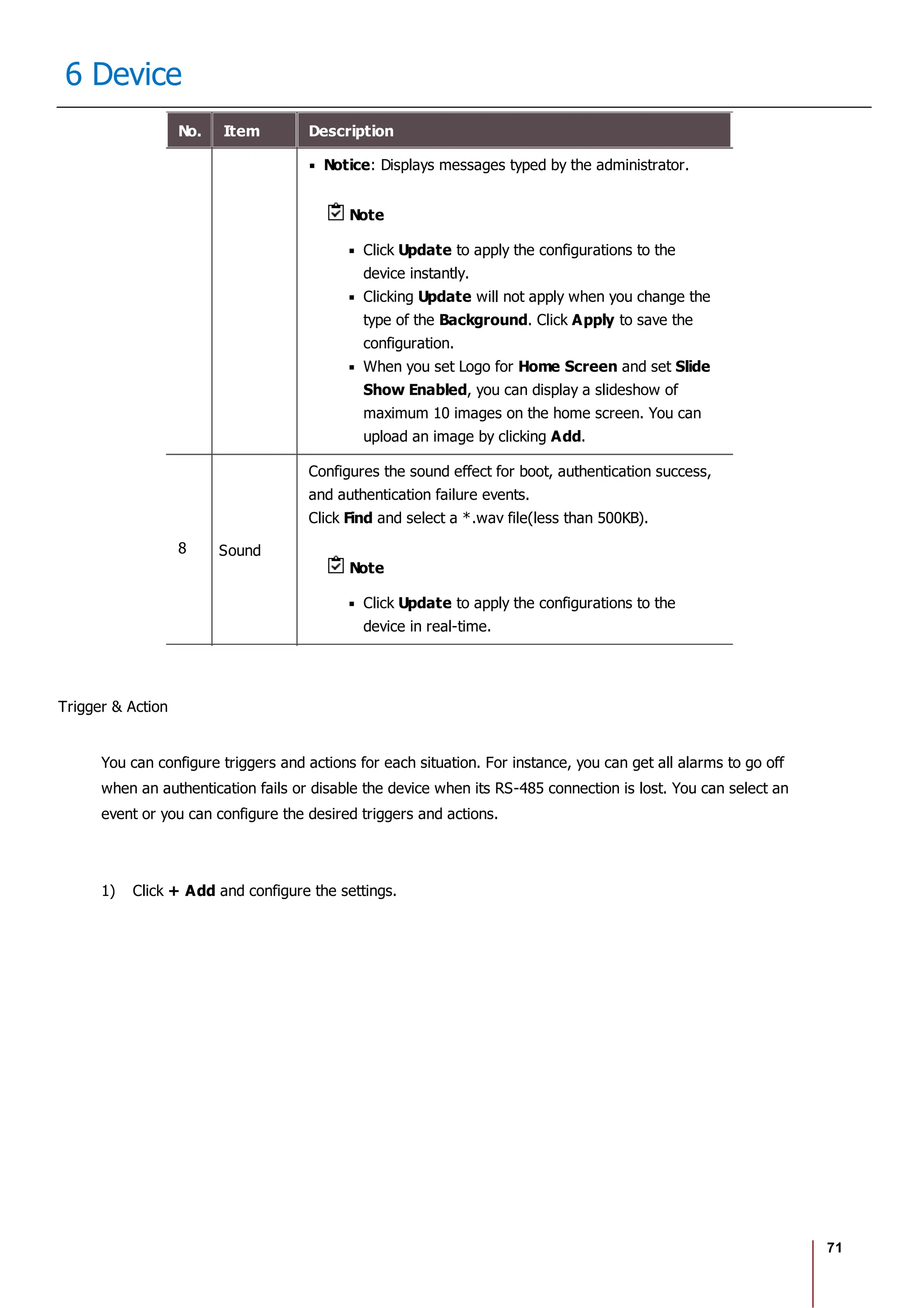
Item Description
Simultane
ous
Connectio
n Allow
You can set whether to allow simultaneous connections using the
same account. If you set Simultaneous Connection Allow to
Inactive, a previously logged in user will be logged out when
attempting to connect to the same account simultaneously.
3) Click Apply to save the settings.](https://image.slidesharecdn.com/biostar2administratorguidev1-240423133223-f59417ad/75/BioStar2_Administrator_Guide_V1-8-1_EN-pdf-234-2048.jpg)
![242
18 Appendix
problems of compatibility.
If you wish to obtain the latest specification documentation before you place an order for the
product, please contact Suprema, a sales agent of Suprema or a regional distributor.
Copyright Notice
Copyright of this documentation is reserved by Suprema. All other product names, trademarks,
registered trademarks are the property of their respective owners.
Open Source License
MariaDB LGPL client libraries for C and Java
The LGPL license
GNU LESSER GENERAL PUBLIC LICENSE
Version 2.1, February 1999
Copyright (C) 1991, 1999 Free Software Foundation, Inc.
51 Franklin Street, Fifth Floor, Boston, MA 02110-1301 USA
Everyone is permitted to copy and distribute verbatim copies
of this license document, but changing it is not allowed.
[This is the first released version of the Lesser GPL. It also counts
as the successor of the GNU Library Public License, version 2, hence
the version number 2.1.]
Preamble
The licenses for most software are designed to take away your freedom
to share and change it. By contrast, the GNU General Public Licenses
are intended to guarantee your freedom to share and change free
software--to make sure the software is free for all its users.
This license, the Lesser General Public License, applies to some
specially designated software packages--typically libraries--of the
Free Software Foundation and other authors who decide to use it. You
can use it too, but we suggest you first think carefully about whether
this license or the ordinary General Public License is the better
strategy to use in any particular case, based on the explanations](https://image.slidesharecdn.com/biostar2administratorguidev1-240423133223-f59417ad/75/BioStar2_Administrator_Guide_V1-8-1_EN-pdf-248-2048.jpg)

![272
18 Appendix
#
# THIS SOFTWARE IS PROVIDED BY THE COPYRIGHT HOLDERS AND
# CONTRIBUTORS "AS IS" AND ANY EXPRESS OR IMPLIED WARRANTIES,
# INCLUDING, BUT NOT LIMITED TO, THE IMPLIED WARRANTIES OF
# MERCHANTABILITY AND FITNESS FOR A PARTICULAR PURPOSE ARE
# DISCLAIMED. IN NO EVENT SHALL THE COPYRIGHT HOLDER OR CONTRIBUTORS
# BE LIABLE FOR ANY DIRECT, INDIRECT, INCIDENTAL, SPECIAL,
# EXEMPLARY, OR CONSEQUENTIAL DAMAGES (INCLUDING, BUT NOT LIMITED
# TO, PROCUREMENT OF SUBSTITUTE GOODS OR SERVICES; LOSS OF USE,
# DATA, OR PROFITS; OR BUSINESS INTERRUPTION) HOWEVER CAUSED AND ON
# ANY THEORY OF LIABILITY, WHETHER IN CONTRACT, STRICT LIABILITY, OR
# TORT (INCLUDING NEGLIGENCE OR OTHERWISE) ARISING IN ANY WAY OUT OF
# THE USE OF THIS SOFTWARE, EVEN IF ADVISED OF THE POSSIBILITY OF
# SUCH DAMAGE.
# --------------------------------------------------------------------------
5. Time Zone Database
ICU uses the public domain data and code derived from Time Zone
Database for its time zone support. The ownership of the TZ database
is explained in BCP 175: Procedure for Maintaining the Time Zone
Database section 7.
# 7. Database Ownership
#
# The TZ database itself is not an IETF Contribution or an IETF
# document. Rather it is a pre-existing and regularly updated work
# that is in the public domain, and is intended to remain in the
# public domain. Therefore, BCPs 78 [RFC5378] and 79 [RFC3979] do
# not apply to the TZ Database or contributions that individuals make
# to it. Should any claims be made and substantiated against the TZ
# Database, the organization that is providing the IANA
# Considerations defined in this RFC, under the memorandum of
# understanding with the IETF, currently ICANN, may act in accordance
# with all competent court orders. No ownership claims will be made
# by ICANN or the IETF Trust on the database or the code. Any person
# making a contribution to the database or code waives all rights to
# future claims in that contribution or in the TZ Database.
"""
- libuv, located at deps/uv, is licensed as follows:
"""
libuv is part of the Node project: http://nodejs.org/](https://image.slidesharecdn.com/biostar2administratorguidev1-240423133223-f59417ad/75/BioStar2_Administrator_Guide_V1-8-1_EN-pdf-278-2048.jpg)
![295
18 Appendix
* ANY EXPRESS OR IMPLIED WARRANTIES, INCLUDING, BUT NOT LIMITED TO, THE
* IMPLIED WARRANTIES OF MERCHANTABILITY AND FITNESS FOR A PARTICULAR PURPOSE
* ARE DISCLAIMED. IN NO EVENT SHALL THE AUTHOR OR CONTRIBUTORS BE LIABLE
* FOR ANY DIRECT, INDIRECT, INCIDENTAL, SPECIAL, EXEMPLARY, OR CONSEQUENTIAL
* DAMAGES (INCLUDING, BUT NOT LIMITED TO, PROCUREMENT OF SUBSTITUTE GOODS
* OR SERVICES; LOSS OF USE, DATA, OR PROFITS; OR BUSINESS INTERRUPTION)
* HOWEVER CAUSED AND ON ANY THEORY OF LIABILITY, WHETHER IN CONTRACT, STRICT
* LIABILITY, OR TORT (INCLUDING NEGLIGENCE OR OTHERWISE) ARISING IN ANY WAY
* OUT OF THE USE OF THIS SOFTWARE, EVEN IF ADVISED OF THE POSSIBILITY OF
* SUCH DAMAGE.
*
* The licence and distribution terms for any publically available version or
* derivative of this code cannot be changed. i.e. this code cannot simply be
* copied and put under another distribution licence
* [including the GNU Public Licence.]
*/
PCRE
PCRE LICENCE
------------
PCRE is a library of functions to support regular expressions whose syntax
and semantics are as close as possible to those of the Perl 5 language.
Release 8 of PCRE is distributed under the terms of the "BSD" licence, as
specified below. The documentation for PCRE, supplied in the "doc"
directory, is distributed under the same terms as the software itself.
The basic library functions are written in C and are freestanding. Also
included in the distribution is a set of C++ wrapper functions, and a
just-in-time compiler that can be used to optimize pattern matching. These
are both optional features that can be omitted when the library is built.
THE BASIC LIBRARY FUNCTIONS
---------------------------
Written by: Philip Hazel
Email local part: ph10
Email domain: cam.ac.uk](https://image.slidesharecdn.com/biostar2administratorguidev1-240423133223-f59417ad/75/BioStar2_Administrator_Guide_V1-8-1_EN-pdf-301-2048.jpg)
![303
18 Appendix
you a non-exclusive, non-transferable, revocable license to Execute (as defined herein) the executable
form of the Software on or in connection with hardware products sold by the Company, solely for your
internal business purposes. You may make a single copy of the Software for backup purposes, provided
that you reproduce on it all copyright and other proprietary notices that are on the original copy of the
Software. Company reserves all rights in the Software not expressly granted to you in this Agreement.
For purposes of this Agreement, “Execute” and “Execution” means to load, install, and run the Software
in order to benefit from its functionality as designed by Company.
2. Restrictions.
Except as expressly specified in this Agreement, you may not: (a) copy (except in the course of loading
or installing) or modify the Software, including but not limited to adding new features or otherwise
making adaptations that alter the functioning of the Software; (b) transfer, sublicense, lease, lend, rent
or otherwise distribute the Software to any third party; or (c) make the functionality of the Software
available to multiple users through any means, including but not limited to by uploading the Software to
a network or file-sharing service or through any hosting, application services provider, service bureau,
software-as-a-service (SaaS) or any other type of services. You acknowledge and agree that portions
of the Software, including but not limited to the source code and the specific design and structure of
individual modules or programs, constitute or contain trade secrets of Company and its licensors.
Accordingly, you agree not to disassemble, decompile or reverse engineer the Software, in whole or in
part, or permit or authorize a third party to do so, except to the extent such activities are expressly
permitted by law notwithstanding this prohibition.
3. Ownership.
The copy of the Software is licensed, not sold. You own the media on which the Software is recorded,
but Company retains ownership of the copy of the Software itself, including all intellectual property
rights therein. The Software is protected by copyright laws and the related regulations of your
jurisdictional countries, the copyright law of the Republic of Korea, and international treaties. You will
not delete or in any manner alter the copyright, trademark, and other proprietary rights notices or
markings appearing on the Software as delivered to you.
4. Term.
The license granted under this Agreement remains in effect for a period of 75 years, unless earlier
terminated in accordance with this Agreement. You may terminate the license at any time by destroying
all copies of the Software in your possession or control. The license granted under this Agreement will
automatically terminate, with or without notice from Company, if you breach any term of this
Agreement. Upon termination, you must at Company’s option either promptly destroy or return to
Company all copies of the Software in your possession or control.
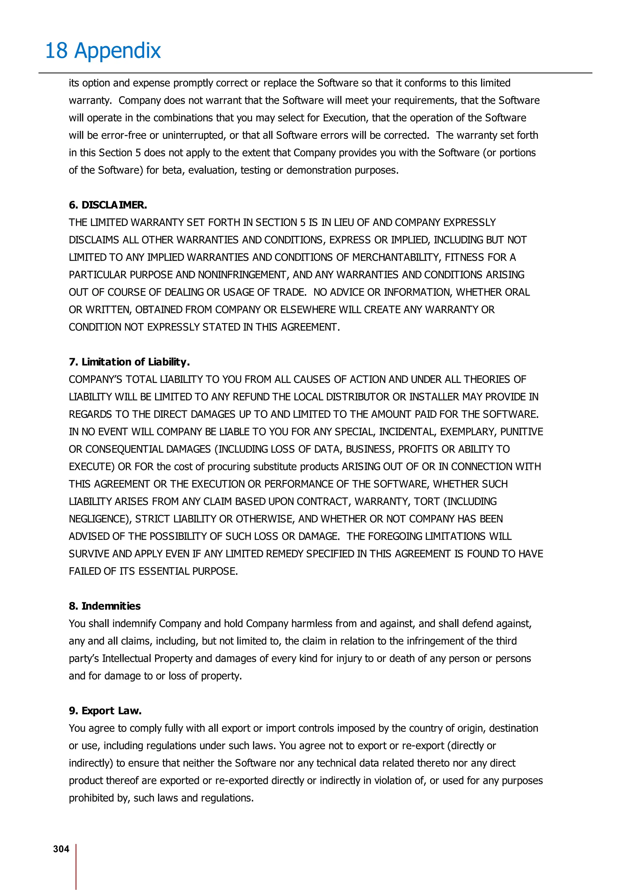
5. Limited Warranty.
Company warrants that, for [thirty (30)] days following the date of purchase (or delivery, if Company
has made the Software available to you without charge), the Software will perform in all material
respects in accordance with any accompanying documentation (“Documentation”). As your sole and
exclusive remedy and Company’s entire liability for any breach of this limited warranty, Company will at](https://image.slidesharecdn.com/biostar2administratorguidev1-240423133223-f59417ad/75/BioStar2_Administrator_Guide_V1-8-1_EN-pdf-309-2048.jpg)


The Biostar 2.8.1 Administrator Guide outlines the features and functionalities of Biostar 2, a web-based access control management system compatible with various devices and systems. It details installation procedures, user management, device integration, access control configurations, and troubleshooting guidelines. The document also includes information on the system's licensing, system requirements, and new features added in recent updates.


