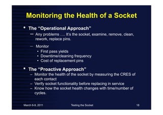
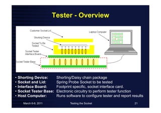
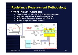
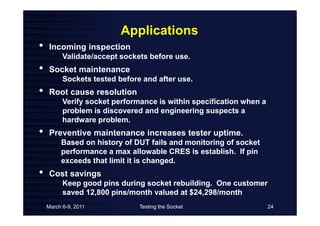
Testing the Socket
– The Benefits of Verifying Socket Functionality.


 Josef Magro*, Silvio Spiteri*, Marco Michi+,
    David Weston+ and James Forster+
         *St Micro    + WELLS-CTI
                2011 BiTS Workshop
                  March 6 - 9, 2011
Agenda

• Introduction and background
• Review Contact Resistance and it’s
  importance.
• Describe the CRES Tester
• Experience at ST Micro
• Closing comments


March 6-9, 2011   Testing the Socket   2
Introduction
•   For test or burn-in the contact resistance is one of
    the most important characteristics of a pin.
•   If the contact is the heart of a socket then contact
    resistance is pulse of the socket.
     – When it is low and stable the contact is healthy
         and in good shape.
     – When it is high and variable there is a problem.
•   What is contact resistance?
     – How do we measure it?
     – How do we monitor it?
•   This presentation will attempt to answer these
    questions.
March 6-9, 2011        Testing the Socket            3
Introduction

                           • What is a test socket?
                                  The single interface
                                  between a device being
                                  tested and a > $100K ATE
                    • An assembly of electrical
                      conductors in a non-
                      conductive body.
                    • How do you know the test
                      socket is “good”?

March 6-9, 2011     Testing the Socket                4
Introduction
•   There are many kinds of “contacts” or pins.
•   Fit into 3 broad categories
    – Stamped and formed.
    – Assembled springs and contact tips – e.g. spring or pogo
      pins
    – Others, elastomers and …


              Pictures of different contacts from past BiTS Presentations
March 6-9, 2011                  Testing the Socket                         5
Introduction
    – Assembled springs and contact tips – e.g. spring or pogo
       pins


                  From New Development in High Temperature
                  pring Probes, Winter et al BiTS 2010


              Pictures of different pins from past BiTS Presentations
March 6-9, 2011                  Testing the Socket                     6
Introduction
•   Key electrical characteristic is contact resistance.
•   Contact resistance can be inconsistent and “messy”.
•   It can be effected by lead finish, plating, temperature,
    number of cycles


From “Automated Burn-in Socket Testing and        From “Contacting Pb-free finishes – A study of the effects
      Evaluation,” Hoppe, BiTS Workshop 2003            of different lead finishes on the CRES and
                                                        Reliability of a QFP contact”, Forster et al, BiTS
                                                        Workshop 2009

March 6-9, 2011                        Testing the Socket                                        7
Introduction
     •    The causes of variation ….. contamination, wear
          and plating failures have been documented by
          many….


From “Test on Ball,” Elmadbouly, BiTS
      Workshop 2009

                                        From “An Examination of the Causes of
                                              Cres Degradation …..,” Langston,
                                              BiTS Workshop 2008


                                                                                 From “Application of Socket Cleaning …,”
                                                                                       Orwoll, BiTS Workshop 2005
     March 6-9, 2011                            Testing the Socket                                               8
What is Contact Resistance?
•   The sum of all the resistances associated with
    interfaces and the bulk resistance of a contact.
•   The “Contact Resistance” of a contact is shown in
    the schematic for a BGA and includes:

                         1. The “constriction resistance” of the
                            interface between the pad on the test
                            board and the contact
                         2. The bulk resistance of the contact
                         3. The “constriction resistance” of the
                            interface between the solder ball on
                            the package and the contact.


March 6-9, 2011       Testing the Socket                    9
What is Constriction Resistance?
•   The bulk resistance of the contact is dependent on
    material resistivity. Copper is better than steel
•   The constriction resistance is the resistance
    between two surfaces because they only touch at a
    few points
                                               Constriction resistance
             Current
             flow lines
             in body of
             contact
                          Surface
                          film


                               Contact asperities         High current density

                                                 From “Electric Contacts” by Holm

March 6-9, 2011           Testing the Socket                                        10
What is Constriction Resistance?
•   When 2 surfaces touch the surface film is disrupted and with
    sufficient force or wiping the metal surfaces come into contact and a
    small area of intimate metal-to-metal contact is formed.
•   It is important to differentiate between two surfaces touching and an
    “Ohmic contact”.
•   An Ohmic contact is one where the current and voltage follow a
    linear relationship i.e Ohm’s law holds V=IR


                                                         Contact

                                    Air                                 Film

                                                         Pad

                                                               Non conductive
                                                               films touching

                                  Ohmic contact          Metal to metal contact
                                  Current flows freely   but not conductive
     March 6-9, 2011           Testing the Socket                                 11
Problems at Test
 •   When a new device gets to production there is an
     expected yield but when that yield drops what
     are the causes?
 •   Possible causes of poor yield
      – Defective devices
           • Issues on the silicon from manufacturing
      – Package problems
              Missing balls              Package size
      – Handler issues
                  Jams                   Worn out or broken parts
      – Socket reliability
                  Contact CRES                        Contact force

March 6-9, 2011                  Testing the Socket                   12
So What and Who Cares?
 •   Contacts touch                Current flows
 •   Major property controlling this is contact
     resistance CRES
 •   Why should I care about the CRES?
         ……..Because in the end it’s all about costs


 •   Since I care about costs I care about the CRES –
     but how can I measure it?

March 6-9, 2011        Testing the Socket              13
The Impact of CRES
•   First Pass Yield.
     – A good set-up would:-
        • Reliably and definitively identify good devices.
        • There would be no miss-tests or marginal fails.


• First Pass Yield is often used as an indicator of
    socket performance.
    – There is an expected yield, when
      that drops the performance and
      reliability of the socket is suspect
    – Monitoring first pass yield can be
      used to compare performance of
      suppliers, contacts or contact
      technology

    March 6-9, 2011             Testing the Socket           14
The Impact of CRES
•       Unstable/Inconsistent CRES or pin performance results in
        downtime and lost productivity due to:-
         – Retest
         – Troubleshooting
         – Maintenance
         – Cleaning
         – Identification of “bad” pins
         – Pin replacement
    •     Reliable pin performance, even
          at significantly higher prices,
          pays dividends in:-
           – Capacity improvements
           – Availability of staff to
              concentrate on production.


        March 6-9, 2011           Testing the Socket               15
The Impact of CRES
                        • Lets take a look at the two sockets
                          shown in the previous slide.
                           – A good set-up would reliably and definitively
                             identify good devices.
                           – Customer evaluated 2 sockets
                           – Number of devices tested approx. 300K/socket
                                                            Socket A   Socket B
                                        1st Pass Yield        X%        X+5%
                                        Final                 Y%         Y%
                                        Socket Cost ($)       1X         3X
                                        Pin Cost ($)          1X         2.5X
                                        Retest Costs ($)      3X          X
                                        Downtime (hrs)       More         −
                                        Pin Life (Cycles)    Less         −
Total cost savings over life of project using socket B estimated >$250K
     March 6-9, 2011             Testing the Socket                        16
Benefits of a Reliable Socket
•    Receive full entitlement for the investment
      – Reduced operational costs
      – Delay capital investments by eliminating the hidden
        factory
          • Capacity used in rework/retest
          • Lost time due to downtime associated with socket
            cleaning and replacement
•    Socket purchase decisions based on cost of
     ownership, not acquisition cost
•    But how can you evaluate the life/health of a socket?

    March 6-9, 2011       Testing the Socket              17
Monitoring the Health of a Socket
•   The “Operational Approach”
     –   Any problems …. It’s the socket, examine, remove, clean,
         rework, replace pins.
     –   Monitor
         • First pass yields
         • Downtime/cleaning frequency
         • Cost of replacement pins

•   The “Proactive Approach”
     – Monitor the health of the socket by measuring the CRES of
       each contact
     – Verify socket functionality before replacing in service
     – Know how the socket health changes with time/number of
       cycles.


March 6-9, 2011              Testing the Socket                     18
Socket Contact Resistance Tester
•    The CR-2600 tester is:-
            – portable,
            – easy to use
•    Validates socket integrity by measuring contact resistance.
•    Identifies the locations of open or high resistance pins within a
     socket array.
•    User interface is displayed on a
     Windows computer via USB
     connection.
•    No standard maintenance is
     required.
•    Self calibrates before each
     measurement using 8 internal
     precision resistors for
     reference.
•    Makes a Kelvin measurement.
    March 6-9, 2011            Testing the Socket                  19
Key Components


March 6-9, 2011       Testing the Socket   20
Tester - Overview


•   Shorting Device:      Shorting/Daisy chain package
•   Socket and Lid:       Spring Probe Socket to be tested
•   Interface Board:      Footprint specific, socket interface card.
•   Socket Tester Base:   Electronic circuitry to perform tester function
•   Host Computer:        Runs software to configure tester and report results
      March 6-9, 2011             Testing the Socket                    21
Resistance Measurement Methodology
• 4-Wire (Kelvin) Approach
      –   Eliminates PCB and Cabling From Measurement
      –   Requires Separate Current & Voltage Path
      –   Accurately measures low-valued resistors
      –   Allows single pin measurement


  March 6-9, 2011          Testing the Socket           22
Overview CR-2600 Tester
•    Solution includes
        − Software interface for ease of operation

        − Test probe pen

        − Interface boards

        − Custom built daisy chain and shorting
            packages


•    For a more detailed description of the tester
     see unit at the WELLS booth.
    March 6-9, 2011          Testing the Socket      23
Applications
•    Incoming inspection
          Validate/accept sockets before use.
•    Socket maintenance
          Sockets tested before and after use.
•    Root cause resolution
          Verify socket performance is within specification when a
          problem is discovered and engineering suspects a
          hardware problem.
•    Preventive maintenance increases tester uptime.
         Based on history of DUT fails and monitoring of socket
         performance a max allowable CRES is establish. If pin
         exceeds that limit it is changed.
•    Cost savings
          Keep good pins during socket rebuilding. One customer
          saved 12,800 pins/month valued at $24,298/month
    March 6-9, 2011            Testing the Socket                    24
ST Micro - Experience
•    PROBLEM: Test Contact Issues.
      – Downtime due to test contact issues.
      – No verification of the socket refurbishing process
        effectiveness.
      – Typical device 35x35mmPBGA with 680 balls


•    ACTION:
      – Introduced the use of a socket tester to check
        pogo pin resistance after cleaning

    March 6-9, 2011          Testing the Socket          25
ST Micro - Experience
• Introduced the use of a socket tester


 March 6-9, 2011          Testing the Socket   26
ST Micro - Experience
•   The socket tester helps the technician identify failing
    pins more easily and quickly.
     – Improves the OEE, Overall Equipment Efficiency
     – Reduces the pogo pin consumption


User-friendly software
highlighting the failing
pin.

Green: Resistance < 0.8 Ohms
Red: Resistance > 0.8 Ohms
Black: No contact.
The threshold (0.8)can be changed.
    March 6-9, 2011          Testing the Socket         27
ST Micro - Experience
•   Pogo Pin Consumption.
     – Reduced more than 35%


March 6-9, 2011          Testing the Socket   28
ST Micro - Experience
• Socket Tester Enabled:
   –   Faulty Pogo Pins to be easily identified
   –   Faster repair
   –   Reduced socket maintenance costs
   –   Reduced pogo pins consumption, only replaced
       those pins with high CRES
• Production Benefit
   – Only good sockets are supplied to the production
     test floor
   – Reduced setup time
   – Reduced re-tests
   – More tester up-time
 March 6-9, 2011          Testing the Socket       29
Closing Comments

•   We are learning more about the pin.
•   Simplified identification of pin failures.
•   Being able to easily and efficiently measure the pin
    CRES has led to improvements in the
    understanding of pin reliability, appropriate
    cleaning intervals and the effectiveness of cleaning
•   Overall costs have been reduced by reducing
    downtime and expenditures for pins; the overall test
    floor equipment efficiency has been increased.


March 6-9, 2011          Testing the Socket          30

Testing the Socket - The Benefits of Verifying Socket Functionality

  • 1.
    Testing the Socket –The Benefits of Verifying Socket Functionality. Josef Magro*, Silvio Spiteri*, Marco Michi+, David Weston+ and James Forster+ *St Micro + WELLS-CTI 2011 BiTS Workshop March 6 - 9, 2011
  • 2.
    Agenda • Introduction andbackground • Review Contact Resistance and it’s importance. • Describe the CRES Tester • Experience at ST Micro • Closing comments March 6-9, 2011 Testing the Socket 2
  • 3.
    Introduction • For test or burn-in the contact resistance is one of the most important characteristics of a pin. • If the contact is the heart of a socket then contact resistance is pulse of the socket. – When it is low and stable the contact is healthy and in good shape. – When it is high and variable there is a problem. • What is contact resistance? – How do we measure it? – How do we monitor it? • This presentation will attempt to answer these questions. March 6-9, 2011 Testing the Socket 3
  • 4.
    Introduction • What is a test socket? The single interface between a device being tested and a > $100K ATE • An assembly of electrical conductors in a non- conductive body. • How do you know the test socket is “good”? March 6-9, 2011 Testing the Socket 4
  • 5.
    Introduction • There are many kinds of “contacts” or pins. • Fit into 3 broad categories – Stamped and formed. – Assembled springs and contact tips – e.g. spring or pogo pins – Others, elastomers and … Pictures of different contacts from past BiTS Presentations March 6-9, 2011 Testing the Socket 5
  • 6.
    Introduction – Assembled springs and contact tips – e.g. spring or pogo pins From New Development in High Temperature pring Probes, Winter et al BiTS 2010 Pictures of different pins from past BiTS Presentations March 6-9, 2011 Testing the Socket 6
  • 7.
    Introduction • Key electrical characteristic is contact resistance. • Contact resistance can be inconsistent and “messy”. • It can be effected by lead finish, plating, temperature, number of cycles From “Automated Burn-in Socket Testing and From “Contacting Pb-free finishes – A study of the effects Evaluation,” Hoppe, BiTS Workshop 2003 of different lead finishes on the CRES and Reliability of a QFP contact”, Forster et al, BiTS Workshop 2009 March 6-9, 2011 Testing the Socket 7
  • 8.
    Introduction • The causes of variation ….. contamination, wear and plating failures have been documented by many…. From “Test on Ball,” Elmadbouly, BiTS Workshop 2009 From “An Examination of the Causes of Cres Degradation …..,” Langston, BiTS Workshop 2008 From “Application of Socket Cleaning …,” Orwoll, BiTS Workshop 2005 March 6-9, 2011 Testing the Socket 8
  • 9.
    What is ContactResistance? • The sum of all the resistances associated with interfaces and the bulk resistance of a contact. • The “Contact Resistance” of a contact is shown in the schematic for a BGA and includes: 1. The “constriction resistance” of the interface between the pad on the test board and the contact 2. The bulk resistance of the contact 3. The “constriction resistance” of the interface between the solder ball on the package and the contact. March 6-9, 2011 Testing the Socket 9
  • 10.
    What is ConstrictionResistance? • The bulk resistance of the contact is dependent on material resistivity. Copper is better than steel • The constriction resistance is the resistance between two surfaces because they only touch at a few points Constriction resistance Current flow lines in body of contact Surface film Contact asperities High current density From “Electric Contacts” by Holm March 6-9, 2011 Testing the Socket 10
  • 11.
    What is ConstrictionResistance? • When 2 surfaces touch the surface film is disrupted and with sufficient force or wiping the metal surfaces come into contact and a small area of intimate metal-to-metal contact is formed. • It is important to differentiate between two surfaces touching and an “Ohmic contact”. • An Ohmic contact is one where the current and voltage follow a linear relationship i.e Ohm’s law holds V=IR Contact Air Film Pad Non conductive films touching Ohmic contact Metal to metal contact Current flows freely but not conductive March 6-9, 2011 Testing the Socket 11
  • 12.
    Problems at Test • When a new device gets to production there is an expected yield but when that yield drops what are the causes? • Possible causes of poor yield – Defective devices • Issues on the silicon from manufacturing – Package problems Missing balls Package size – Handler issues Jams Worn out or broken parts – Socket reliability Contact CRES Contact force March 6-9, 2011 Testing the Socket 12
  • 13.
    So What andWho Cares? • Contacts touch Current flows • Major property controlling this is contact resistance CRES • Why should I care about the CRES? ……..Because in the end it’s all about costs • Since I care about costs I care about the CRES – but how can I measure it? March 6-9, 2011 Testing the Socket 13
  • 14.
    The Impact ofCRES • First Pass Yield. – A good set-up would:- • Reliably and definitively identify good devices. • There would be no miss-tests or marginal fails. • First Pass Yield is often used as an indicator of socket performance. – There is an expected yield, when that drops the performance and reliability of the socket is suspect – Monitoring first pass yield can be used to compare performance of suppliers, contacts or contact technology March 6-9, 2011 Testing the Socket 14
  • 15.
    The Impact ofCRES • Unstable/Inconsistent CRES or pin performance results in downtime and lost productivity due to:- – Retest – Troubleshooting – Maintenance – Cleaning – Identification of “bad” pins – Pin replacement • Reliable pin performance, even at significantly higher prices, pays dividends in:- – Capacity improvements – Availability of staff to concentrate on production. March 6-9, 2011 Testing the Socket 15
  • 16.
    The Impact ofCRES • Lets take a look at the two sockets shown in the previous slide. – A good set-up would reliably and definitively identify good devices. – Customer evaluated 2 sockets – Number of devices tested approx. 300K/socket Socket A Socket B 1st Pass Yield X% X+5% Final Y% Y% Socket Cost ($) 1X 3X Pin Cost ($) 1X 2.5X Retest Costs ($) 3X X Downtime (hrs) More − Pin Life (Cycles) Less − Total cost savings over life of project using socket B estimated >$250K March 6-9, 2011 Testing the Socket 16
  • 17.
    Benefits of aReliable Socket • Receive full entitlement for the investment – Reduced operational costs – Delay capital investments by eliminating the hidden factory • Capacity used in rework/retest • Lost time due to downtime associated with socket cleaning and replacement • Socket purchase decisions based on cost of ownership, not acquisition cost • But how can you evaluate the life/health of a socket? March 6-9, 2011 Testing the Socket 17
  • 18.
    Monitoring the Healthof a Socket • The “Operational Approach” – Any problems …. It’s the socket, examine, remove, clean, rework, replace pins. – Monitor • First pass yields • Downtime/cleaning frequency • Cost of replacement pins • The “Proactive Approach” – Monitor the health of the socket by measuring the CRES of each contact – Verify socket functionality before replacing in service – Know how the socket health changes with time/number of cycles. March 6-9, 2011 Testing the Socket 18
  • 19.
    Socket Contact ResistanceTester • The CR-2600 tester is:- – portable, – easy to use • Validates socket integrity by measuring contact resistance. • Identifies the locations of open or high resistance pins within a socket array. • User interface is displayed on a Windows computer via USB connection. • No standard maintenance is required. • Self calibrates before each measurement using 8 internal precision resistors for reference. • Makes a Kelvin measurement. March 6-9, 2011 Testing the Socket 19
  • 20.
    Key Components March 6-9,2011 Testing the Socket 20
  • 21.
    Tester - Overview • Shorting Device: Shorting/Daisy chain package • Socket and Lid: Spring Probe Socket to be tested • Interface Board: Footprint specific, socket interface card. • Socket Tester Base: Electronic circuitry to perform tester function • Host Computer: Runs software to configure tester and report results March 6-9, 2011 Testing the Socket 21
  • 22.
    Resistance Measurement Methodology •4-Wire (Kelvin) Approach – Eliminates PCB and Cabling From Measurement – Requires Separate Current & Voltage Path – Accurately measures low-valued resistors – Allows single pin measurement March 6-9, 2011 Testing the Socket 22
  • 23.
    Overview CR-2600 Tester • Solution includes − Software interface for ease of operation − Test probe pen − Interface boards − Custom built daisy chain and shorting packages • For a more detailed description of the tester see unit at the WELLS booth. March 6-9, 2011 Testing the Socket 23
  • 24.
    Applications • Incoming inspection Validate/accept sockets before use. • Socket maintenance Sockets tested before and after use. • Root cause resolution Verify socket performance is within specification when a problem is discovered and engineering suspects a hardware problem. • Preventive maintenance increases tester uptime. Based on history of DUT fails and monitoring of socket performance a max allowable CRES is establish. If pin exceeds that limit it is changed. • Cost savings Keep good pins during socket rebuilding. One customer saved 12,800 pins/month valued at $24,298/month March 6-9, 2011 Testing the Socket 24
  • 25.
    ST Micro -Experience • PROBLEM: Test Contact Issues. – Downtime due to test contact issues. – No verification of the socket refurbishing process effectiveness. – Typical device 35x35mmPBGA with 680 balls • ACTION: – Introduced the use of a socket tester to check pogo pin resistance after cleaning March 6-9, 2011 Testing the Socket 25
  • 26.
    ST Micro -Experience • Introduced the use of a socket tester March 6-9, 2011 Testing the Socket 26
  • 27.
    ST Micro -Experience • The socket tester helps the technician identify failing pins more easily and quickly. – Improves the OEE, Overall Equipment Efficiency – Reduces the pogo pin consumption User-friendly software highlighting the failing pin. Green: Resistance < 0.8 Ohms Red: Resistance > 0.8 Ohms Black: No contact. The threshold (0.8)can be changed. March 6-9, 2011 Testing the Socket 27
  • 28.
    ST Micro -Experience • Pogo Pin Consumption. – Reduced more than 35% March 6-9, 2011 Testing the Socket 28
  • 29.
    ST Micro -Experience • Socket Tester Enabled: – Faulty Pogo Pins to be easily identified – Faster repair – Reduced socket maintenance costs – Reduced pogo pins consumption, only replaced those pins with high CRES • Production Benefit – Only good sockets are supplied to the production test floor – Reduced setup time – Reduced re-tests – More tester up-time March 6-9, 2011 Testing the Socket 29
  • 30.
    Closing Comments • We are learning more about the pin. • Simplified identification of pin failures. • Being able to easily and efficiently measure the pin CRES has led to improvements in the understanding of pin reliability, appropriate cleaning intervals and the effectiveness of cleaning • Overall costs have been reduced by reducing downtime and expenditures for pins; the overall test floor equipment efficiency has been increased. March 6-9, 2011 Testing the Socket 30