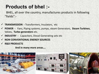
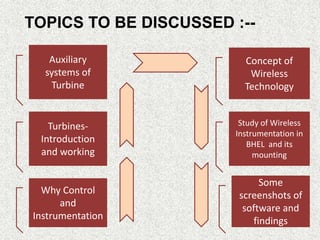
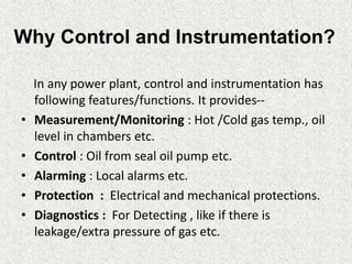
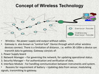
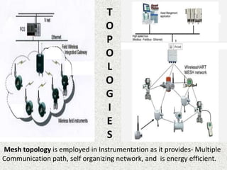
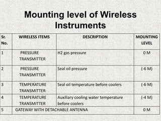
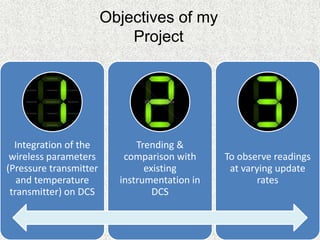
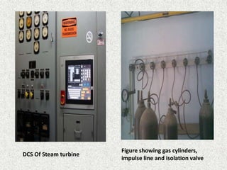
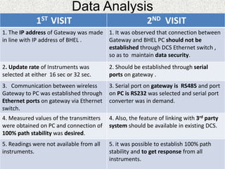
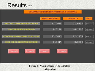
2. Stands for Bharat Heavy
Electricals Limited. It was
established in 1956, and one of
the major PSU’s in India.
It is :
One of India’s top Navratan
companies.
among one of the top 10
manufacturing organizations of
power generating equipments
in the world.
Has highly skilled and committed
workforce of over 49,000
employees, as its greatest
strength.
My Training @ BHEL Haridwar
(View of chimneys in power plant)
3. Products of bhel :-
BHEL, all over the country, manufactures products in following
“fields”:-
TRANSMISSION - Transformers, Insulators, etc
POWER - Fans, Piping systems, pumps, steam Generators, Steam Turbines,
Valves, Turbo generators etc.
INDUSTRY - Capacitors, Diesel Generating sets etc
NON CONVENTIONAL ENERGY SOURCES
R&D PRODUCTS
And in many more areas….
4. Auxiliary
systems of
Turbine
Concept of
Wireless
Technology
Why Control
and
Instrumentation
Turbines-
Introduction
and working
Some
screenshots of
software and
findings
Study of Wireless
Instrumentation in
BHEL and its
mounting
TOPICS TO BE DISCUSSED :--
5. Why Control and Instrumentation?
In any power plant, control and instrumentation has
following features/functions. It provides--
• Measurement/Monitoring : Hot /Cold gas temp., oil
level in chambers etc.
• Control : Oil from seal oil pump etc.
• Alarming : Local alarms etc.
• Protection : Electrical and mechanical protections.
• Diagnostics : For Detecting , like if there is
leakage/extra pressure of gas etc.
6. TURBINES : Introduction, Working and its
Auxiliary Systems
WHAT ? A rotary mechanical device that extracts energy from
fluid flow and converts it into useful work (electricity) . A turbine is a
turbo machine, with one moving part called ROTOR assembly, which
is a Shaft or Drum with “BLADES” attached. It has a STATOR too,
which is the STATIONARY part of the machine.
Fig: TG Sets
(Showing
Blades and
stator)
7. View of TG Set kept in Block 1 of
BHEL
Bars in TESTBED for turbine’s
Hardware
8. Working of Turbines
Technical Data
Boiler : 200MW and 500
MW Capacity
Coal Burning Rate: 140-
300 tones per hour.
Pressure of steam in
HP: 170 kg/cm2.
Temperature: Around
520 deg C.
Pressure of steam
before LP turbine : 47
kg/cm2.
Temperature drops to:
330 deg C.
Shaft rotation speed :
3000 Rpm
TG Capacity: 500 MW
Water to steam (Hot air
{coal burning} + DM
Water)
Steam to Mechanical
Power (use of HP,IP & LP
turbine)
Mechanical Power to
Electricity (After passing
through condenser,,
generator-turbine shaft
coupled)
9. How Rotor and Stator are
connected
Boiler DrumInternal Assembly of
Turbine
11. Tasks of Automatic Turbine Run up System ( ATRS) are-
1. Accurate, swift, synchronized and optimum start-up of turbines.
2. Proper maintenance of Oil supply.
3. Maintenance of accurate pressure in each stage of turbines.
Organized according to two functional group philosophy-
1. Sub Group Control (SGC) - - Control is done according to a group
instructions and it runs in Automatic mode when switched on.
2. Sub Loop Control (SLC)- - Control is done in Step-by-step mode.
Among these two, SLC is more beneficial and generally employed as
the next step of execution can be changed, or modified manually for
rest of the operation.
ATRS controls : Three areas in which ATRS is employed are --
1. Oil Supply system
2. Cooling System
3. Gas Pressure System.
12. Turbine Sealing System – Seal is employed to
prevent leakage of hydrogen from stator and
the point of rotor exit. A film is maintained
between the two, be means of oil, known as
seal oil. Shaft sealing system consists of – AC
Oil Pump, Oil injector and Damper Tank
Efficient cooling system is employed to avoid
excessive heating and consequent wear and
tear of components. Hydrogen cooling is
done in turbines, but in view of its forming an
explosive mixture with oxygen( in air), it is
done with a great care.
Pressure in generator sealing system
is of important concern as an
indefinite pressure level can cause a
blast or explosion.
Oil
supply
system
Cooling
System
Gas
Pressure
System
13. View of pumps in -6 level
(Basement) of TESTBED
Wireless Instrument
mounted near Control Valve
15. Two Standard Protocols of Wireless Instruments which are employed
in Heavy Equipment Plants are WIRELESS HART and ISA 100.11. Out of
these two, Wireless HART is more established. ROSEMOUNT 648 –
used as pressure/temp. transmitter.
16. Concept of Wireless Technology
• Wireless : No power supply and output without cables.
• Gateway is also known as “central hub”. Device through which other wireless
devices connect. There is a limitation of distance , i.e. within 30-100m a device can
transmit data to gateway. Gateway consists of-
1. Power Supply board
2. Network Manager – For governing the network, for updating operational status.
3. Security Manager – For authentication and verification of data.
4. Interface Module - For handling communication between instruments and system.
• Reasons for requirement of battery – Updating data from sensor, modulating
signals, transmitting to gateway.
17. Mesh topology is employed in Instrumentation as it provides- Multiple
Communication path, self organizing network, and is energy efficient.
18. Sr.
No.
WIRELESS ITEMS DESCRIPTION MOUNTING
LEVEL
1 PRESSURE
TRANSMITTER
H2 gas pressure 0 M
2 PRESSURE
TRANSMITTER
Seal oil pressure (-6 M)
3 TEMPERATURE
TRANSMITTER
Seal oil temperature before coolers (-6 M)
4 TEMPERATURE
TRANSMITTER
Auxiliary cooling water temperature
before coolers
(-4 M)
5 GATEWAY WITH DETACHABLE ANTENNA 0 M
Mounting level of Wireless
Instruments
19. Integration of the
wireless parameters
(Pressure transmitter
and temperature
transmitter) on DCS
Trending &
comparison with
existing
instrumentation in
DCS
To observe readings
at varying update
rates
Objectives of my
Project
20. Figure showing gas cylinders,
impulse line and isolation valve
DCS Of Steam turbine
21. Data Analysis
1ST VISIT 2ND VISIT
1. The IP address of Gateway was made
in line with IP address of BHEL .
1. It was observed that connection between
Gateway and BHEL PC should not be
established through DCS Ethernet switch ,
so as to maintain data security.
2. Update rate of Instruments was
selected at either 16 sec or 32 sec.
2. Should be established through serial
ports on gateway .
3. Communication between wireless
Gateway to PC was established through
Ethernet ports on gateway via Ethernet
switch.
3. Serial port on gateway is RS485 and port
on PC is RS232 was selected and serial port
converter was in demand.
4. Measured values of the transmitters
were obtained on PC and connection of
100% path stability was desired.
4. Also, the feature of linking with 3rd party
system should be available in existing DCS.
5. Readings were not available from all
instruments.
5. it was possible to establish 100% path
stability and to get response from all
instruments.
22. 3RD VISIT 4TH VISIT
1. Observed that noise may not be
due to obstacles but due to cabling
fault , as RFI strength was poor, i.e -80
dB, and range is -20 db to -90db.
1.The cable was obtained within 2
weeks directly from Singapore and
carefully mounted by the vendor.
2. The cable joint between antenna
and gateway had developed a crack
near connection at the gateway
terminals. Probable reason was that
co-axial cable(LMR-400) is not a very
flexible cable.
2. Observation :-The mounting of the
antenna is a very delicate task and
should be done completely in
vendor’s presence.
27. Conclusion
As the integration of wireless parameters on DCS
is checked , and demonstrated through Network
devices statuses, and observation is done through
trending and comparison, and at different update
rates, and the readings appeared to be
approximately accurate, it can be concluded that-
In spite of being latest , Wireless technology in
instrumentation, can easily be implemented in
major power plants, as in BHEL, as it is more
convenient, more efficient, more fast, more easy
to operate , in comparison to that of wired
instrumentation.
Non conventional sources- renewable energy sources… ex wind energy etc
In simple words…auxiliary means.. A thing which provides extra help..or support for a system to work efficiently…Energy is added to the gas stream in the combustor, where fuel is mixed with air and ignited. In the high pressure environment of the combustor, combustion of the fuel increases the temperature. The products of the combustion are forced into the turbine section. There, the high velocity and volume of the gas flow is directed through a nozzle over the turbine's blades, spinning the turbine which powers the compressor and, for some turbines, drives their mechanical output.
DCS- Computerized controller… transmitter se output signal nikalta hai…which is generally in the form of 4-20 mA current signal. This signal can be sent and interpreted into readable values…
The temperature elements such as RTDs and TCs are directly mounted on pipelines. Normally one element of duplex RTD is connected to DCS through junction box (JB). The second element if spare is wired up to JB. The terminations from other end of JB are taken to the temperature transmitter (TT).
1st- 1. so that…the wireless instruments were configured to wireless Gateway.
Conclusion--Observation 2:- The mesh network had been disturbed due to re-location of wireless devices.
After 2nd visit….. it was observed that only two devices were communicating and other two could not communicate to Gateway. The results showed absence of stability.
3rd.. Leading to less signal strength and instability…
After 4th… antennea mounted!!!!!!!!! And connection established properly…!!
Parameters like seal oil temperature, cooling water temperature, gas temperature and pressure were observed with wireless instrument. And on comparison with DCS data, there is a slight change in wireless readings, which means that instead of wired devices, wireless can be employed to a certain extent for turbine/ generators.(Figure 1)
On observing wireless main screen, details about various equipment, like Auxiliary carry water tanks, generators sets can be seen. Presence of how many devices are nearby the equipment can be observed. Also, the number of updates can be measured. (Figure 2)
When at variation of temperature and pressure with respect to time is observed, (Figure 3), following battery trend can be seen.
Trending: Trend estimation is a statistical technique to aid interpretation of data. When a series of measurements of a process are treated as a time series, trend estimation can be used to make and justify statements about tendencies in the data.