SlideShare a Scribd company logo
1 of 50
AIETM/PTIV/2015-19/CE-15 Page 01
CONTENTS
1. Introduction: 06
1.1General 06
1.2 Source of the study 06
1.3 Scope of the study 06
1.4Objective of the study07
2.Company profile and my ProjectDetails: 08
2.1 General08
2.2 Company Overview09
2.3 My Project Details 09
3. Materials for Construction: 12
3.1 General 12
3.2 Cement12
3.3 Aggregate 14
3.3.1 Fine Aggregate 14
3.3.2 Coarse Aggregate 15
3.4 Water 16
3.5 Reinforcement 16
3.6 Formwork Materials 17
4. Construction Equipment and Machines:18
4.1 Concrete Mixer Machine 18
4.2 Batching Machine 19
4.3 Transportation 19
4.4 Vibrator Machine 19
4.5 Bar cutter 20
AIETM/PTIV/2015-19/CE-15 Page 01
5. Construction of Building: 21
5.1 Sub-structure 21
5.1.1 Shallow foundation 22
5.1.1.1 Individual footings 22
5.1.1.2 Strip footing 23
5.1.1.3 Raft or Mat foundation 23
5.1.2 Deep foundation 24
5.1.2.1 Pile foundation 24
5.2 Super structure 25
6. Constructionof Beamand Slab: 28
6.1 Beam 28
6.2 Slab28
6.3 Framework28
6.4 Main component of shuttering 28
6.5 Shuttering Processes29
6.6 Centering of Beam and Slab 29
6.7 Reinforcement Placement of Slab and Beam 30
6.8 Casting of Beam and Slab 32
6.9 Curing of beam and Slab 32
7. Brick Masonry:33
7.1 Class of Brick 33
7.2 Size and Weight of Bricks 34
7.3 Structure of Brick 34
7.4 Types of Brick Masonry 35
7.5 Tools used in Brick Masonry 36
7.6 Bond in Brick Work36
7.8 Procedure of Brick Masonry 39
AIETM/PTIV/2015-19/CE-15 Page 01
8. Plaster: 40
8.1 Mortar for Plastering 40
8.2 Tools for Plastering 41
8.3 Methods of Plastering 43
9. Building By-Laws: 45
9.1 Objectives of Building By-Laws 45
9.2 Plinth Area Regulations 45
9.3 Height and Size Regulation for Rooms 46
9.3.1Height Regulations 46
9.3.2Size Regulations 47
9.3 Lighting and Ventilation Regulations 47
9.5 Open Space Regulations 49
9.6 Fire Protection Regulations 50
Conclusion: 52
Reference:52
AIETM/PTIV/2015-19/CE-15 Page 01
LIST OF FIGURES
S no. Name Page no.
2.1 Unit Plan 10
2.2 Image ofbuilding 11
3.1 Cement 13
3.2 Fine aggregate 15
3.3 Coarse aggregate 15
3.4 Reinforcement 17
3.5 Formwork 17
4.1 Concrete mixer machine 18
4.2 Vibrator machine 20
4.3 Bar cutter machine 20
5.1 Individual Footing 23
5.2 Plinth Beam in Footing 23
5.3 Pile Foundation 25
5.4 Flooring 26
6.1 Props ofthe slab and beam 28
6.2 Steel sheet 30
AIETM/PTIV/2015-19/CE-15 Page 01
6.3 Checking lapping distance ofbeam 30
6.4 Stirrup binding of beam 31
7.1 Bricks 33
7.2 Stretcher Bond 37
7.3 Header Bond 37
7.4 English Bond 38
7.5 Thickness ofWall 39
8.1 Plastering 41
LIST OF TABLES
S.no Name Page no.
3.1 Composition ofPortland Cement 12
8.1 Different Coats ofPlaster 44
9.1 Maximum Permissible Covered Area 46
AIETM/PTIV/2015-19/CE-15 Page 01
CHAPTER 1
INTRODUCTION
1.1General
The internship is a bridge between the theoretical knowledge and the practical or the reality work
at the field of civil engineering work. A practicum report is the storage of information which one
did during of his training period at the selective project. In this report I tried to upload about my
2 month practicum period experience of the construction work of a G+4 storied high building. As
a civil engineer theoretical knowledge is not enough for showing one skills in this competitive
world. In my report here I tried to mention the information of a residential building construction
project which situated at Sushant city karwar road Jaipur(RAJ.)
1.2Source of study
The information provide in this report has been collected from the ongoing construction of
“VASUNDHARA ANCHAL” a residential project of SHREE VINAYAK GROUP. Here I got
an opportunity to observe and learn the day to day construction work and also learned many
construction information from my project engineer that will help me for my professional life. I
have learned many things which will be able to overcome the difficulties faced in theoretical part
and also learned about material property, management system billing etc.
1.2 Scope ofthe study
It is great opportunity for me to work in practical field as a trainee engineer in a leading
developer company like SHREE VINAYAK GROUP . Here, I tried to apply my theoretical
knowledge in practical field which I have acquired from my four years learning period. In my
project here I worked with the engineer, contractor, labour and gathered much more basic
knowledge on building construction which will be effective for my future career.
AIETM/PTIV/2015-19/CE-15 Page 01
1.3Objective of the study
Thepurpose of my internship to take the future leadership and also to take responsibilities in
professional field of engineering technology. Mainly internship program is to meet the
challenges of the future by enhancing the knowledge that is learnt during learning period and
also for construction company. The main objective of my internship was to understand the
construction work which was done in practical field. I observed the construction work and
learned many more things about construction procedure and managements.
S
2.1 General
AIETM/PTIV/2015-19/CE-15 Page 01
With great gratitude we would like to inform you that we introducing ourselves as “SHREE
VINAYAK GROUP” an experienced Architectural and Engineering consultancy firm since
1997. Here some information about SHRE VINAYAK GROUP.
Company Name: SHREE VINAYAK GROUP
Company Logo:
Company Type: GROUP
License Type: Consultancy (First class contractor)
Experience: 1st phase starting1997 to 2018 onwards
AIETM/PTIV/2015-19/CE-15 Page 01
Address: A-182, Kardhanishoping center, Hotel Royal In,kalwar road Jaipur (RAJ.)
Phone No: 8426888111
Email: shreevinayakgroup44@gmail.com
2.2 Company Overview
With gratitude we would like to inform you that we introducing ourselves as “SHREE
VINAYAK GROUP” an experienced Architectural and Engineering consultancy firm since
1997. This firm has a diligent team of architects, engineers, planners, interior designers and
management staff. All personnel are highly qualified, well trained, dynamic and sincere. We
have architectural being trained especially to design moderate markets, factory building, clinics,
modern residential apartment building and more. Hope this will suit your desire and will
opportune us to serve your company. We strongly believe that we can add value to your
organization by our services.
2.3 My ProjectDetail
Type of Building: Residential building
Location: SUSHANT CITY 1ST ,KALWAR ROAD, JAIPUR (RAJ.)
No. of Floor: G+4(Ground floor+ 4 floor)
Appartment Size: 1BHK=352.80sft and 2BHK=540.00sft
AIETM/PTIV/2015-19/CE-15 Page 01
Unit Plan:
Fig. 2.1 Unit Plan
AIETM/PTIV/2015-19/CE-15 Page 01
Image of after complete construction:
Fig 2.2Image of building
AIETM/PTIV/2015-19/CE-15 Page 01
CHAPTER3
MATERIAL FOR CONSTRUCTION
3.1 General
In construction of super structure, it is necessary to maintain good quality materials. I Observed
different types of construction materials which were directly used for different construction
work. The equipment and machineries that were used in this project are given below with basic
information.
3.2 Cement
A cement is a binder,a substance used for construction that sets, hardens, and adheres to other
materials to bind them together. Cement is seldom used on its own, but rather to bind sand and
gravel together. The approximate composition of Portland cement is given below
Lime(Cao) 60-70%
Silica(SiO2) 20-25%
Alumina(Al2O3) 5-10%
Ferric Oxide(Fe2O3) 2-3%
Table 3.1 Composition of Portland cement
AIETM/PTIV/2015-19/CE-15 Page 01
Fig. 3.1 Cement
The function of cement is to combine with water and to form cement paste. This paste first sets
i.e. it becomes firms and then hardens due to chemical reaction, called hydration, between the
cement and water. On setting & hardening, the cement binds the aggregate together into a stone
like hard mass & thus provides strength, durability & water-tighten to the concrete. Quality of
cement is based on grade of cement.
The grades of cement are as-
 33 Grades
 43 Grades
 53 Grades
 33 Grade OPC is used for general construction works like plastering and finishing works in
normal environmental conditions. However, its use is virtually phased out today.
 Coming to the 43 GradeOPC, it is the most commonly used grade for home construction. It
has its applications in plastering, finishing works, precast items, foundations, brick work, and
compound wall and so on. It has more strength development than the 33 grade cement.
 53 Grade OPC develops strength very fast. High rise building constructions use 53 grade
cement . This is applicable for use in structures where high grade concrete is required.
At the site Portland cement of 53 grades (JK SUPER CEMENT) is used.
AIETM/PTIV/2015-19/CE-15 Page 01
The cost per beg = 275 rupees
The initial setting time of cement = 30 minutes (1/2 hour)
The final setting time of cement = 10 hrs.
3.3 Aggregate
Aggregates is a broad category of coarse to medium grained particulate material use in
construction, include sand gravel, crushed stone slag, recycled concrete Geosyenthetic
aggregates.
Neat cement is very rarely used in construction works since it is liable to shrink too much and
become cracks on setting. Moreover, it will be costly to use neat cement in construction work.
Therefore cement is mixed with some inert strong & durable hard materials.
They also reduce the cost of concrete because they are comparative much cheaper as cement.
TYPES OF AGGREGATES:
 Fine Aggregate
 Coarse Aggregate
3.3.1 Fine Aggregate (sand):
The aggregate, which pass through 4.75 mm, I.S. sieve and entirely retain on 75 micron
(.075mm) I.S. sieve is known as fine aggregate. Fine aggregate generally consist of natural sand
or crushed stone with most particles through a 3/8 inch sieve.
AIETM/PTIV/2015-19/CE-15 Page 01
Fig. 3.2 Fine Aggregate
The function of using fine aggregate in a concrete mix is to fill up the voids existing in the coarse
aggregate and to obtain a dense and strong concrete with less quantity of cement and increase the
workability of the concrete mix.
3.3.2 Coarse Aggregate:
The aggregate, which pass through 75 mm I.S. sieve and entirely retain on 4.75 I.S. sieve is
known as coarse aggregates. At the site the coarse aggregate was 10mm & 20mm (graded).
Fig. 3.3 Coarse Aggregates
AIETM/PTIV/2015-19/CE-15 Page 01
The coarse aggregates are used in mixing of concrete. It is mixed cement, sand with water. These
aggregates increase the strength of bonding in aggregates. Coarse aggregates are used in
construction of plan cement concrete (PCC), foundation, beams and columns etc.
3.4 WATER
It is an important ingredient of concrete because it combines with cement and forms a binding
paste. The paste thus formed fills up the voids of the sand and coarse aggregate bringing them
into close adhesion.
In this project source of water is a tube well which is closely spaced to the building. The quality
of water is good and can be used for drinking purpose also.
3.5 REINFORCEMENT
Reinforced concrete (R.C.) (Also called reinforced concrete cement or RCC) is a composite
material in which concrete’s relatively low tensile strength and ductility are counteracted by the
inclusion of reinforcement having higher tensile strength. Normally, the tensile strength of a
concrete is about 10% to 15% of its compressive strength. Hence if a beam is made up of plain
cement concrete, it has a very low load carrying capacity since its low tensile strength limits its
overall strength. It is, there reinforced by placing steel bars in the tensile zone of the concrete
beam so that the compressive bending stress is carried by concrete and tensile bending stress is
carried by steel reinforcing bars. Generally in simply supported and Cantilever beams the tension
zone occurs at bottom and top of beam respectively.
AIETM/PTIV/2015-19/CE-15 Page 01
Fig 3.4 Reinforcement
3.6 FORMWORKMATERIALS
Varieties of materials used for making concrete formwork depending on availability of materials
economical consideration etc.
Bamboo, steel sheet, wooden runner, planks etc. were used for formwork in my site.
Fig 3.5 Formwork
AIETM/PTIV/2015-19/CE-15 Page 01
CHAPTER4
CONSTRUCTION EQUIPMENTS AND MACHINES
3.7CONCRETE MIXER MACHINE
Concrete mixer machine is used to combine the cement, water, fine aggregate (sand) and course
aggregate to from concrete. This is a power mechanically operated machine which is used to mix
the concrete. It consists a hollow cylindrical part with inner side wings. In which cement, sand,
aggregates and water is mix properly.
Fig 4.1 Concrete mixer machine
AIETM/PTIV/2015-19/CE-15 Page 01
3.8 BATCHING MACHINE
The measurement of materials for making concrete is known as batching. The machines which
used for batching is known as batching machine. In this equipment that combine various
ingredients to from concrete. Some of these input include water, air, admixtures, sand, aggregate
(rock ,gravel etc.), fly ash, silica fume, slag and cement.
4.3TRANSPORTATION
The process of carrying the concrete mix from the place of it’s mixing to final position of
deposition is termed as transportation of concrete. There are many methods of transportation as
mentioned below-
 Transport of concrete by pans
 Transport of concrete by wheel barrows
 Transport of concrete by tipping Lorries
 Transport of concrete by pumps
 Transport of concrete by belt conveyors
4.4VIBRATOR MACHINE
Vibrator machine provides a better material flow and remove air bubbles. But excessive
vibration will be aggregate the concrete mixture.
A vibrator is a mechanical device to generate vibrations. The vibration is often generated by an
electric motor with an unbalanced mass on its driveshaft.
AIETM/PTIV/2015-19/CE-15 Page 01
Fig 4.4 Vibrator Machine
4.5BAR CUTTER
Bar cutter is also an electric machine from which steel bars can be cut efficiently.Bar
cutter also known as REBAR CUTTER are the tool that are specifically designed to cut
reinforcement steel bars. They allow builders to provide the correct structural integrity.
Cutting through any steel can be challenging due to the material thickness.
Fig 4.5Bar Cutter Machine
AIETM/PTIV/2015-19/CE-15 Page 01
CHPTER5
CONSTRUCTION OF BUILDING
Construction of the building is done in two steps. Which are following:
 Sub Structure
 Super Structure.
5.1 Sub-structure
It is the structure which is below the ground level and consists of basement as well as the
foundation. Foundation is part of substructure. Substructure is the lower portion of the building
which transmits the dead load, live loads and other loads to the underneath sub soil. Sub structure
is constructed according to soil quality at that site. If soil have good bearing capacity than we use
shallow foundation in construction. And if the bearing capacity of the soil is not good or suitable
than we use deep foundation at that site.
FOUNDATION:
A foundation is the element of any structure which connects it to the ground, and transfers loads
from the structure to the ground. Foundations are generally considered either shallow or deep.
The low artificially built part of a structure which transmits the load of the structure to the
ground is called foundation.
Foundation is a load bearing structure which bear all loads coming on the building or any
structure. Foundation is generally of two types:
1) Shallow Foundation.
2) Deep Foundation.
AIETM/PTIV/2015-19/CE-15 Page 01
5.1.1 SHALLOW FOUNDATION
A shallow foundation is a type of building foundation that transfers building loads to the earth
very near to the surface, rather than to a subsurface layer or a range of depths as does
a foundation. The idea is that each footing takes the concentrated load of the column and spreads
it out over a large area, so that the actual weight on the soil does not exceed the safe bearing
capacity of the soil.
It includes some types of shallow foundation such as:
5.1.1.1 INDIVIDUAL FOOTING
Individual footings are one of the most simple and common types of foundations. These are
used when the load of the building is carried by columns. Usually, each column will have its own
footing. The footing is just a square or rectangular pad of concrete on which the column sits. To
get a very rough idea of the size of the footing, the engineer will take the total load on the
column and divide it by the safe bearing capacity (SBC) of the soil. For example, if a column has
a vertical load of 10T, and the SBC of the soil is 10T/m2, then the area of the footing will be 1m2.
In practice, the designer will look at many other factors before preparing a construction design
for the footing and when the footing supports a separate column, it is referred as individual
footing. It is sometimes denoted as spread footing or isolated footing. For the purpose of
analysis, footing may be considered as a sample flat plate or slab. It can be square in plain acted
upon by the load onto soil.Individual footings are usually connected by a plinth beam, a
horizontal beam that is built at ground or below ground level.
AIETM/PTIV/2015-19/CE-15 Page 01
Fig5.1 Individual Footing Fig5.2 Plinth beam in Footing
5.1.1.2 STRIP FOOTING
Strip footings are commonly used as foundations of load bearing walls. The footing usually has
twise in width as the load bearing wall sometimes it is even wider. The width as well as the type
of reinforcement are depending on the bearing capacity of the foundation soil.
5.1.1.3 RAFT OR MAT FOUNDATION
Both are same thing, when soil bearing capacity is low or when the columns are closely spaced
in a 2D grid then we go for a mat/raft footing. It also helps when outer columns of the grid flish
with property line.
Raft Foundation is a thick concrete slab reinforced with steel which covers the entire contact area
of the structure like a thick floor. Sometimes area covered by raft may be greater than the contect
area depending on the bearing capacity of the soil underneath. The reinforcing bars runs normal
to each other in both top and bottom layers of steel reinforcement.
AIETM/PTIV/2015-19/CE-15 Page 01
Mat Foundations are used where the soil is week, and therefore building loads have to be spread
over a large area, or where columns are closely spaced, which means that if individual footings
were used, they would touch each other.
5.1.2 DEEP FOUNDATION
A deep foundation is a type of foundation which transfers building loads to the earth farther
down from the surface than a shallow foundation does, to a subsurface layer or a range of depths.
5.1.2.1 PILE FOUNDATION
A pile is basically a long cylinder of a strong material such as concrete that is pushed into the
ground so that structures can be supported on top of it.
Pile foundations are used in the following situations:
1) When there is a layer of weak soil at the surface. This layer cannot support the weight of
the building, so the loads of the building have to bypass this layer and be transferred to
the layer of stronger soil or rock that is below the weak layer.
2) When a building has very heavy, concentrated loads, such as in a high rise structure.
Pile foundations are capable of taking higher loads than spread footings.
There are two types of pile foundations, each of which works in its own way.
Fig 5.3 Pile foundation
AIETM/PTIV/2015-19/CE-15 Page 01
End Bearing Piles
In end bearing piles, the bottom end of the pile rests on a layer of especially strong soil or rock.
The load of the building is transferred through the pile onto the strong layer. In a sense, this pile
acts like a column. The key principle is that the bottom end rests on the surface which is the
intersection of a weak and strong layer. The load therefore bypasses the weak layer and is safely
transferred to the strong layer.
Friction Piles
Friction piles work on a different principle. The pile transfers the load of the building to the soil
across the full height of the pile, by friction. In other words, the entire surface of the pile, which
is cylindrical in shape, works to transfer the forces to the soil. To visualize how this works,
imagine you are pushing a solid metal rod of say 4mm diameter into a tub of frozen ice cream.
Once you have pushed it in, it is strong enough to support some load. The greater the embedment
depth in the ice cream, the more load it can support. This is very similar to how a friction pile
works. In a friction pile, the amount of load a pile can support is directly proportionate to its
length.
5.2 SUPER STRUCTURE
Super-structure is the structure which is above ground level and includes elements of a structure
which rises or rests on it foundation. A superstructure is an upward extension of an existing
structure above a base line of physical structure such a building. Following are the important
parts of super-structure.
1) Floor
2) Roof
3) Lintel
4) Parapet
5) Sun Shade
6) Doors & Windows
AIETM/PTIV/2015-19/CE-15 Page 01
FLOOR
Fig.5.4 Flooring
Floor is that part of a building on which furniture, household, commercial, industrial or any other
type of items is stored. Floor is used for walking around.Floor separates the different levels of a
building. Building is also named with reference to floor. Like Ground floor, first floor, or a floor
that is below ground level like basement floor.
ROOF
Roof is the covering on the uppermost part of a building or shelter which provides protection
from animal and weather, notably rain or snow, but also heat, wind and sunlight.. Different types
of roofs are used in building depending on the location and weather. Sloping roofs are generally
considered better in mountain areas. While, in plan areas flat roofs are preferred.
AIETM/PTIV/2015-19/CE-15 Page 01
LINTEL
Lintel is a structural horizontal block that spans the space or opening between two vertical
support. It can be a decorative architectural element, or a combined ornamented structural item .
Lintel beam is generally made as reinforced cement concrete member. While, in residential
houses sometime lintel is made by using concrete and bricks.
Breadth of lintel is generally equals to the breadth of wall. In case of metric unit, it is normally
equals to 10cm, 15cm, 20cm etc. While, in case of FPS system it is consider as 6”, 9”, 12” etc.
Thickness of lintel should not be less than 10cm (4.5”) and maximum thickness of lintel should
not be more than its breadth.
SUN SHADE
Sunshade is a metal louver installed horizontally over a window and/or vertically in fornt of a
window to prevent the infiltration of solar heat or glare while allowing daylight views. Initially
metal sunshade were called eyebrows and simply added an additional dimension to a relatively
flat surface. They were seen as more of building aesthetic feature than a functional feauture.
DOORS AND WINDOWS
A door is a moving structure used to block off, and allow access to, an entrance to or within an
enclosed space, such as a building or vehicle. Doors normally consist of a panel that swings on
hinges on the edge, but there are also doors that slide or spin inside of a space.
CHAPTER6
AIETM/PTIV/2015-19/CE-15 Page 01
CONSTRUCTION OF BEAM AND SLAB
6.1 BEAM
Beam is the horizontal member of a structure carrying transvers loads. Beam carries load from
the floor slab or the roof slab and transvers all the loads including its self -weight to the columns
or wall.
6.2 SLAB
The slab provides surface and is usually supported by columns, beams or walls. Slabs may be
define as those structural elements that are subjected to distribute loads primarily in a plane
transverse to the plane of slab. It is supported by reinforced concrete beams.
6.3 FORMWORK
Mainly two type of formwork use in construction site, one is timber formwork and other is steel
formwork. Timber is the most common material used for formwork. In my site has been used
timber formwork. Timber for formwork should satisfy the following requirement, well-seasoned,
light in weight, easily workable with nails without splitting, free from loose knots. Timber used
for shuttering for exposed concrete work should have smooth and even surface on all faces
which come in contact with concrete for timber formwork.
6.4 MAIN COMPONENTSOF SHUTTERING
Bamboo has been used as props in my project. The diameter of bamboo was not less than 3-4 cm
in. Wooden runner is used in my project and its size is 3`*2`. Also wooden planks are used in my
project and its size was size 5`*1.5`. Steel sheet has been used for shuttering.
AIETM/PTIV/2015-19/CE-15 Page 01
Fig.6.1 Props of the slab and beam Fig.6.2 Steel sheet
6.5 SHUTTERING PROCESSES
At first bottom shutter was placed top of column. Then the workers used bamboo props for
support. Horizontal distances between were 2-2.5feet. After finishing bottom was 2feet to
2.5feet. After placing runner, horizontally they placed planks and planks spacing was 5inch to
6inch. At last they placed steel sheet.
6.6 CENTERINGOF BEAM AND SLAB
Before casting, we should complete centering. The following terms were considered during
centering of slab. Checking vertical props, checking runner spacing, checking planks spacing,
laying of the steel sheet. Water leveling has been used for centering in my site.
By using water level and they tried a rope above from shutter and marked it using red color tapes
with steel bar. Then moved this bar place to place and checked where did not match rope and red
marking.
AIETM/PTIV/2015-19/CE-15 Page 01
6.7 REINFORCEMENTPLACEMENTOF BEAM
In my site, 16mm diameter and 20mm diameter bar was used as main bar and 10mm diameter
bar was used for beam stirrups. Mainly five types of bar were used for beam. They are: top bar,
bottom bar, extra top bar, extra bottom bar and stirrup. Top bar is placed in the compression zone
of beam, bottom bar is placed in the tension zone of beam, extra top is provided on the beam
support at top of beam and extended up to L/4 distance of beam clear span both side of support.
Extra bottom bar is provided in the middle of beam bottom portion.
Stirrup is often called ring in the construction sector. It is the shear reinforcement. At first, bar
were cut according to the required length given in the drawings. Reinforcement of beam are
arranged above the beam formwork. Whole frame was made outside the shutter. Longitudinal
bars were placed first, and then extra bars were placed.
After that I observed the arrangement of stirrup between two layers of bar. Reinforced bar for
beam were bent at the both end to L shape according to the design. This work was done only for
the top bar and bottom bar of the beam. After binding of all reinforcement the whole structure
was placed into the shutter. Concrete blocks were used to maintain the clear cover of the beam.
AIETM/PTIV/2015-19/CE-15 Page 01
Fig.6.3 Checking lapping distance of beam
Fig.6.4 Stirrup binding of beam
AIETM/PTIV/2015-19/CE-15 Page 01
6.8 CASTING OF BEAM AND SLAB
After finishing binding all reinforcement, it was time for casting slab, beam and stair were being
casted at a time. Before casting final checking proceeds mainly on rebar lapping, stirrup
arrangement, stirrup spacing ext. top length, beam depth, clear cover and main bar counting and
bar arrangement according to design requirement. In my site, the worker used cement, sand,
brick chips and the ratio was M25. Cylinder test was taken to check the strength and get strength
3500 psi. Only column and beam crossing zone casting was done with stone chips. Used a mixer
machine for mixing cement, sand, bricks chips and water together. After that mixed materials
were put into a crane which is used for pulling up the concrete to the top of the building for
casting. At first they casted and beam crossing zone. After finishing column and beam crossing
zone casting cast beam strip then slab portion. At the time of casting, they used vibrator machine
which is most important equipment for casting. Vibration provides a good material flow and
removes air bubbles. But excessive vibration will be segregated the concrete mixture. Steel
runner was used for surface was used for surface leveling. U shape ring was placed on casted
slab for further column shuttering.
6.9 CURING OF BEAM AND SLAB
Concrete hardens as a result of the chemical reaction between cement and water. Chemical
reaction occurs only if water is available and if the concrete temperature stays within a suitable
range. Concrete get water by the process of curing. So, curing is one of the most important steps
in concrete construction. Proper curing greatly increases concrete strength and durability and
also reduces cracks. Curing time minimum 21-28 days. Usually in the beam without slab section
is done by wrapping of most jute fabric and by sprinkling water by hose pipe frequec.
AIETM/PTIV/2015-19/CE-15 Page 01
CHAPTER7
BRICK MASONARY
The bricks are obtained by molding clay in rectangular block of uniform size and then drying and
burning these blocks. Brick masonry easy to construct compare stone masonry. It is less time
consuming and there is no need of skilled labour to construct it. The bricks do not require
dressing and the arty of laying bricks is so simple.
7.1 CLASS OF BRICKS:
On the basis of quality and performance of brick is classified in three parts-
CLASS A
CLASS B
CLASS C
At this site A class brick is used.
Fig. 7.1 Bricks
AIETM/PTIV/2015-19/CE-15 Page 01
7.2 SIZE AND WEIGHT OF BRICKS:
The bricks are prepared in various sizes. On the basis of size , BIS bricks are categories in two
parts-
MODULAR BRICKS:
BIS recommends a standard size of brick which is 190mm*90mm*90mm. With mortar
thickness, size of such a brick become 200mm*100mm*100mm.
TRADITIONAL BRICKS:
The brick of which size varies and not standardized known as traditional brick.
WEIGHT OF BRICK:
It is found that the weight of 1 cubic meter brick earth is about 1800 kg. Hence the average
weight of a brick will be about 3 to 3.5 kg.
7.3 STRUCTURE OF BRICK:
STRETCHER:
If brick laid along its length then front view of brick is known as stretcher.
HEADER:
If brick laid along it’s width , then front view of brick is known as header.
FROG:
It is top of brick. It provides strong bonding between two courses of masonry by filling the
mortar. It also consists the name of company.
QUEEN CLOSER:
This is obtained by cutting the bricks longitudinally in two equal parts.
BAT:
This is piece of brick , considered in relation to the length of brick as half bat, three quarter bat,
etc.
7.4 TYPES OF BRICK MASONARY:
Brick work is classified according to quality of mortar, quality of brick and thickness of joints.
They types of brick work as follows-
AIETM/PTIV/2015-19/CE-15 Page 01
BRICK WORK IN MUD MORTAR:
IN this type of brick work mud is used to fill up the joints. Mud is mixer of sand and clay. The
thickness of mortar joint is 12mm.
BRICK WORK IN LIME MORTAR:
In this type of brick work, lime mortar is used to fill up the joints. Lime mortar is mixer of lime
and sand the thickness of joints does not exceeds 10mm.
BRICK WORK IN CEMENT MORTAR:
In this type of brick work ,cement mortar is used to fill up the joints. Cement mortar is mixer of
cement and sand in ceftain ratio. The ratio Of cement and sand varies according to construction
as in brick masonary it generally kept 1:6.The thickness of joint does not exceeds 10mm. The
brick work with cement mortar provide high adopted in building construction.
At this site cement mortar is used in brick work. The ratio of Cement to sand is 1:6.
7.5 TOOLS USED IN BRICK MASONRY:
The tools used in brick masonry are trowel, spirit level, plumb bob, square, hammer, straight
edge.
7.6 BONDS IN BRICK WORK:
There various bonds which provided in brick work to increase the stability of walls. Various
types of bonds are as follows-
Stretcher Bond
Header Bond
English Bond
Flemish Bond
STRETCHER BOND :
The bricks are laid along its length in all courses. A half and three quarter bat is used in
alternative courses to break the verticality of joints.
AIETM/PTIV/2015-19/CE-15 Page 01
Fig. 7.2 Stretcher Bond
HEADER BOND:
The bricks are laid along its width in all courses. A half and three quarter bat is also used in
alternative courses to break the verticality of joints.
Fig:7.3 Header Bond of Brick
AIETM/PTIV/2015-19/CE-15 Page 01
ENGLISH BOND:
This bond is widely used in practice. It is consider the strongest bond. Alternate courses consist
of stretcher and header. A queen closer is put next to quoin header to break the verticality of
joints. Generally such types of bond is provided in walls width is 9 inches.
At this site ENGLISH BOND is prefer in main wall and STRETCHER BOND in partition walls.
Fig. 7.4 English Bond
FLEMISH BOND:
This is also widely used because it gives better appearance to English bond. It also provides good
strength. Stretcher and header is provided in each course alternatively. A queen closer is put next
to quoin header in each alternate course to break the verticality of joints.
7.7 THICKNESS OF WALLS:
Thickness of wall depend on load, strength of material, length of wallet. In this project the
thickness of main wall is 9 inches and partition wall is 4.5 inches.
AIETM/PTIV/2015-19/CE-15 Page 01
Fig. 7.5 Thickness of Wall
7.8 PROCEDUREOF BRICKMASONRY:
In frame structure brick work starts after construction of foundation, column, beam, and slabs.
Following procedure is adopt to construct the brick masonry-
1. Initially clean and wet the surface on which brick wall is be constructed.
2. Set a straight alignment by using threads in both side of a wall .
3. Prepare the cement mortar.
4. At this site cement sand ratio is 1:6 for all walls.
5. Mortar is laid on surface base and then bricks are laid over it .
6. Prepare a course and then again laid the mortar on existing course and provides bricks in
such a way that the vertical joint should not stand in a line.
7. To break the verticality of joints generally English or Flemish bond is adopted.
8. Use the plumb bob to check the verticality at regular interval.
9. Also use square to check the wall is constructing straight or not.
10. After each 1meter height of wall provide a layer of reinforced cement concrete of 1.5 to 2
inches.
AIETM/PTIV/2015-19/CE-15 Page 01
CHAPTER 8
PLASTER
The term plastering is used to describe thin cover that is applied on the surface of walls. It
removes unevenness of surface of walls. Sometimes it is use for decorative purpose also.
8.1MORTAR FOR PLASTERING:
Selection of type of mortar depends on various factors such as suitability of building material,
atmospheric conditions, durability etc. there are mainly three type of mortar which can be used
for the purpose of mortar
Lime mortar
Cement mortar
Water proof mortar
LIME MORTAR:
The main content of lime mortar is lime that is mixed with correct proportion of sand. Generally
fat lime is recommended for plaster work because the fat lime contains 75% of CaO and it
combines with CO2 of atmosphere and gives CaCO3 quickly. Thus, the lime sets quickly, but it
imparts low strength. So it can be use only for plaster work. The sand to be used for preparing
lime mortar for plastering work should be clean, coarse and free from any organic impurities.
CEMENT MORTAR:
The cement mortar consists of one part of cement to four part of clean and coarse sand by
volume. The materials are thoroughly mix in dry condition before water is added to them. The
AIETM/PTIV/2015-19/CE-15 Page 01
mixing of material is done on a watertight platform. It is better than lime mortar. It is widely
used in construction work.
Fig. 8.1 Plastering
WATER PROOF MORTAR:
Water proof mortar is prepared by mixing one part of cement, two part of sand and pulverized
alum at the rate of 120Nperm3 of sand. In the water to be used, 0.75 of soft soap is dissolve per
one liter of water and this soap water is added to the dry mix.
8.2 TOOLS FOR PLASTERING:
Gauging Trowel
Metal Float
AIETM/PTIV/2015-19/CE-15 Page 01
Brushes
8.3 METHOD OF PLASTERING:
According to the thickness of wall there are three method of plastering.
One coat method
Two coat method
Three coat method
ONE COAT METHOD:
It is in the cheapest form of construction that plaster is applied in one coat.
This method is quietly used in rural areas for the construction of low category and cheap house.
TWO COAT METHOD:
Following procedure is carried out for two coating plaster work
Clean the surface and keep it well watered on which plaster work to be done.
If it is found that the surface to be plastered is very rough and uneven, a preliminary coat is
applied to fill up the hollows before the first coat of plaster is put up on the surface.
Now the first coat is applied on the surface. The usual thickness of first coat for brick masonry is
9mm to10mm.
Second coat of plaster is applied after about 6 hours and the thickness of second coat is usually
about 2mm to 3mm.It is finished as per requirement.
THREE COAT METHOD:
The procedure for plaster in three coats is the same as above except that the no. of coats of
plaster is three.
AIETM/PTIV/2015-19/CE-15 Page 01
Table:
Name ofcoat Thickness
First coat Rendering coat 9 to 10 mm
Second coat Floating coat 6 to 9 mm
Third coat Finishing coat 3 mm
Table 8.1 Different Coats of Plaster
AIETM/PTIV/2015-19/CE-15 Page 01
CHAPTER 9
BUILDING BYLAWS
For the construction of any building, certain restrictions are laid down by Municipal bodies,
urban development authorities, and other government departments as town planning trusts to
clear open spaces to be left around the buildings.
9.1 OBJECTIVE OF BUILDING BYLAWS:
 Allows disciplined and systematic growth of buildings and towns and prevent haphazard
development.
 Protect safety of public against fire, noise , health hazards and structural failures.
 Provides proper utilization of space. Hence maximum efficiency in planning can be
derived from these bylaws.
 They give guidelines to the architect or an engineer in effective planning and useful in
preplanning the building activates.
 They provide health, safety and comfort to the peoples living in the building.
 Due to these bylaws, each building will have proper approaches, light air, ventilation
which is essential for health, safety and comfort.
9.2 PLINTH AREA REGULATIONS:
The minimum area of buildings of different classes shall be governed by the following:
1. In an industrial plot, the plinth area should not exceed 60% of the site area.
2. In a market area, the plinth area should not exceed 75% of the area of site, provided
sufficient off-street parking facilities for loading and unloading of vehicles are provided
on the same plot as the building.
3. In residential plots, the covered areas should be as given in the table 1.
AIETM/PTIV/2015-19/CE-15 Page 01
S.no Area of plot Maximum permissible covered area
1 Less than 200 sq. m 66.66 % ofthe plot area on the ground.
2 201 to 500 sq.m 50% of the plot area or 133 sq.m whichever is
more.
3 501 to 1000 sq.m 40% of the plot area or 250 sq.m whichever is
more.
4 More than 1000 sq.m 33.33 % of the plot area or 400 sq.m whichever
is more.
Table 9.1 Maximum permissible covered area
9.3HEIGHT AND SIZE REGULATIONS FOR ROOMS:
9.3.1 HEIGHT REGULATIONS:
 Habitable rooms: The minimum height from the surface of the floor to the ceiling or
bottom of slab should be not less than 2.75m. For air-conditioned rooms, a height of not
less than 2.4 m measured from the top of the floor to the lowest point of the air-
conditioning duct or the false ceiling should be provided.
 Bathrooms, water closets and stores: The height of all such rooms measured from the
floor in the ceiling should not be less than 2.4m. In the case of a passage under the
landing, the minimum headway may be kept as 2.2m.
 Kitchen: The height of the kitchen measured from the floor to the lowest point in the
ceiling should not be less than 2.75m except for the portion to accommodate floor trap of
the floor.
AIETM/PTIV/2015-19/CE-15 Page 01
9.3.2 SIZE REGULATIONS:
 Habitable rooms: The area of habitable rooms should not be less than 9.5sq.m where
there is only one room. Where there are two rooms, one of these should not be less than
9.5sq.m and other be not less than 7.5sq.m with a minimum width of 2.4m.
 Kitchen: Minimum floor area required is not less than 5.5sq.m. It should not be less than
1.8min width at any part. With a separate storeroom, the area may be reduced to 4.5sq.m.
A kitchen cum dining room should have a floor area not less than 9.5sq.m with a
minimum width of 2.4m. Each kitchen should be provided with a flue.
 Bathrooms and water closets: The size of bathroom should not be less than 1.5m x
1.2m or 1.8sq.m. If it is combined with water closet, its floor area should not be less than
2.8sq.m the minimum floor area of a water closet should be 1.1 sq. m.
9.4 LIGHTING AND VENTILATION REGULATIONS:
a) Rooms: Every habitable room which should have for the admission of air and light, one or
more apertures such as windows and fanlights, opening directly to the external air or into an
open verandah and of an aggregate area, inclusive of frames, of not les than
i. One-tenth of the floor area excluding doors for dry hot climate.
ii. One-sixth of the floor area excluding doors for wet/hot climate.
No portion of a room should be assumed as lighted if is more than 7.5m away from the door or
window which is taken for calculation as ventilating that portion.
Cross-ventilation by means of windows and ventilators or both shall be affected in at least
living room of tenement either by means of windows in opposite walls or if this is not possible or
advisable, then atleast in the adjoining walls.
b) Bathrooms and water closets: The rooms should be provided with natural light and
permanent ventilation by one of the following means:
AIETM/PTIV/2015-19/CE-15 Page 01
i. Windows having an area of not less than 10% of the floor area and located in an exterior wall
facing a street alley, yard or an air shaft whose dimensions in the direction perpendicular to the
window is not less than one-third the height of the building on which the window is located,
subject to a minimum limit of 1m and maximum 6m.
ii. Skylights, the construction of which shall provide light and ventilation required in (i) above.
iii. Ventilation ducts: Provided such ducts have 130 square cm of area for each square meter of
area with a minimum total area of 300 square cm and least dimension of 9cm.
c) Stores, backrooms: These will have at least half the ventilation required for living room.
d) Basement and floors: Basements and rooms located therein except room shall be lighten and
ventilated by windows in exterior walls having a ventilating area of not less than 2.5% of the
floor area.
e) Kitchen shall be ventilated according to standards prescribed for habitable rooms near the
ceiling as far as possible.
f) Stairways: every staircase should be lighted and ventilated from an open air space of not less
than 3m depth measured horizontally in case of ground and one upper floor structure, 4.5 m in
case of ground and two upper and in higher structure than this, the open air space shall not be
less than 6m, provided that the lighting area shall not be less than 1 sq.m per floor height. Every
staircase shall be ventilated properly.
9.5 OPEN SPACE REGULATIONS:
OPEN SPACE AROUND RESIDENTIALBUILDINGS
Front open space: every building should have a front yard of minimum width of 3m and in case
of two or more sides a width of an average of 3 m but in no case it shall be less than 1.8 m. Such
a yard shall form an inseparable part of the site.
Rear open space: Every residential building shall have a yard of an average width of 4.5 m and
at no place the yard measuring less than 3 m as an inseparable part of the building, except in the
case of back to back sites where the width of the yard could be reduced to 3m provided no
erection, re-erection or material alteration of the building shall be undertaken, if at common plot
AIETM/PTIV/2015-19/CE-15 Page 01
line straight lines drawn downwards and outwards from the line of intersection of the outer
surface of any rear wall of the building with the roof perpendicular to that line form an angle of
more than 63.5 degree to the horizontal.
Side open space: every residential building may have a permanently open air space not less than
1m in width on one of its sides other than its front and rear and such side open space shall form
an inseparable part of the site. In case, side open air space is to be used for ventilation, it shall be
in accordance with the requirements mentioned in the previous paragraph. In case, the side open
space abuts a road, the width shall not be less than 3m.
9.6 FIRE PROTECTION REGULATIONS:
High-rise buildings have unique challenges related to fire protection such as longer egress times
and distance, evacuation strategies, fire department accessibility, smoke movement and fire
control. The numbers of persons living on high-rise buildings are high compared to low-rise
buildings, and only evacuation method in case of fire is the staircase. So, the fire protections of
high rise buildings have gained significant attention worldwide.
Thus, in case of high rise buildings, the following provision should be made for safety of
buildings from fire:
1. National building code should be followed for fire-safety requirement of high rise structures
and at least one lift should be designed as fire-lift as defined in the Code and be installed.
2. At least one stair-case shall be provided as a fire staircase as defined in the National Building
Code. Provided that this shall not be applicable if any two sides of a staircase are kept totally
open to external open air space.
3. Water Supply: Underground tank of the capacity of one lakh liters and two lakh liters for the
buildings situated within the municipal limit and outside of the municipal limit respectively
be invariably provided in all the high rise buildings. Water in the normal use tank should
come only through the overflow of fire tank so provided.
4. In high rise buildings, the internal fire hydrants shall be installed as provided in the National
Building Code or as prescribed in the Indian Standard Code of practice for installation of
AIETM/PTIV/2015-19/CE-15 Page 01
internal fire hydrants in high rise buildings. The detailed plan showing the arrangement of
pipe lines, booster pumps and water-tanks at various levels shall be submitted for approval of
the concerned authority along with the plans and sections of the buildings.
5. In case of high rise buildings, an external fire hydrant shall be provided within the confines
of the site of the building and shall be connected with Municipal Water mains not less than
4″ in diameter. In addition, fire hydrant shall be connected with Booster Pump from the static
supply maintained on site.
6. In case of high rise buildings separate electric circuits for lift installation, lighting of
passages, corridors and stairs and for internal fire hydrant system shall be provided.
7. All the requirements under the above regulations shall be clearly indicated on plans duly
signed by the owner and the person who has prepared the plans. The Competent Authority
may direct the owner to submit such further drawings as may be necessary to clarify the
implementation of the provisions of the above regulations.
8. Every building having a height of more than 25 Mts. shall be provided with diesel generators
which can be utilized in case of failure of the electricity.
9. The standard of National Building Code must be adopted fully in providing stair-case and
alarm system.
10. There should be Provision of dry-powder fire extinguisher to the extent of two on each floor
with a capacity of 5 kgs, in all the high rise buildings.
AIETM/PTIV/2015-19/CE-15 Page 01
CONCLUSION
The general terms of construction are included in this study. Different types of Bonds in brick
masonary are also studied in this report. Study about different types of foundation is also studied
in this report. Study about the different Building By-laws is also done in this report.
As per my training report I have conclude that , during last 60 days I am familiar with the
construction of brick masonry & plastering and other works under a Rajasthan Housing Board
project. Brick masonry is provided to transfer the load of structure to foundation. All though
maximum load of building comes on columns and beams.
Plaster is necessary to cover and protect the masonry from weathering factor. It is a layer of
cement mortar of thickness is 1 to 1.5 inches. The basic knowledge of field is also important for
my future. I am very thankful to all those people who help me to get knowledge of brick
masonry and plastering.
AIETM/PTIV/2015-19/CE-15 Page 01
REFERENCES
 Ashok Dhaka (Project Manager at site)
 Google.com
 Wikipedia
 I.S Codes for building construction
 Building By-laws
 Books on Building Construction

More Related Content

Similar to Construction Materials and Techniques for a Residential Building

IRJET - Study on Foundry Sand as a Partial Replacement for the Fine Aggregate
IRJET - Study on Foundry Sand as a Partial Replacement for the Fine AggregateIRJET - Study on Foundry Sand as a Partial Replacement for the Fine Aggregate
IRJET - Study on Foundry Sand as a Partial Replacement for the Fine AggregateIRJET Journal
 
A STUDY ON DEMOLISHED CONCRETE WASTE AS PARTIAL REPLACEMENT OF COARSE AGGREGA...
A STUDY ON DEMOLISHED CONCRETE WASTE AS PARTIAL REPLACEMENT OF COARSE AGGREGA...A STUDY ON DEMOLISHED CONCRETE WASTE AS PARTIAL REPLACEMENT OF COARSE AGGREGA...
A STUDY ON DEMOLISHED CONCRETE WASTE AS PARTIAL REPLACEMENT OF COARSE AGGREGA...IRJET Journal
 
IRJET- Waste Glass Powder as a Partial Replacement of Cement for Sustainable ...
IRJET- Waste Glass Powder as a Partial Replacement of Cement for Sustainable ...IRJET- Waste Glass Powder as a Partial Replacement of Cement for Sustainable ...
IRJET- Waste Glass Powder as a Partial Replacement of Cement for Sustainable ...IRJET Journal
 
CEMENT 011400matthes.ppt
CEMENT 011400matthes.pptCEMENT 011400matthes.ppt
CEMENT 011400matthes.pptJa Ti
 
IRJET - Performance of Self Compacting Concrete with Replacement of Granite P...
IRJET - Performance of Self Compacting Concrete with Replacement of Granite P...IRJET - Performance of Self Compacting Concrete with Replacement of Granite P...
IRJET - Performance of Self Compacting Concrete with Replacement of Granite P...IRJET Journal
 
Effect of Fly Ash and Polymer on Compressive Strength of Concrete
Effect of Fly Ash and Polymer on Compressive Strength of ConcreteEffect of Fly Ash and Polymer on Compressive Strength of Concrete
Effect of Fly Ash and Polymer on Compressive Strength of ConcreteIRJET Journal
 
IRJET- Analysis of Properties of Mix Design Concrete using Steel Scrap
IRJET- Analysis of Properties of Mix Design Concrete using Steel ScrapIRJET- Analysis of Properties of Mix Design Concrete using Steel Scrap
IRJET- Analysis of Properties of Mix Design Concrete using Steel ScrapIRJET Journal
 
IRJET- Experimental Investigation of Self Compacting Concrete with Sisal Fiber
IRJET- Experimental Investigation of Self Compacting Concrete with Sisal FiberIRJET- Experimental Investigation of Self Compacting Concrete with Sisal Fiber
IRJET- Experimental Investigation of Self Compacting Concrete with Sisal FiberIRJET Journal
 
AN EXPERIMENTAL STUDY ON PARTIAL REPLACEMENT OF CEMENT WITH GGBS AND RICE HUS...
AN EXPERIMENTAL STUDY ON PARTIAL REPLACEMENT OF CEMENT WITH GGBS AND RICE HUS...AN EXPERIMENTAL STUDY ON PARTIAL REPLACEMENT OF CEMENT WITH GGBS AND RICE HUS...
AN EXPERIMENTAL STUDY ON PARTIAL REPLACEMENT OF CEMENT WITH GGBS AND RICE HUS...IRJET Journal
 
IRJET- Feasible Study on Self Compacting Concrete
IRJET- Feasible Study on Self Compacting ConcreteIRJET- Feasible Study on Self Compacting Concrete
IRJET- Feasible Study on Self Compacting ConcreteIRJET Journal
 
IRJET - Experimental Investigation on Plasticizing Agent in Concrete
IRJET - Experimental Investigation on Plasticizing Agent in ConcreteIRJET - Experimental Investigation on Plasticizing Agent in Concrete
IRJET - Experimental Investigation on Plasticizing Agent in ConcreteIRJET Journal
 
Method statement for expansion joint
Method statement for expansion jointMethod statement for expansion joint
Method statement for expansion jointakash yadav
 
IRJET - Experimental Investigation on High Performance Concrete using Silica ...
IRJET - Experimental Investigation on High Performance Concrete using Silica ...IRJET - Experimental Investigation on High Performance Concrete using Silica ...
IRJET - Experimental Investigation on High Performance Concrete using Silica ...IRJET Journal
 
An Experimental Study on Utilization of Marble Powder for Sustainable Constru...
An Experimental Study on Utilization of Marble Powder for Sustainable Constru...An Experimental Study on Utilization of Marble Powder for Sustainable Constru...
An Experimental Study on Utilization of Marble Powder for Sustainable Constru...IRJET Journal
 
IRJET- Experimental Study on Concrete Adding with Granite Dust and Copper Scrap
IRJET- Experimental Study on Concrete Adding with Granite Dust and Copper ScrapIRJET- Experimental Study on Concrete Adding with Granite Dust and Copper Scrap
IRJET- Experimental Study on Concrete Adding with Granite Dust and Copper ScrapIRJET Journal
 
om industrial training report.pptx
om industrial training report.pptxom industrial training report.pptx
om industrial training report.pptxRohitYadav530108
 
IRJET- Characteristic Strength of Polymer Impregnated Concrete
IRJET- Characteristic Strength of Polymer Impregnated ConcreteIRJET- Characteristic Strength of Polymer Impregnated Concrete
IRJET- Characteristic Strength of Polymer Impregnated ConcreteIRJET Journal
 
Major Ingredients and Raw materials of Ordinary concrete including Optimum wa...
Major Ingredients and Raw materials of Ordinary concrete including Optimum wa...Major Ingredients and Raw materials of Ordinary concrete including Optimum wa...
Major Ingredients and Raw materials of Ordinary concrete including Optimum wa...Masud Alam Ansari
 
GREEN CONCRETE BY USING INDUSTRIAL WASTE MATERIAL- FLY ASH AND MARBLE DUST
GREEN CONCRETE BY USING INDUSTRIAL WASTE MATERIAL- FLY ASH AND MARBLE DUSTGREEN CONCRETE BY USING INDUSTRIAL WASTE MATERIAL- FLY ASH AND MARBLE DUST
GREEN CONCRETE BY USING INDUSTRIAL WASTE MATERIAL- FLY ASH AND MARBLE DUSTIRJET Journal
 
IRJET- Effect on Steel Slag Concrete using Silica Fume along with Flyash
IRJET- 	 Effect on Steel Slag Concrete using Silica Fume along with FlyashIRJET- 	 Effect on Steel Slag Concrete using Silica Fume along with Flyash
IRJET- Effect on Steel Slag Concrete using Silica Fume along with FlyashIRJET Journal
 

Similar to Construction Materials and Techniques for a Residential Building (20)

IRJET - Study on Foundry Sand as a Partial Replacement for the Fine Aggregate
IRJET - Study on Foundry Sand as a Partial Replacement for the Fine AggregateIRJET - Study on Foundry Sand as a Partial Replacement for the Fine Aggregate
IRJET - Study on Foundry Sand as a Partial Replacement for the Fine Aggregate
 
A STUDY ON DEMOLISHED CONCRETE WASTE AS PARTIAL REPLACEMENT OF COARSE AGGREGA...
A STUDY ON DEMOLISHED CONCRETE WASTE AS PARTIAL REPLACEMENT OF COARSE AGGREGA...A STUDY ON DEMOLISHED CONCRETE WASTE AS PARTIAL REPLACEMENT OF COARSE AGGREGA...
A STUDY ON DEMOLISHED CONCRETE WASTE AS PARTIAL REPLACEMENT OF COARSE AGGREGA...
 
IRJET- Waste Glass Powder as a Partial Replacement of Cement for Sustainable ...
IRJET- Waste Glass Powder as a Partial Replacement of Cement for Sustainable ...IRJET- Waste Glass Powder as a Partial Replacement of Cement for Sustainable ...
IRJET- Waste Glass Powder as a Partial Replacement of Cement for Sustainable ...
 
CEMENT 011400matthes.ppt
CEMENT 011400matthes.pptCEMENT 011400matthes.ppt
CEMENT 011400matthes.ppt
 
IRJET - Performance of Self Compacting Concrete with Replacement of Granite P...
IRJET - Performance of Self Compacting Concrete with Replacement of Granite P...IRJET - Performance of Self Compacting Concrete with Replacement of Granite P...
IRJET - Performance of Self Compacting Concrete with Replacement of Granite P...
 
Effect of Fly Ash and Polymer on Compressive Strength of Concrete
Effect of Fly Ash and Polymer on Compressive Strength of ConcreteEffect of Fly Ash and Polymer on Compressive Strength of Concrete
Effect of Fly Ash and Polymer on Compressive Strength of Concrete
 
IRJET- Analysis of Properties of Mix Design Concrete using Steel Scrap
IRJET- Analysis of Properties of Mix Design Concrete using Steel ScrapIRJET- Analysis of Properties of Mix Design Concrete using Steel Scrap
IRJET- Analysis of Properties of Mix Design Concrete using Steel Scrap
 
IRJET- Experimental Investigation of Self Compacting Concrete with Sisal Fiber
IRJET- Experimental Investigation of Self Compacting Concrete with Sisal FiberIRJET- Experimental Investigation of Self Compacting Concrete with Sisal Fiber
IRJET- Experimental Investigation of Self Compacting Concrete with Sisal Fiber
 
AN EXPERIMENTAL STUDY ON PARTIAL REPLACEMENT OF CEMENT WITH GGBS AND RICE HUS...
AN EXPERIMENTAL STUDY ON PARTIAL REPLACEMENT OF CEMENT WITH GGBS AND RICE HUS...AN EXPERIMENTAL STUDY ON PARTIAL REPLACEMENT OF CEMENT WITH GGBS AND RICE HUS...
AN EXPERIMENTAL STUDY ON PARTIAL REPLACEMENT OF CEMENT WITH GGBS AND RICE HUS...
 
IRJET- Feasible Study on Self Compacting Concrete
IRJET- Feasible Study on Self Compacting ConcreteIRJET- Feasible Study on Self Compacting Concrete
IRJET- Feasible Study on Self Compacting Concrete
 
IRJET - Experimental Investigation on Plasticizing Agent in Concrete
IRJET - Experimental Investigation on Plasticizing Agent in ConcreteIRJET - Experimental Investigation on Plasticizing Agent in Concrete
IRJET - Experimental Investigation on Plasticizing Agent in Concrete
 
Method statement for expansion joint
Method statement for expansion jointMethod statement for expansion joint
Method statement for expansion joint
 
IRJET - Experimental Investigation on High Performance Concrete using Silica ...
IRJET - Experimental Investigation on High Performance Concrete using Silica ...IRJET - Experimental Investigation on High Performance Concrete using Silica ...
IRJET - Experimental Investigation on High Performance Concrete using Silica ...
 
An Experimental Study on Utilization of Marble Powder for Sustainable Constru...
An Experimental Study on Utilization of Marble Powder for Sustainable Constru...An Experimental Study on Utilization of Marble Powder for Sustainable Constru...
An Experimental Study on Utilization of Marble Powder for Sustainable Constru...
 
IRJET- Experimental Study on Concrete Adding with Granite Dust and Copper Scrap
IRJET- Experimental Study on Concrete Adding with Granite Dust and Copper ScrapIRJET- Experimental Study on Concrete Adding with Granite Dust and Copper Scrap
IRJET- Experimental Study on Concrete Adding with Granite Dust and Copper Scrap
 
om industrial training report.pptx
om industrial training report.pptxom industrial training report.pptx
om industrial training report.pptx
 
IRJET- Characteristic Strength of Polymer Impregnated Concrete
IRJET- Characteristic Strength of Polymer Impregnated ConcreteIRJET- Characteristic Strength of Polymer Impregnated Concrete
IRJET- Characteristic Strength of Polymer Impregnated Concrete
 
Major Ingredients and Raw materials of Ordinary concrete including Optimum wa...
Major Ingredients and Raw materials of Ordinary concrete including Optimum wa...Major Ingredients and Raw materials of Ordinary concrete including Optimum wa...
Major Ingredients and Raw materials of Ordinary concrete including Optimum wa...
 
GREEN CONCRETE BY USING INDUSTRIAL WASTE MATERIAL- FLY ASH AND MARBLE DUST
GREEN CONCRETE BY USING INDUSTRIAL WASTE MATERIAL- FLY ASH AND MARBLE DUSTGREEN CONCRETE BY USING INDUSTRIAL WASTE MATERIAL- FLY ASH AND MARBLE DUST
GREEN CONCRETE BY USING INDUSTRIAL WASTE MATERIAL- FLY ASH AND MARBLE DUST
 
IRJET- Effect on Steel Slag Concrete using Silica Fume along with Flyash
IRJET- 	 Effect on Steel Slag Concrete using Silica Fume along with FlyashIRJET- 	 Effect on Steel Slag Concrete using Silica Fume along with Flyash
IRJET- Effect on Steel Slag Concrete using Silica Fume along with Flyash
 

Recently uploaded

Booking open Available Pune Call Girls Pargaon 6297143586 Call Hot Indian Gi...
Booking open Available Pune Call Girls Pargaon  6297143586 Call Hot Indian Gi...Booking open Available Pune Call Girls Pargaon  6297143586 Call Hot Indian Gi...
Booking open Available Pune Call Girls Pargaon 6297143586 Call Hot Indian Gi...Call Girls in Nagpur High Profile
 
Online banking management system project.pdf
Online banking management system project.pdfOnline banking management system project.pdf
Online banking management system project.pdfKamal Acharya
 
Introduction to Multiple Access Protocol.pptx
Introduction to Multiple Access Protocol.pptxIntroduction to Multiple Access Protocol.pptx
Introduction to Multiple Access Protocol.pptxupamatechverse
 
Call Girls in Nagpur Suman Call 7001035870 Meet With Nagpur Escorts
Call Girls in Nagpur Suman Call 7001035870 Meet With Nagpur EscortsCall Girls in Nagpur Suman Call 7001035870 Meet With Nagpur Escorts
Call Girls in Nagpur Suman Call 7001035870 Meet With Nagpur EscortsCall Girls in Nagpur High Profile
 
High Profile Call Girls Nagpur Isha Call 7001035870 Meet With Nagpur Escorts
High Profile Call Girls Nagpur Isha Call 7001035870 Meet With Nagpur EscortsHigh Profile Call Girls Nagpur Isha Call 7001035870 Meet With Nagpur Escorts
High Profile Call Girls Nagpur Isha Call 7001035870 Meet With Nagpur Escortsranjana rawat
 
Call Girls Pimpri Chinchwad Call Me 7737669865 Budget Friendly No Advance Boo...
Call Girls Pimpri Chinchwad Call Me 7737669865 Budget Friendly No Advance Boo...Call Girls Pimpri Chinchwad Call Me 7737669865 Budget Friendly No Advance Boo...
Call Girls Pimpri Chinchwad Call Me 7737669865 Budget Friendly No Advance Boo...roncy bisnoi
 
Booking open Available Pune Call Girls Koregaon Park 6297143586 Call Hot Ind...
Booking open Available Pune Call Girls Koregaon Park  6297143586 Call Hot Ind...Booking open Available Pune Call Girls Koregaon Park  6297143586 Call Hot Ind...
Booking open Available Pune Call Girls Koregaon Park 6297143586 Call Hot Ind...Call Girls in Nagpur High Profile
 
ONLINE FOOD ORDER SYSTEM PROJECT REPORT.pdf
ONLINE FOOD ORDER SYSTEM PROJECT REPORT.pdfONLINE FOOD ORDER SYSTEM PROJECT REPORT.pdf
ONLINE FOOD ORDER SYSTEM PROJECT REPORT.pdfKamal Acharya
 
MANUFACTURING PROCESS-II UNIT-5 NC MACHINE TOOLS
MANUFACTURING PROCESS-II UNIT-5 NC MACHINE TOOLSMANUFACTURING PROCESS-II UNIT-5 NC MACHINE TOOLS
MANUFACTURING PROCESS-II UNIT-5 NC MACHINE TOOLSSIVASHANKAR N
 
UNIT - IV - Air Compressors and its Performance
UNIT - IV - Air Compressors and its PerformanceUNIT - IV - Air Compressors and its Performance
UNIT - IV - Air Compressors and its Performancesivaprakash250
 
Extrusion Processes and Their Limitations
Extrusion Processes and Their LimitationsExtrusion Processes and Their Limitations
Extrusion Processes and Their Limitations120cr0395
 
Coefficient of Thermal Expansion and their Importance.pptx
Coefficient of Thermal Expansion and their Importance.pptxCoefficient of Thermal Expansion and their Importance.pptx
Coefficient of Thermal Expansion and their Importance.pptxAsutosh Ranjan
 
UNIT-III FMM. DIMENSIONAL ANALYSIS
UNIT-III FMM.        DIMENSIONAL ANALYSISUNIT-III FMM.        DIMENSIONAL ANALYSIS
UNIT-III FMM. DIMENSIONAL ANALYSISrknatarajan
 
Call Girls Service Nagpur Tanvi Call 7001035870 Meet With Nagpur Escorts
Call Girls Service Nagpur Tanvi Call 7001035870 Meet With Nagpur EscortsCall Girls Service Nagpur Tanvi Call 7001035870 Meet With Nagpur Escorts
Call Girls Service Nagpur Tanvi Call 7001035870 Meet With Nagpur EscortsCall Girls in Nagpur High Profile
 
(ANJALI) Dange Chowk Call Girls Just Call 7001035870 [ Cash on Delivery ] Pun...
(ANJALI) Dange Chowk Call Girls Just Call 7001035870 [ Cash on Delivery ] Pun...(ANJALI) Dange Chowk Call Girls Just Call 7001035870 [ Cash on Delivery ] Pun...
(ANJALI) Dange Chowk Call Girls Just Call 7001035870 [ Cash on Delivery ] Pun...ranjana rawat
 
Top Rated Pune Call Girls Budhwar Peth ⟟ 6297143586 ⟟ Call Me For Genuine Se...
Top Rated  Pune Call Girls Budhwar Peth ⟟ 6297143586 ⟟ Call Me For Genuine Se...Top Rated  Pune Call Girls Budhwar Peth ⟟ 6297143586 ⟟ Call Me For Genuine Se...
Top Rated Pune Call Girls Budhwar Peth ⟟ 6297143586 ⟟ Call Me For Genuine Se...Call Girls in Nagpur High Profile
 
University management System project report..pdf
University management System project report..pdfUniversity management System project report..pdf
University management System project report..pdfKamal Acharya
 
MANUFACTURING PROCESS-II UNIT-1 THEORY OF METAL CUTTING
MANUFACTURING PROCESS-II UNIT-1 THEORY OF METAL CUTTINGMANUFACTURING PROCESS-II UNIT-1 THEORY OF METAL CUTTING
MANUFACTURING PROCESS-II UNIT-1 THEORY OF METAL CUTTINGSIVASHANKAR N
 
MANUFACTURING PROCESS-II UNIT-2 LATHE MACHINE
MANUFACTURING PROCESS-II UNIT-2 LATHE MACHINEMANUFACTURING PROCESS-II UNIT-2 LATHE MACHINE
MANUFACTURING PROCESS-II UNIT-2 LATHE MACHINESIVASHANKAR N
 
The Most Attractive Pune Call Girls Manchar 8250192130 Will You Miss This Cha...
The Most Attractive Pune Call Girls Manchar 8250192130 Will You Miss This Cha...The Most Attractive Pune Call Girls Manchar 8250192130 Will You Miss This Cha...
The Most Attractive Pune Call Girls Manchar 8250192130 Will You Miss This Cha...ranjana rawat
 

Recently uploaded (20)

Booking open Available Pune Call Girls Pargaon 6297143586 Call Hot Indian Gi...
Booking open Available Pune Call Girls Pargaon  6297143586 Call Hot Indian Gi...Booking open Available Pune Call Girls Pargaon  6297143586 Call Hot Indian Gi...
Booking open Available Pune Call Girls Pargaon 6297143586 Call Hot Indian Gi...
 
Online banking management system project.pdf
Online banking management system project.pdfOnline banking management system project.pdf
Online banking management system project.pdf
 
Introduction to Multiple Access Protocol.pptx
Introduction to Multiple Access Protocol.pptxIntroduction to Multiple Access Protocol.pptx
Introduction to Multiple Access Protocol.pptx
 
Call Girls in Nagpur Suman Call 7001035870 Meet With Nagpur Escorts
Call Girls in Nagpur Suman Call 7001035870 Meet With Nagpur EscortsCall Girls in Nagpur Suman Call 7001035870 Meet With Nagpur Escorts
Call Girls in Nagpur Suman Call 7001035870 Meet With Nagpur Escorts
 
High Profile Call Girls Nagpur Isha Call 7001035870 Meet With Nagpur Escorts
High Profile Call Girls Nagpur Isha Call 7001035870 Meet With Nagpur EscortsHigh Profile Call Girls Nagpur Isha Call 7001035870 Meet With Nagpur Escorts
High Profile Call Girls Nagpur Isha Call 7001035870 Meet With Nagpur Escorts
 
Call Girls Pimpri Chinchwad Call Me 7737669865 Budget Friendly No Advance Boo...
Call Girls Pimpri Chinchwad Call Me 7737669865 Budget Friendly No Advance Boo...Call Girls Pimpri Chinchwad Call Me 7737669865 Budget Friendly No Advance Boo...
Call Girls Pimpri Chinchwad Call Me 7737669865 Budget Friendly No Advance Boo...
 
Booking open Available Pune Call Girls Koregaon Park 6297143586 Call Hot Ind...
Booking open Available Pune Call Girls Koregaon Park  6297143586 Call Hot Ind...Booking open Available Pune Call Girls Koregaon Park  6297143586 Call Hot Ind...
Booking open Available Pune Call Girls Koregaon Park 6297143586 Call Hot Ind...
 
ONLINE FOOD ORDER SYSTEM PROJECT REPORT.pdf
ONLINE FOOD ORDER SYSTEM PROJECT REPORT.pdfONLINE FOOD ORDER SYSTEM PROJECT REPORT.pdf
ONLINE FOOD ORDER SYSTEM PROJECT REPORT.pdf
 
MANUFACTURING PROCESS-II UNIT-5 NC MACHINE TOOLS
MANUFACTURING PROCESS-II UNIT-5 NC MACHINE TOOLSMANUFACTURING PROCESS-II UNIT-5 NC MACHINE TOOLS
MANUFACTURING PROCESS-II UNIT-5 NC MACHINE TOOLS
 
UNIT - IV - Air Compressors and its Performance
UNIT - IV - Air Compressors and its PerformanceUNIT - IV - Air Compressors and its Performance
UNIT - IV - Air Compressors and its Performance
 
Extrusion Processes and Their Limitations
Extrusion Processes and Their LimitationsExtrusion Processes and Their Limitations
Extrusion Processes and Their Limitations
 
Coefficient of Thermal Expansion and their Importance.pptx
Coefficient of Thermal Expansion and their Importance.pptxCoefficient of Thermal Expansion and their Importance.pptx
Coefficient of Thermal Expansion and their Importance.pptx
 
UNIT-III FMM. DIMENSIONAL ANALYSIS
UNIT-III FMM.        DIMENSIONAL ANALYSISUNIT-III FMM.        DIMENSIONAL ANALYSIS
UNIT-III FMM. DIMENSIONAL ANALYSIS
 
Call Girls Service Nagpur Tanvi Call 7001035870 Meet With Nagpur Escorts
Call Girls Service Nagpur Tanvi Call 7001035870 Meet With Nagpur EscortsCall Girls Service Nagpur Tanvi Call 7001035870 Meet With Nagpur Escorts
Call Girls Service Nagpur Tanvi Call 7001035870 Meet With Nagpur Escorts
 
(ANJALI) Dange Chowk Call Girls Just Call 7001035870 [ Cash on Delivery ] Pun...
(ANJALI) Dange Chowk Call Girls Just Call 7001035870 [ Cash on Delivery ] Pun...(ANJALI) Dange Chowk Call Girls Just Call 7001035870 [ Cash on Delivery ] Pun...
(ANJALI) Dange Chowk Call Girls Just Call 7001035870 [ Cash on Delivery ] Pun...
 
Top Rated Pune Call Girls Budhwar Peth ⟟ 6297143586 ⟟ Call Me For Genuine Se...
Top Rated  Pune Call Girls Budhwar Peth ⟟ 6297143586 ⟟ Call Me For Genuine Se...Top Rated  Pune Call Girls Budhwar Peth ⟟ 6297143586 ⟟ Call Me For Genuine Se...
Top Rated Pune Call Girls Budhwar Peth ⟟ 6297143586 ⟟ Call Me For Genuine Se...
 
University management System project report..pdf
University management System project report..pdfUniversity management System project report..pdf
University management System project report..pdf
 
MANUFACTURING PROCESS-II UNIT-1 THEORY OF METAL CUTTING
MANUFACTURING PROCESS-II UNIT-1 THEORY OF METAL CUTTINGMANUFACTURING PROCESS-II UNIT-1 THEORY OF METAL CUTTING
MANUFACTURING PROCESS-II UNIT-1 THEORY OF METAL CUTTING
 
MANUFACTURING PROCESS-II UNIT-2 LATHE MACHINE
MANUFACTURING PROCESS-II UNIT-2 LATHE MACHINEMANUFACTURING PROCESS-II UNIT-2 LATHE MACHINE
MANUFACTURING PROCESS-II UNIT-2 LATHE MACHINE
 
The Most Attractive Pune Call Girls Manchar 8250192130 Will You Miss This Cha...
The Most Attractive Pune Call Girls Manchar 8250192130 Will You Miss This Cha...The Most Attractive Pune Call Girls Manchar 8250192130 Will You Miss This Cha...
The Most Attractive Pune Call Girls Manchar 8250192130 Will You Miss This Cha...
 

Construction Materials and Techniques for a Residential Building

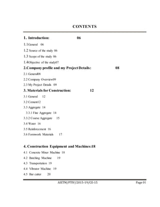
  • 1. AIETM/PTIV/2015-19/CE-15 Page 01 CONTENTS 1. Introduction: 06 1.1General 06 1.2 Source of the study 06 1.3 Scope of the study 06 1.4Objective of the study07 2.Company profile and my ProjectDetails: 08 2.1 General08 2.2 Company Overview09 2.3 My Project Details 09 3. Materials for Construction: 12 3.1 General 12 3.2 Cement12 3.3 Aggregate 14 3.3.1 Fine Aggregate 14 3.3.2 Coarse Aggregate 15 3.4 Water 16 3.5 Reinforcement 16 3.6 Formwork Materials 17 4. Construction Equipment and Machines:18 4.1 Concrete Mixer Machine 18 4.2 Batching Machine 19 4.3 Transportation 19 4.4 Vibrator Machine 19 4.5 Bar cutter 20
  • 2. AIETM/PTIV/2015-19/CE-15 Page 01 5. Construction of Building: 21 5.1 Sub-structure 21 5.1.1 Shallow foundation 22 5.1.1.1 Individual footings 22 5.1.1.2 Strip footing 23 5.1.1.3 Raft or Mat foundation 23 5.1.2 Deep foundation 24 5.1.2.1 Pile foundation 24 5.2 Super structure 25 6. Constructionof Beamand Slab: 28 6.1 Beam 28 6.2 Slab28 6.3 Framework28 6.4 Main component of shuttering 28 6.5 Shuttering Processes29 6.6 Centering of Beam and Slab 29 6.7 Reinforcement Placement of Slab and Beam 30 6.8 Casting of Beam and Slab 32 6.9 Curing of beam and Slab 32 7. Brick Masonry:33 7.1 Class of Brick 33 7.2 Size and Weight of Bricks 34 7.3 Structure of Brick 34 7.4 Types of Brick Masonry 35 7.5 Tools used in Brick Masonry 36 7.6 Bond in Brick Work36 7.8 Procedure of Brick Masonry 39
  • 3. AIETM/PTIV/2015-19/CE-15 Page 01 8. Plaster: 40 8.1 Mortar for Plastering 40 8.2 Tools for Plastering 41 8.3 Methods of Plastering 43 9. Building By-Laws: 45 9.1 Objectives of Building By-Laws 45 9.2 Plinth Area Regulations 45 9.3 Height and Size Regulation for Rooms 46 9.3.1Height Regulations 46 9.3.2Size Regulations 47 9.3 Lighting and Ventilation Regulations 47 9.5 Open Space Regulations 49 9.6 Fire Protection Regulations 50 Conclusion: 52 Reference:52
  • 4. AIETM/PTIV/2015-19/CE-15 Page 01 LIST OF FIGURES S no. Name Page no. 2.1 Unit Plan 10 2.2 Image ofbuilding 11 3.1 Cement 13 3.2 Fine aggregate 15 3.3 Coarse aggregate 15 3.4 Reinforcement 17 3.5 Formwork 17 4.1 Concrete mixer machine 18 4.2 Vibrator machine 20 4.3 Bar cutter machine 20 5.1 Individual Footing 23 5.2 Plinth Beam in Footing 23 5.3 Pile Foundation 25 5.4 Flooring 26 6.1 Props ofthe slab and beam 28 6.2 Steel sheet 30
  • 5. AIETM/PTIV/2015-19/CE-15 Page 01 6.3 Checking lapping distance ofbeam 30 6.4 Stirrup binding of beam 31 7.1 Bricks 33 7.2 Stretcher Bond 37 7.3 Header Bond 37 7.4 English Bond 38 7.5 Thickness ofWall 39 8.1 Plastering 41 LIST OF TABLES S.no Name Page no. 3.1 Composition ofPortland Cement 12 8.1 Different Coats ofPlaster 44 9.1 Maximum Permissible Covered Area 46
  • 6. AIETM/PTIV/2015-19/CE-15 Page 01 CHAPTER 1 INTRODUCTION 1.1General The internship is a bridge between the theoretical knowledge and the practical or the reality work at the field of civil engineering work. A practicum report is the storage of information which one did during of his training period at the selective project. In this report I tried to upload about my 2 month practicum period experience of the construction work of a G+4 storied high building. As a civil engineer theoretical knowledge is not enough for showing one skills in this competitive world. In my report here I tried to mention the information of a residential building construction project which situated at Sushant city karwar road Jaipur(RAJ.) 1.2Source of study The information provide in this report has been collected from the ongoing construction of “VASUNDHARA ANCHAL” a residential project of SHREE VINAYAK GROUP. Here I got an opportunity to observe and learn the day to day construction work and also learned many construction information from my project engineer that will help me for my professional life. I have learned many things which will be able to overcome the difficulties faced in theoretical part and also learned about material property, management system billing etc. 1.2 Scope ofthe study It is great opportunity for me to work in practical field as a trainee engineer in a leading developer company like SHREE VINAYAK GROUP . Here, I tried to apply my theoretical knowledge in practical field which I have acquired from my four years learning period. In my project here I worked with the engineer, contractor, labour and gathered much more basic knowledge on building construction which will be effective for my future career.
  • 7. AIETM/PTIV/2015-19/CE-15 Page 01 1.3Objective of the study Thepurpose of my internship to take the future leadership and also to take responsibilities in professional field of engineering technology. Mainly internship program is to meet the challenges of the future by enhancing the knowledge that is learnt during learning period and also for construction company. The main objective of my internship was to understand the construction work which was done in practical field. I observed the construction work and learned many more things about construction procedure and managements. S 2.1 General
  • 8. AIETM/PTIV/2015-19/CE-15 Page 01 With great gratitude we would like to inform you that we introducing ourselves as “SHREE VINAYAK GROUP” an experienced Architectural and Engineering consultancy firm since 1997. Here some information about SHRE VINAYAK GROUP. Company Name: SHREE VINAYAK GROUP Company Logo: Company Type: GROUP License Type: Consultancy (First class contractor) Experience: 1st phase starting1997 to 2018 onwards
  • 9. AIETM/PTIV/2015-19/CE-15 Page 01 Address: A-182, Kardhanishoping center, Hotel Royal In,kalwar road Jaipur (RAJ.) Phone No: 8426888111 Email: shreevinayakgroup44@gmail.com 2.2 Company Overview With gratitude we would like to inform you that we introducing ourselves as “SHREE VINAYAK GROUP” an experienced Architectural and Engineering consultancy firm since 1997. This firm has a diligent team of architects, engineers, planners, interior designers and management staff. All personnel are highly qualified, well trained, dynamic and sincere. We have architectural being trained especially to design moderate markets, factory building, clinics, modern residential apartment building and more. Hope this will suit your desire and will opportune us to serve your company. We strongly believe that we can add value to your organization by our services. 2.3 My ProjectDetail Type of Building: Residential building Location: SUSHANT CITY 1ST ,KALWAR ROAD, JAIPUR (RAJ.) No. of Floor: G+4(Ground floor+ 4 floor) Appartment Size: 1BHK=352.80sft and 2BHK=540.00sft
  • 10. AIETM/PTIV/2015-19/CE-15 Page 01 Unit Plan: Fig. 2.1 Unit Plan
  • 11. AIETM/PTIV/2015-19/CE-15 Page 01 Image of after complete construction: Fig 2.2Image of building
  • 12. AIETM/PTIV/2015-19/CE-15 Page 01 CHAPTER3 MATERIAL FOR CONSTRUCTION 3.1 General In construction of super structure, it is necessary to maintain good quality materials. I Observed different types of construction materials which were directly used for different construction work. The equipment and machineries that were used in this project are given below with basic information. 3.2 Cement A cement is a binder,a substance used for construction that sets, hardens, and adheres to other materials to bind them together. Cement is seldom used on its own, but rather to bind sand and gravel together. The approximate composition of Portland cement is given below Lime(Cao) 60-70% Silica(SiO2) 20-25% Alumina(Al2O3) 5-10% Ferric Oxide(Fe2O3) 2-3% Table 3.1 Composition of Portland cement
  • 13. AIETM/PTIV/2015-19/CE-15 Page 01 Fig. 3.1 Cement The function of cement is to combine with water and to form cement paste. This paste first sets i.e. it becomes firms and then hardens due to chemical reaction, called hydration, between the cement and water. On setting & hardening, the cement binds the aggregate together into a stone like hard mass & thus provides strength, durability & water-tighten to the concrete. Quality of cement is based on grade of cement. The grades of cement are as-  33 Grades  43 Grades  53 Grades  33 Grade OPC is used for general construction works like plastering and finishing works in normal environmental conditions. However, its use is virtually phased out today.  Coming to the 43 GradeOPC, it is the most commonly used grade for home construction. It has its applications in plastering, finishing works, precast items, foundations, brick work, and compound wall and so on. It has more strength development than the 33 grade cement.  53 Grade OPC develops strength very fast. High rise building constructions use 53 grade cement . This is applicable for use in structures where high grade concrete is required. At the site Portland cement of 53 grades (JK SUPER CEMENT) is used.
  • 14. AIETM/PTIV/2015-19/CE-15 Page 01 The cost per beg = 275 rupees The initial setting time of cement = 30 minutes (1/2 hour) The final setting time of cement = 10 hrs. 3.3 Aggregate Aggregates is a broad category of coarse to medium grained particulate material use in construction, include sand gravel, crushed stone slag, recycled concrete Geosyenthetic aggregates. Neat cement is very rarely used in construction works since it is liable to shrink too much and become cracks on setting. Moreover, it will be costly to use neat cement in construction work. Therefore cement is mixed with some inert strong & durable hard materials. They also reduce the cost of concrete because they are comparative much cheaper as cement. TYPES OF AGGREGATES:  Fine Aggregate  Coarse Aggregate 3.3.1 Fine Aggregate (sand): The aggregate, which pass through 4.75 mm, I.S. sieve and entirely retain on 75 micron (.075mm) I.S. sieve is known as fine aggregate. Fine aggregate generally consist of natural sand or crushed stone with most particles through a 3/8 inch sieve.
  • 15. AIETM/PTIV/2015-19/CE-15 Page 01 Fig. 3.2 Fine Aggregate The function of using fine aggregate in a concrete mix is to fill up the voids existing in the coarse aggregate and to obtain a dense and strong concrete with less quantity of cement and increase the workability of the concrete mix. 3.3.2 Coarse Aggregate: The aggregate, which pass through 75 mm I.S. sieve and entirely retain on 4.75 I.S. sieve is known as coarse aggregates. At the site the coarse aggregate was 10mm & 20mm (graded). Fig. 3.3 Coarse Aggregates
  • 16. AIETM/PTIV/2015-19/CE-15 Page 01 The coarse aggregates are used in mixing of concrete. It is mixed cement, sand with water. These aggregates increase the strength of bonding in aggregates. Coarse aggregates are used in construction of plan cement concrete (PCC), foundation, beams and columns etc. 3.4 WATER It is an important ingredient of concrete because it combines with cement and forms a binding paste. The paste thus formed fills up the voids of the sand and coarse aggregate bringing them into close adhesion. In this project source of water is a tube well which is closely spaced to the building. The quality of water is good and can be used for drinking purpose also. 3.5 REINFORCEMENT Reinforced concrete (R.C.) (Also called reinforced concrete cement or RCC) is a composite material in which concrete’s relatively low tensile strength and ductility are counteracted by the inclusion of reinforcement having higher tensile strength. Normally, the tensile strength of a concrete is about 10% to 15% of its compressive strength. Hence if a beam is made up of plain cement concrete, it has a very low load carrying capacity since its low tensile strength limits its overall strength. It is, there reinforced by placing steel bars in the tensile zone of the concrete beam so that the compressive bending stress is carried by concrete and tensile bending stress is carried by steel reinforcing bars. Generally in simply supported and Cantilever beams the tension zone occurs at bottom and top of beam respectively.
  • 17. AIETM/PTIV/2015-19/CE-15 Page 01 Fig 3.4 Reinforcement 3.6 FORMWORKMATERIALS Varieties of materials used for making concrete formwork depending on availability of materials economical consideration etc. Bamboo, steel sheet, wooden runner, planks etc. were used for formwork in my site. Fig 3.5 Formwork
  • 18. AIETM/PTIV/2015-19/CE-15 Page 01 CHAPTER4 CONSTRUCTION EQUIPMENTS AND MACHINES 3.7CONCRETE MIXER MACHINE Concrete mixer machine is used to combine the cement, water, fine aggregate (sand) and course aggregate to from concrete. This is a power mechanically operated machine which is used to mix the concrete. It consists a hollow cylindrical part with inner side wings. In which cement, sand, aggregates and water is mix properly. Fig 4.1 Concrete mixer machine
  • 19. AIETM/PTIV/2015-19/CE-15 Page 01 3.8 BATCHING MACHINE The measurement of materials for making concrete is known as batching. The machines which used for batching is known as batching machine. In this equipment that combine various ingredients to from concrete. Some of these input include water, air, admixtures, sand, aggregate (rock ,gravel etc.), fly ash, silica fume, slag and cement. 4.3TRANSPORTATION The process of carrying the concrete mix from the place of it’s mixing to final position of deposition is termed as transportation of concrete. There are many methods of transportation as mentioned below-  Transport of concrete by pans  Transport of concrete by wheel barrows  Transport of concrete by tipping Lorries  Transport of concrete by pumps  Transport of concrete by belt conveyors 4.4VIBRATOR MACHINE Vibrator machine provides a better material flow and remove air bubbles. But excessive vibration will be aggregate the concrete mixture. A vibrator is a mechanical device to generate vibrations. The vibration is often generated by an electric motor with an unbalanced mass on its driveshaft.
  • 20. AIETM/PTIV/2015-19/CE-15 Page 01 Fig 4.4 Vibrator Machine 4.5BAR CUTTER Bar cutter is also an electric machine from which steel bars can be cut efficiently.Bar cutter also known as REBAR CUTTER are the tool that are specifically designed to cut reinforcement steel bars. They allow builders to provide the correct structural integrity. Cutting through any steel can be challenging due to the material thickness. Fig 4.5Bar Cutter Machine
  • 21. AIETM/PTIV/2015-19/CE-15 Page 01 CHPTER5 CONSTRUCTION OF BUILDING Construction of the building is done in two steps. Which are following:  Sub Structure  Super Structure. 5.1 Sub-structure It is the structure which is below the ground level and consists of basement as well as the foundation. Foundation is part of substructure. Substructure is the lower portion of the building which transmits the dead load, live loads and other loads to the underneath sub soil. Sub structure is constructed according to soil quality at that site. If soil have good bearing capacity than we use shallow foundation in construction. And if the bearing capacity of the soil is not good or suitable than we use deep foundation at that site. FOUNDATION: A foundation is the element of any structure which connects it to the ground, and transfers loads from the structure to the ground. Foundations are generally considered either shallow or deep. The low artificially built part of a structure which transmits the load of the structure to the ground is called foundation. Foundation is a load bearing structure which bear all loads coming on the building or any structure. Foundation is generally of two types: 1) Shallow Foundation. 2) Deep Foundation.
  • 22. AIETM/PTIV/2015-19/CE-15 Page 01 5.1.1 SHALLOW FOUNDATION A shallow foundation is a type of building foundation that transfers building loads to the earth very near to the surface, rather than to a subsurface layer or a range of depths as does a foundation. The idea is that each footing takes the concentrated load of the column and spreads it out over a large area, so that the actual weight on the soil does not exceed the safe bearing capacity of the soil. It includes some types of shallow foundation such as: 5.1.1.1 INDIVIDUAL FOOTING Individual footings are one of the most simple and common types of foundations. These are used when the load of the building is carried by columns. Usually, each column will have its own footing. The footing is just a square or rectangular pad of concrete on which the column sits. To get a very rough idea of the size of the footing, the engineer will take the total load on the column and divide it by the safe bearing capacity (SBC) of the soil. For example, if a column has a vertical load of 10T, and the SBC of the soil is 10T/m2, then the area of the footing will be 1m2. In practice, the designer will look at many other factors before preparing a construction design for the footing and when the footing supports a separate column, it is referred as individual footing. It is sometimes denoted as spread footing or isolated footing. For the purpose of analysis, footing may be considered as a sample flat plate or slab. It can be square in plain acted upon by the load onto soil.Individual footings are usually connected by a plinth beam, a horizontal beam that is built at ground or below ground level.
  • 23. AIETM/PTIV/2015-19/CE-15 Page 01 Fig5.1 Individual Footing Fig5.2 Plinth beam in Footing 5.1.1.2 STRIP FOOTING Strip footings are commonly used as foundations of load bearing walls. The footing usually has twise in width as the load bearing wall sometimes it is even wider. The width as well as the type of reinforcement are depending on the bearing capacity of the foundation soil. 5.1.1.3 RAFT OR MAT FOUNDATION Both are same thing, when soil bearing capacity is low or when the columns are closely spaced in a 2D grid then we go for a mat/raft footing. It also helps when outer columns of the grid flish with property line. Raft Foundation is a thick concrete slab reinforced with steel which covers the entire contact area of the structure like a thick floor. Sometimes area covered by raft may be greater than the contect area depending on the bearing capacity of the soil underneath. The reinforcing bars runs normal to each other in both top and bottom layers of steel reinforcement.
  • 24. AIETM/PTIV/2015-19/CE-15 Page 01 Mat Foundations are used where the soil is week, and therefore building loads have to be spread over a large area, or where columns are closely spaced, which means that if individual footings were used, they would touch each other. 5.1.2 DEEP FOUNDATION A deep foundation is a type of foundation which transfers building loads to the earth farther down from the surface than a shallow foundation does, to a subsurface layer or a range of depths. 5.1.2.1 PILE FOUNDATION A pile is basically a long cylinder of a strong material such as concrete that is pushed into the ground so that structures can be supported on top of it. Pile foundations are used in the following situations: 1) When there is a layer of weak soil at the surface. This layer cannot support the weight of the building, so the loads of the building have to bypass this layer and be transferred to the layer of stronger soil or rock that is below the weak layer. 2) When a building has very heavy, concentrated loads, such as in a high rise structure. Pile foundations are capable of taking higher loads than spread footings. There are two types of pile foundations, each of which works in its own way. Fig 5.3 Pile foundation
  • 25. AIETM/PTIV/2015-19/CE-15 Page 01 End Bearing Piles In end bearing piles, the bottom end of the pile rests on a layer of especially strong soil or rock. The load of the building is transferred through the pile onto the strong layer. In a sense, this pile acts like a column. The key principle is that the bottom end rests on the surface which is the intersection of a weak and strong layer. The load therefore bypasses the weak layer and is safely transferred to the strong layer. Friction Piles Friction piles work on a different principle. The pile transfers the load of the building to the soil across the full height of the pile, by friction. In other words, the entire surface of the pile, which is cylindrical in shape, works to transfer the forces to the soil. To visualize how this works, imagine you are pushing a solid metal rod of say 4mm diameter into a tub of frozen ice cream. Once you have pushed it in, it is strong enough to support some load. The greater the embedment depth in the ice cream, the more load it can support. This is very similar to how a friction pile works. In a friction pile, the amount of load a pile can support is directly proportionate to its length. 5.2 SUPER STRUCTURE Super-structure is the structure which is above ground level and includes elements of a structure which rises or rests on it foundation. A superstructure is an upward extension of an existing structure above a base line of physical structure such a building. Following are the important parts of super-structure. 1) Floor 2) Roof 3) Lintel 4) Parapet 5) Sun Shade 6) Doors & Windows
  • 26. AIETM/PTIV/2015-19/CE-15 Page 01 FLOOR Fig.5.4 Flooring Floor is that part of a building on which furniture, household, commercial, industrial or any other type of items is stored. Floor is used for walking around.Floor separates the different levels of a building. Building is also named with reference to floor. Like Ground floor, first floor, or a floor that is below ground level like basement floor. ROOF Roof is the covering on the uppermost part of a building or shelter which provides protection from animal and weather, notably rain or snow, but also heat, wind and sunlight.. Different types of roofs are used in building depending on the location and weather. Sloping roofs are generally considered better in mountain areas. While, in plan areas flat roofs are preferred.
  • 27. AIETM/PTIV/2015-19/CE-15 Page 01 LINTEL Lintel is a structural horizontal block that spans the space or opening between two vertical support. It can be a decorative architectural element, or a combined ornamented structural item . Lintel beam is generally made as reinforced cement concrete member. While, in residential houses sometime lintel is made by using concrete and bricks. Breadth of lintel is generally equals to the breadth of wall. In case of metric unit, it is normally equals to 10cm, 15cm, 20cm etc. While, in case of FPS system it is consider as 6”, 9”, 12” etc. Thickness of lintel should not be less than 10cm (4.5”) and maximum thickness of lintel should not be more than its breadth. SUN SHADE Sunshade is a metal louver installed horizontally over a window and/or vertically in fornt of a window to prevent the infiltration of solar heat or glare while allowing daylight views. Initially metal sunshade were called eyebrows and simply added an additional dimension to a relatively flat surface. They were seen as more of building aesthetic feature than a functional feauture. DOORS AND WINDOWS A door is a moving structure used to block off, and allow access to, an entrance to or within an enclosed space, such as a building or vehicle. Doors normally consist of a panel that swings on hinges on the edge, but there are also doors that slide or spin inside of a space. CHAPTER6
  • 28. AIETM/PTIV/2015-19/CE-15 Page 01 CONSTRUCTION OF BEAM AND SLAB 6.1 BEAM Beam is the horizontal member of a structure carrying transvers loads. Beam carries load from the floor slab or the roof slab and transvers all the loads including its self -weight to the columns or wall. 6.2 SLAB The slab provides surface and is usually supported by columns, beams or walls. Slabs may be define as those structural elements that are subjected to distribute loads primarily in a plane transverse to the plane of slab. It is supported by reinforced concrete beams. 6.3 FORMWORK Mainly two type of formwork use in construction site, one is timber formwork and other is steel formwork. Timber is the most common material used for formwork. In my site has been used timber formwork. Timber for formwork should satisfy the following requirement, well-seasoned, light in weight, easily workable with nails without splitting, free from loose knots. Timber used for shuttering for exposed concrete work should have smooth and even surface on all faces which come in contact with concrete for timber formwork. 6.4 MAIN COMPONENTSOF SHUTTERING Bamboo has been used as props in my project. The diameter of bamboo was not less than 3-4 cm in. Wooden runner is used in my project and its size is 3`*2`. Also wooden planks are used in my project and its size was size 5`*1.5`. Steel sheet has been used for shuttering.
  • 29. AIETM/PTIV/2015-19/CE-15 Page 01 Fig.6.1 Props of the slab and beam Fig.6.2 Steel sheet 6.5 SHUTTERING PROCESSES At first bottom shutter was placed top of column. Then the workers used bamboo props for support. Horizontal distances between were 2-2.5feet. After finishing bottom was 2feet to 2.5feet. After placing runner, horizontally they placed planks and planks spacing was 5inch to 6inch. At last they placed steel sheet. 6.6 CENTERINGOF BEAM AND SLAB Before casting, we should complete centering. The following terms were considered during centering of slab. Checking vertical props, checking runner spacing, checking planks spacing, laying of the steel sheet. Water leveling has been used for centering in my site. By using water level and they tried a rope above from shutter and marked it using red color tapes with steel bar. Then moved this bar place to place and checked where did not match rope and red marking.
  • 30. AIETM/PTIV/2015-19/CE-15 Page 01 6.7 REINFORCEMENTPLACEMENTOF BEAM In my site, 16mm diameter and 20mm diameter bar was used as main bar and 10mm diameter bar was used for beam stirrups. Mainly five types of bar were used for beam. They are: top bar, bottom bar, extra top bar, extra bottom bar and stirrup. Top bar is placed in the compression zone of beam, bottom bar is placed in the tension zone of beam, extra top is provided on the beam support at top of beam and extended up to L/4 distance of beam clear span both side of support. Extra bottom bar is provided in the middle of beam bottom portion. Stirrup is often called ring in the construction sector. It is the shear reinforcement. At first, bar were cut according to the required length given in the drawings. Reinforcement of beam are arranged above the beam formwork. Whole frame was made outside the shutter. Longitudinal bars were placed first, and then extra bars were placed. After that I observed the arrangement of stirrup between two layers of bar. Reinforced bar for beam were bent at the both end to L shape according to the design. This work was done only for the top bar and bottom bar of the beam. After binding of all reinforcement the whole structure was placed into the shutter. Concrete blocks were used to maintain the clear cover of the beam.
  • 31. AIETM/PTIV/2015-19/CE-15 Page 01 Fig.6.3 Checking lapping distance of beam Fig.6.4 Stirrup binding of beam
  • 32. AIETM/PTIV/2015-19/CE-15 Page 01 6.8 CASTING OF BEAM AND SLAB After finishing binding all reinforcement, it was time for casting slab, beam and stair were being casted at a time. Before casting final checking proceeds mainly on rebar lapping, stirrup arrangement, stirrup spacing ext. top length, beam depth, clear cover and main bar counting and bar arrangement according to design requirement. In my site, the worker used cement, sand, brick chips and the ratio was M25. Cylinder test was taken to check the strength and get strength 3500 psi. Only column and beam crossing zone casting was done with stone chips. Used a mixer machine for mixing cement, sand, bricks chips and water together. After that mixed materials were put into a crane which is used for pulling up the concrete to the top of the building for casting. At first they casted and beam crossing zone. After finishing column and beam crossing zone casting cast beam strip then slab portion. At the time of casting, they used vibrator machine which is most important equipment for casting. Vibration provides a good material flow and removes air bubbles. But excessive vibration will be segregated the concrete mixture. Steel runner was used for surface was used for surface leveling. U shape ring was placed on casted slab for further column shuttering. 6.9 CURING OF BEAM AND SLAB Concrete hardens as a result of the chemical reaction between cement and water. Chemical reaction occurs only if water is available and if the concrete temperature stays within a suitable range. Concrete get water by the process of curing. So, curing is one of the most important steps in concrete construction. Proper curing greatly increases concrete strength and durability and also reduces cracks. Curing time minimum 21-28 days. Usually in the beam without slab section is done by wrapping of most jute fabric and by sprinkling water by hose pipe frequec.
  • 33. AIETM/PTIV/2015-19/CE-15 Page 01 CHAPTER7 BRICK MASONARY The bricks are obtained by molding clay in rectangular block of uniform size and then drying and burning these blocks. Brick masonry easy to construct compare stone masonry. It is less time consuming and there is no need of skilled labour to construct it. The bricks do not require dressing and the arty of laying bricks is so simple. 7.1 CLASS OF BRICKS: On the basis of quality and performance of brick is classified in three parts- CLASS A CLASS B CLASS C At this site A class brick is used. Fig. 7.1 Bricks
  • 34. AIETM/PTIV/2015-19/CE-15 Page 01 7.2 SIZE AND WEIGHT OF BRICKS: The bricks are prepared in various sizes. On the basis of size , BIS bricks are categories in two parts- MODULAR BRICKS: BIS recommends a standard size of brick which is 190mm*90mm*90mm. With mortar thickness, size of such a brick become 200mm*100mm*100mm. TRADITIONAL BRICKS: The brick of which size varies and not standardized known as traditional brick. WEIGHT OF BRICK: It is found that the weight of 1 cubic meter brick earth is about 1800 kg. Hence the average weight of a brick will be about 3 to 3.5 kg. 7.3 STRUCTURE OF BRICK: STRETCHER: If brick laid along its length then front view of brick is known as stretcher. HEADER: If brick laid along it’s width , then front view of brick is known as header. FROG: It is top of brick. It provides strong bonding between two courses of masonry by filling the mortar. It also consists the name of company. QUEEN CLOSER: This is obtained by cutting the bricks longitudinally in two equal parts. BAT: This is piece of brick , considered in relation to the length of brick as half bat, three quarter bat, etc. 7.4 TYPES OF BRICK MASONARY: Brick work is classified according to quality of mortar, quality of brick and thickness of joints. They types of brick work as follows-
  • 35. AIETM/PTIV/2015-19/CE-15 Page 01 BRICK WORK IN MUD MORTAR: IN this type of brick work mud is used to fill up the joints. Mud is mixer of sand and clay. The thickness of mortar joint is 12mm. BRICK WORK IN LIME MORTAR: In this type of brick work, lime mortar is used to fill up the joints. Lime mortar is mixer of lime and sand the thickness of joints does not exceeds 10mm. BRICK WORK IN CEMENT MORTAR: In this type of brick work ,cement mortar is used to fill up the joints. Cement mortar is mixer of cement and sand in ceftain ratio. The ratio Of cement and sand varies according to construction as in brick masonary it generally kept 1:6.The thickness of joint does not exceeds 10mm. The brick work with cement mortar provide high adopted in building construction. At this site cement mortar is used in brick work. The ratio of Cement to sand is 1:6. 7.5 TOOLS USED IN BRICK MASONRY: The tools used in brick masonry are trowel, spirit level, plumb bob, square, hammer, straight edge. 7.6 BONDS IN BRICK WORK: There various bonds which provided in brick work to increase the stability of walls. Various types of bonds are as follows- Stretcher Bond Header Bond English Bond Flemish Bond STRETCHER BOND : The bricks are laid along its length in all courses. A half and three quarter bat is used in alternative courses to break the verticality of joints.
  • 36. AIETM/PTIV/2015-19/CE-15 Page 01 Fig. 7.2 Stretcher Bond HEADER BOND: The bricks are laid along its width in all courses. A half and three quarter bat is also used in alternative courses to break the verticality of joints. Fig:7.3 Header Bond of Brick
  • 37. AIETM/PTIV/2015-19/CE-15 Page 01 ENGLISH BOND: This bond is widely used in practice. It is consider the strongest bond. Alternate courses consist of stretcher and header. A queen closer is put next to quoin header to break the verticality of joints. Generally such types of bond is provided in walls width is 9 inches. At this site ENGLISH BOND is prefer in main wall and STRETCHER BOND in partition walls. Fig. 7.4 English Bond FLEMISH BOND: This is also widely used because it gives better appearance to English bond. It also provides good strength. Stretcher and header is provided in each course alternatively. A queen closer is put next to quoin header in each alternate course to break the verticality of joints. 7.7 THICKNESS OF WALLS: Thickness of wall depend on load, strength of material, length of wallet. In this project the thickness of main wall is 9 inches and partition wall is 4.5 inches.
  • 38. AIETM/PTIV/2015-19/CE-15 Page 01 Fig. 7.5 Thickness of Wall 7.8 PROCEDUREOF BRICKMASONRY: In frame structure brick work starts after construction of foundation, column, beam, and slabs. Following procedure is adopt to construct the brick masonry- 1. Initially clean and wet the surface on which brick wall is be constructed. 2. Set a straight alignment by using threads in both side of a wall . 3. Prepare the cement mortar. 4. At this site cement sand ratio is 1:6 for all walls. 5. Mortar is laid on surface base and then bricks are laid over it . 6. Prepare a course and then again laid the mortar on existing course and provides bricks in such a way that the vertical joint should not stand in a line. 7. To break the verticality of joints generally English or Flemish bond is adopted. 8. Use the plumb bob to check the verticality at regular interval. 9. Also use square to check the wall is constructing straight or not. 10. After each 1meter height of wall provide a layer of reinforced cement concrete of 1.5 to 2 inches.
  • 39. AIETM/PTIV/2015-19/CE-15 Page 01 CHAPTER 8 PLASTER The term plastering is used to describe thin cover that is applied on the surface of walls. It removes unevenness of surface of walls. Sometimes it is use for decorative purpose also. 8.1MORTAR FOR PLASTERING: Selection of type of mortar depends on various factors such as suitability of building material, atmospheric conditions, durability etc. there are mainly three type of mortar which can be used for the purpose of mortar Lime mortar Cement mortar Water proof mortar LIME MORTAR: The main content of lime mortar is lime that is mixed with correct proportion of sand. Generally fat lime is recommended for plaster work because the fat lime contains 75% of CaO and it combines with CO2 of atmosphere and gives CaCO3 quickly. Thus, the lime sets quickly, but it imparts low strength. So it can be use only for plaster work. The sand to be used for preparing lime mortar for plastering work should be clean, coarse and free from any organic impurities. CEMENT MORTAR: The cement mortar consists of one part of cement to four part of clean and coarse sand by volume. The materials are thoroughly mix in dry condition before water is added to them. The
  • 40. AIETM/PTIV/2015-19/CE-15 Page 01 mixing of material is done on a watertight platform. It is better than lime mortar. It is widely used in construction work. Fig. 8.1 Plastering WATER PROOF MORTAR: Water proof mortar is prepared by mixing one part of cement, two part of sand and pulverized alum at the rate of 120Nperm3 of sand. In the water to be used, 0.75 of soft soap is dissolve per one liter of water and this soap water is added to the dry mix. 8.2 TOOLS FOR PLASTERING: Gauging Trowel Metal Float
  • 41. AIETM/PTIV/2015-19/CE-15 Page 01 Brushes 8.3 METHOD OF PLASTERING: According to the thickness of wall there are three method of plastering. One coat method Two coat method Three coat method ONE COAT METHOD: It is in the cheapest form of construction that plaster is applied in one coat. This method is quietly used in rural areas for the construction of low category and cheap house. TWO COAT METHOD: Following procedure is carried out for two coating plaster work Clean the surface and keep it well watered on which plaster work to be done. If it is found that the surface to be plastered is very rough and uneven, a preliminary coat is applied to fill up the hollows before the first coat of plaster is put up on the surface. Now the first coat is applied on the surface. The usual thickness of first coat for brick masonry is 9mm to10mm. Second coat of plaster is applied after about 6 hours and the thickness of second coat is usually about 2mm to 3mm.It is finished as per requirement. THREE COAT METHOD: The procedure for plaster in three coats is the same as above except that the no. of coats of plaster is three.
  • 42. AIETM/PTIV/2015-19/CE-15 Page 01 Table: Name ofcoat Thickness First coat Rendering coat 9 to 10 mm Second coat Floating coat 6 to 9 mm Third coat Finishing coat 3 mm Table 8.1 Different Coats of Plaster
  • 43. AIETM/PTIV/2015-19/CE-15 Page 01 CHAPTER 9 BUILDING BYLAWS For the construction of any building, certain restrictions are laid down by Municipal bodies, urban development authorities, and other government departments as town planning trusts to clear open spaces to be left around the buildings. 9.1 OBJECTIVE OF BUILDING BYLAWS:  Allows disciplined and systematic growth of buildings and towns and prevent haphazard development.  Protect safety of public against fire, noise , health hazards and structural failures.  Provides proper utilization of space. Hence maximum efficiency in planning can be derived from these bylaws.  They give guidelines to the architect or an engineer in effective planning and useful in preplanning the building activates.  They provide health, safety and comfort to the peoples living in the building.  Due to these bylaws, each building will have proper approaches, light air, ventilation which is essential for health, safety and comfort. 9.2 PLINTH AREA REGULATIONS: The minimum area of buildings of different classes shall be governed by the following: 1. In an industrial plot, the plinth area should not exceed 60% of the site area. 2. In a market area, the plinth area should not exceed 75% of the area of site, provided sufficient off-street parking facilities for loading and unloading of vehicles are provided on the same plot as the building. 3. In residential plots, the covered areas should be as given in the table 1.
  • 44. AIETM/PTIV/2015-19/CE-15 Page 01 S.no Area of plot Maximum permissible covered area 1 Less than 200 sq. m 66.66 % ofthe plot area on the ground. 2 201 to 500 sq.m 50% of the plot area or 133 sq.m whichever is more. 3 501 to 1000 sq.m 40% of the plot area or 250 sq.m whichever is more. 4 More than 1000 sq.m 33.33 % of the plot area or 400 sq.m whichever is more. Table 9.1 Maximum permissible covered area 9.3HEIGHT AND SIZE REGULATIONS FOR ROOMS: 9.3.1 HEIGHT REGULATIONS:  Habitable rooms: The minimum height from the surface of the floor to the ceiling or bottom of slab should be not less than 2.75m. For air-conditioned rooms, a height of not less than 2.4 m measured from the top of the floor to the lowest point of the air- conditioning duct or the false ceiling should be provided.  Bathrooms, water closets and stores: The height of all such rooms measured from the floor in the ceiling should not be less than 2.4m. In the case of a passage under the landing, the minimum headway may be kept as 2.2m.  Kitchen: The height of the kitchen measured from the floor to the lowest point in the ceiling should not be less than 2.75m except for the portion to accommodate floor trap of the floor.
  • 45. AIETM/PTIV/2015-19/CE-15 Page 01 9.3.2 SIZE REGULATIONS:  Habitable rooms: The area of habitable rooms should not be less than 9.5sq.m where there is only one room. Where there are two rooms, one of these should not be less than 9.5sq.m and other be not less than 7.5sq.m with a minimum width of 2.4m.  Kitchen: Minimum floor area required is not less than 5.5sq.m. It should not be less than 1.8min width at any part. With a separate storeroom, the area may be reduced to 4.5sq.m. A kitchen cum dining room should have a floor area not less than 9.5sq.m with a minimum width of 2.4m. Each kitchen should be provided with a flue.  Bathrooms and water closets: The size of bathroom should not be less than 1.5m x 1.2m or 1.8sq.m. If it is combined with water closet, its floor area should not be less than 2.8sq.m the minimum floor area of a water closet should be 1.1 sq. m. 9.4 LIGHTING AND VENTILATION REGULATIONS: a) Rooms: Every habitable room which should have for the admission of air and light, one or more apertures such as windows and fanlights, opening directly to the external air or into an open verandah and of an aggregate area, inclusive of frames, of not les than i. One-tenth of the floor area excluding doors for dry hot climate. ii. One-sixth of the floor area excluding doors for wet/hot climate. No portion of a room should be assumed as lighted if is more than 7.5m away from the door or window which is taken for calculation as ventilating that portion. Cross-ventilation by means of windows and ventilators or both shall be affected in at least living room of tenement either by means of windows in opposite walls or if this is not possible or advisable, then atleast in the adjoining walls. b) Bathrooms and water closets: The rooms should be provided with natural light and permanent ventilation by one of the following means:
  • 46. AIETM/PTIV/2015-19/CE-15 Page 01 i. Windows having an area of not less than 10% of the floor area and located in an exterior wall facing a street alley, yard or an air shaft whose dimensions in the direction perpendicular to the window is not less than one-third the height of the building on which the window is located, subject to a minimum limit of 1m and maximum 6m. ii. Skylights, the construction of which shall provide light and ventilation required in (i) above. iii. Ventilation ducts: Provided such ducts have 130 square cm of area for each square meter of area with a minimum total area of 300 square cm and least dimension of 9cm. c) Stores, backrooms: These will have at least half the ventilation required for living room. d) Basement and floors: Basements and rooms located therein except room shall be lighten and ventilated by windows in exterior walls having a ventilating area of not less than 2.5% of the floor area. e) Kitchen shall be ventilated according to standards prescribed for habitable rooms near the ceiling as far as possible. f) Stairways: every staircase should be lighted and ventilated from an open air space of not less than 3m depth measured horizontally in case of ground and one upper floor structure, 4.5 m in case of ground and two upper and in higher structure than this, the open air space shall not be less than 6m, provided that the lighting area shall not be less than 1 sq.m per floor height. Every staircase shall be ventilated properly. 9.5 OPEN SPACE REGULATIONS: OPEN SPACE AROUND RESIDENTIALBUILDINGS Front open space: every building should have a front yard of minimum width of 3m and in case of two or more sides a width of an average of 3 m but in no case it shall be less than 1.8 m. Such a yard shall form an inseparable part of the site. Rear open space: Every residential building shall have a yard of an average width of 4.5 m and at no place the yard measuring less than 3 m as an inseparable part of the building, except in the case of back to back sites where the width of the yard could be reduced to 3m provided no erection, re-erection or material alteration of the building shall be undertaken, if at common plot
  • 47. AIETM/PTIV/2015-19/CE-15 Page 01 line straight lines drawn downwards and outwards from the line of intersection of the outer surface of any rear wall of the building with the roof perpendicular to that line form an angle of more than 63.5 degree to the horizontal. Side open space: every residential building may have a permanently open air space not less than 1m in width on one of its sides other than its front and rear and such side open space shall form an inseparable part of the site. In case, side open air space is to be used for ventilation, it shall be in accordance with the requirements mentioned in the previous paragraph. In case, the side open space abuts a road, the width shall not be less than 3m. 9.6 FIRE PROTECTION REGULATIONS: High-rise buildings have unique challenges related to fire protection such as longer egress times and distance, evacuation strategies, fire department accessibility, smoke movement and fire control. The numbers of persons living on high-rise buildings are high compared to low-rise buildings, and only evacuation method in case of fire is the staircase. So, the fire protections of high rise buildings have gained significant attention worldwide. Thus, in case of high rise buildings, the following provision should be made for safety of buildings from fire: 1. National building code should be followed for fire-safety requirement of high rise structures and at least one lift should be designed as fire-lift as defined in the Code and be installed. 2. At least one stair-case shall be provided as a fire staircase as defined in the National Building Code. Provided that this shall not be applicable if any two sides of a staircase are kept totally open to external open air space. 3. Water Supply: Underground tank of the capacity of one lakh liters and two lakh liters for the buildings situated within the municipal limit and outside of the municipal limit respectively be invariably provided in all the high rise buildings. Water in the normal use tank should come only through the overflow of fire tank so provided. 4. In high rise buildings, the internal fire hydrants shall be installed as provided in the National Building Code or as prescribed in the Indian Standard Code of practice for installation of
  • 48. AIETM/PTIV/2015-19/CE-15 Page 01 internal fire hydrants in high rise buildings. The detailed plan showing the arrangement of pipe lines, booster pumps and water-tanks at various levels shall be submitted for approval of the concerned authority along with the plans and sections of the buildings. 5. In case of high rise buildings, an external fire hydrant shall be provided within the confines of the site of the building and shall be connected with Municipal Water mains not less than 4″ in diameter. In addition, fire hydrant shall be connected with Booster Pump from the static supply maintained on site. 6. In case of high rise buildings separate electric circuits for lift installation, lighting of passages, corridors and stairs and for internal fire hydrant system shall be provided. 7. All the requirements under the above regulations shall be clearly indicated on plans duly signed by the owner and the person who has prepared the plans. The Competent Authority may direct the owner to submit such further drawings as may be necessary to clarify the implementation of the provisions of the above regulations. 8. Every building having a height of more than 25 Mts. shall be provided with diesel generators which can be utilized in case of failure of the electricity. 9. The standard of National Building Code must be adopted fully in providing stair-case and alarm system. 10. There should be Provision of dry-powder fire extinguisher to the extent of two on each floor with a capacity of 5 kgs, in all the high rise buildings.
  • 49. AIETM/PTIV/2015-19/CE-15 Page 01 CONCLUSION The general terms of construction are included in this study. Different types of Bonds in brick masonary are also studied in this report. Study about different types of foundation is also studied in this report. Study about the different Building By-laws is also done in this report. As per my training report I have conclude that , during last 60 days I am familiar with the construction of brick masonry & plastering and other works under a Rajasthan Housing Board project. Brick masonry is provided to transfer the load of structure to foundation. All though maximum load of building comes on columns and beams. Plaster is necessary to cover and protect the masonry from weathering factor. It is a layer of cement mortar of thickness is 1 to 1.5 inches. The basic knowledge of field is also important for my future. I am very thankful to all those people who help me to get knowledge of brick masonry and plastering.
  • 50. AIETM/PTIV/2015-19/CE-15 Page 01 REFERENCES  Ashok Dhaka (Project Manager at site)  Google.com  Wikipedia  I.S Codes for building construction  Building By-laws  Books on Building Construction