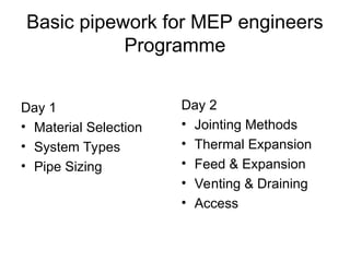
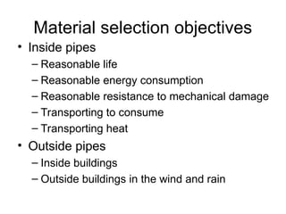
Material selection objectives
•Inside pipes
– Reasonable life
– Reasonable energy consumption
– Reasonable resistance to mechanical damage
– Transporting to consume
– Transporting heat
• Outside pipes
– Inside buildings
– Outside buildings in the wind and rain
Watch it
• Whydo contractors offer alternative
materials?
• Joint failures in plastics
– Special tools / joint preparation
– Material losses / shortages
23.
References
• “How greenare my pipe sizes” Arup
feedback note 1991NS_2
• Arup application guide – Water treatment
for HVAC systems
• Arup water treatment course for MEP
engineers.
• CIBSE 1986 Guide B10
• www.durapipe.com for plastics
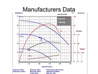
Manufacturers Data
Project TitleGlobal Switch Carrier Hotel
Pump Name Condenser Water Pumps DATE REV. PAGE
Tag No. RP - 1 TO 8 29-Aug-02
Doc. Title PUMP PERFORMANCE CURVES
Watch it
• Pumpvibration and inertia bases
• Net Positive Suction Head (NPSH)
• Water hammer
• Water quality
• Gravity circulation
• Control valve shut off
Compressed Air
• GalvanisedSteel, Stainless Steel, ABS,
Powder coated Aluminium or Copper
normally used
• Ring Main or Single Line Distribution
• Minimise Leaks
• Condensation trapping normally required
• Pipes sloped (1:100) to help with drain down
• All take-offs off the top of the pipe
• Final filtration at point of use to protect
machinery
Ring Main
Single Line
Sizing
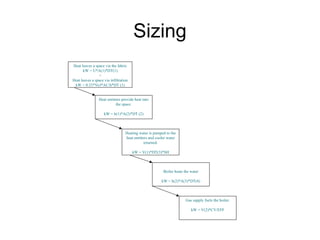
Heat leaves aspace via the fabric
kW = U*A(1)*DT(1)
+
Heat leaves a space via infiltration
kW = 0.33*Vol*AC/h*DT (1)
Heat emitters provide heat into
the space.
kW = h(1)*A(2)*DT (2)
Heating water is pumped to the
heat emitters and cooler water
returned.
kW = V(1)*DT(3)*SH
Boiler heats the water
kW = h(2)*A(3)*DT(4)
Gas supply fuels the boiler.
kW = V(2)*CV/EFF
69.
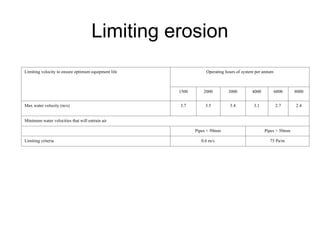
Limiting erosion
Limiting velocityto ensure optimum equipment life Operating hours of system per annum
1500 2000 3000 4000 6000 8000
Max water velocity (m/s) 3.7 3.5 3.4 3.1 2.7 2.4
Minimum water velocities that will entrain air
Pipes < 50mm Pipes > 50mm
Limiting criteria 0.6 m/s 75 Pa/m
70.
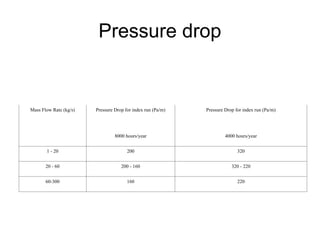
Pressure drop
Mass FlowRate (kg/s) Pressure Drop for index run (Pa/m) Pressure Drop for index run (Pa/m)
8000 hours/year 4000 hours/year
1 - 20 200 320
20 - 60 200 - 160 320 - 220
60-300 160 220
Sizing
a b cd e f g (f*g)+ c =h (h*e) = i j
Section
Thermal
Load
(kW)
Mass
flow rate.
(kg/s)
Pipe
length
F&R.
(m)
Pipe
diam.
(mm)
Pres.
Drop.
(Pa/m)
Equiv.
length
(m)
Sigma
Gamma
Fitting
factor
Total
length
(m)
Total
Pressure
Drop.
(KPa)
Velocity
(m/s)
A 60 2
B 40 3
C 40 2
D 20 4
E 60 5
F 40 6
G 80 8
H 110 6
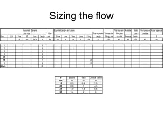
Sizing the flow
ØElbow Tee Check valve
mm m m m
15 0.5 0.6 2.5
22 0.8 1 4.3
28 1.0 1.5 5.6
32 1.4 2 6
Assumed Dynamic Equivilant Lengths and Losses Total pipe and Available Static Final pressure Actual pipe size
pipe size Pipe Total equivalent Total section fitting loss Loss - available
Pipe LU's Flow Ø Loss Length Loss Elbow Loss Tees Loss Fitting Length Fitting Loss to outlet Pressure Gain + Ø
l/s mm kPa / m m kPa no m no m kPa m kPa kPa kPa kPa kPa mm
1 5
2 6 2 1
3 3
4 6
4A 3
4B 1 20
5 9 1 20
Return 26
85.
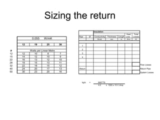
Sizing the return
Insulation
HeatTotal
Pipe Ø Conductivity Thichness Length Loss Losses
W/mK mm m W/m W
1
2
3
4
Flow Losses
Return Return Pipe
System Losses
kg/s = WATTS
4.2 x 1000 x 10 C drop
0.055 W/mK
12 19 25 38
Ø Watts per Linear Metre
12 12 10 8 7
15 14 12 10 9
22 16 13 12 10
28 19 15 13 11
32 22 18 15 12
40 24 20 17 13
50 30 23 20 16
Installers preference forplastics
• Light Weight = Easy to handle / distribute
• Can be installed by a semi skilled labour
force
• Reduced installation time
• May cost less?
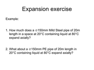
Expansion exercise
Example:
1. Howmuch does a 150mm Mild Steel pipe of 20m
length in a space at 20°C containing liquid at 80°C
expand axially?
2. What about a 150mm PE pipe of 20m length in
20°C containing liquid at 80°C expand axially?
125.
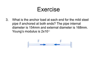
Exercise
3. What isthe anchor load at each end for the mild steel
pipe if anchored at both ends? The pipe internal
diameter is 154mm and external diameter is 168mm.
Young’s modulus is 2x10¹¹
126.
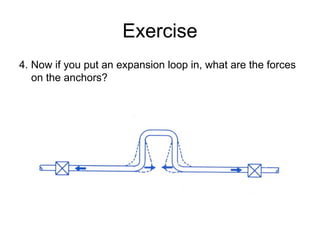
Exercise
4. Now ifyou put an expansion loop in, what are the forces
on the anchors?
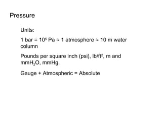
Pressure
Units:
1 bar =105
Pa ≈ 1 atmosphere ≈ 10 m water
column
Pounds per square inch (psi), lb/ft2
, m and
mmH2O, mmHg.
Gauge + Atmospheric = Absolute
130.
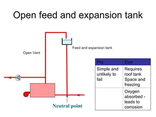
Open feed andexpansion tank
Pro Con
Simple and
unlikely to
fail
Requires
roof tank
Space and
freezing
Oxygen
absorbed -
leads to
corrosion
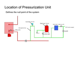
Neutral point
Watch it
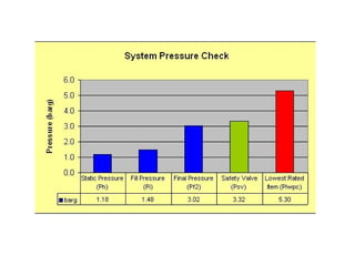
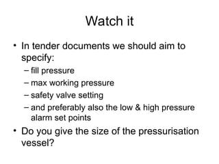
• Intender documents we should aim to
specify:
– fill pressure
– max working pressure
– safety valve setting
– and preferably also the low & high pressure
alarm set points
• Do you give the size of the pressurisation
vessel?
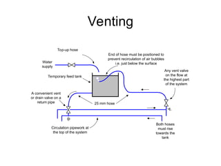
Venting
B
A
Circulation pipework at
thetop of the system
Both hoses
must rise
towards the
tank
Any vent valve
on the flow at
the highest part
of the system
End of hose must be positioned to
prevent recirculation of air bubbles
i.e. just below the surface
Top-up hose
Temporary feed tank
A convenient vent
or drain valve on a
return pipe
Water
supply
25 mm hose
149.
Watch it notes
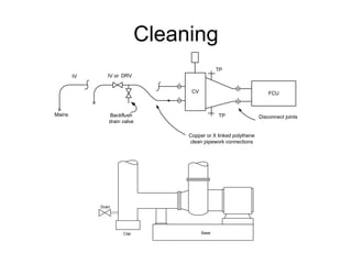
•Getting systems clean is important as
commissioning dirty systems will be
abortive.
• Use a water treatment specialist to provide
a flushing, cleaning and corrosion
inhibiting service.
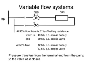
Variable flow systems
50%50%
p
At 90% flow there is 81% of battery resistance
which is 40.5% p.d. across battery
and 59.5% p.d. across valve
At 50% flow 12.5% p.d. across battery
87.5% p.d. across valve
Pressure transfers from the terminal and from the pump
to the valve as it closes.
155.
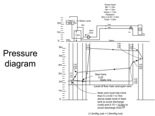
Pressure
diagram
Pump head
Blr =1.0m
Htr = 1.0m
Valve = 1.0m
Pipework
30m x 0.03 = 0.9m
Total = 3.9m
Level of flow main and open vent
2m
1m
0 FFL
tank
Feed
WL
Water Level
5m
1.5m
Start
here
10m
14m
1m
+
Datum
2m
1m
0
5m
4m
3m
6m
(1.0mWg cold =1.04mWg hot)
Start here
2.25
3.4
1.0
2.4
3.82
0.42
3.40
Static line
2.25
+3.90
6.15
5.85
1.00
4.85
6.15
0.30
5.85
4.85
0.03
4.82
4.82
1.00
3.82
Note vent must rise more
than 5 x 0.03 = 0.15m
above water level in feed
tank to avoid discharge
(cold) and 0.15 + (2.0m) to
avoid discharge (hot) 20
Watch it notes
•Commissioning is far to important to be left
to the contractor
• Don’t lose the commissioning time due to
delays in construction and client
completion dead lines.
• Rushing commissioning will not be in the
clients interest and makes design effort
valueless.
159.
References
• CIBSE WaterDistribution Systems -
Code W : 2003
• BSRIA Commissioning of Water Systems
in Buildings : AG 2/89
• Commissioning Specialists Association:
a. White Water Balancing : GN/1
b. Automatic Balancing Devices : GN/2
c. Variable Volume Water Systems : GN/3
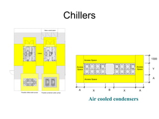
Chillers
Possible condenser waterpumps
Motor control panel
Chillers
Possible chilled water pumps
Chillers
X X
Y
A A
A
1300
B
Access Space
Access Space
Access
Space
Access
Space
Air cooled condensers
166.
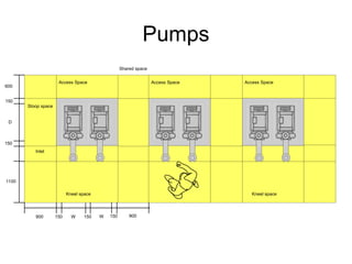
Pumps
Access Space
Kneel space
AccessSpace
150 150
150
W W
Shared space
900 900
Inlet space
Stoop space
Kneel space
Access Space
150
150
D
Stoop space
Inlet
600
1100
167.
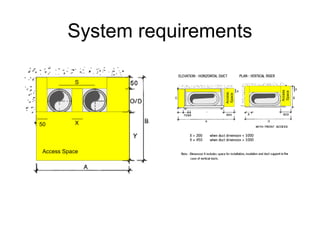
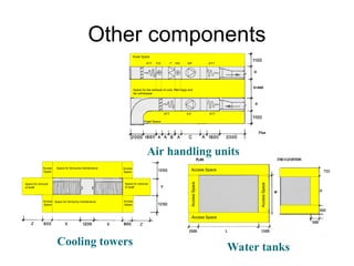
Other components
ATT F/CF H/C S/F ATT
ATT E/F ATT
Kneel Space
Kneel Space
Space for the removal of coils, filter bags and
fan withdrawal
D
D+600
D
Access
Space
Access
Space
Access
Space
Access
Space
Space for fan/sump maintenance
Space for fan/sump maintenance
Space for removal
of shaft
Space for removal
of shaft
750
Access Space
Access Space
Access
Space
Access
Space
Air handling units
Cooling towers Water tanks
168.
Watch it notes
•Do not let the architect or client push you
into agreeing to plant installation and
access space that is so constrained that it
is unhealthy or unsafe.
• Although this issue can be passed onto
the contractor, the plantrooms have to be
big enough for the contractor to comply
with the law.
169.
References
• Defence WorksFunctional Standard Design &
Maintenance Guide 08 – Space requirements for
plant access, operation and maintenance 1996 –
ISBN 0117727857
• Arup application guide
• In UK Health and safety at work act 1974
• BSRIA Space and weight allowances for building
services plant – inception stage design 1994
Editor's Notes
#1 All MPH engineers are involved in systems that carry fluids.
This can be for the fluid to be consumed at the end of the pipe or to heat or cool by circulation of the fluid as the fluid changes temperature or changes state from a gas to a liquid and releases latent heat.
Pipes have an inside, an outside and a thickness. They can suffer corrosion and mechanical damage on the outside and corrosion and erosion on the inside. The material can be thick enough to last long enough even if it is subjected to corrosion, erosion and mechanical damage.
#2 All MPH engineers are involved in systems that carry fluids.
This can be for the fluid to be consumed at the end of the pipe or to heat or cool by circulation of the fluid as the fluid changes temperature or changes state from a gas to a liquid and releases latent heat.
Pipes have an inside, an outside and a thickness. They can suffer corrosion and mechanical damage on the outside and corrosion and erosion on the inside. The material can be thick enough to last long enough even if it is subjected to corrosion, erosion and mechanical damage.
#3 All MPH engineers are involved in systems that carry fluids.
This can be for the fluid to be consumed at the end of the pipe or to heat or cool by circulation of the fluid as the fluid changes temperature or changes state from a gas to a liquid and releases latent heat.
Pipes have an inside, an outside and a thickness. They can suffer corrosion and mechanical damage on the outside and corrosion and erosion on the inside. The material can be thick enough to last long enough even if it is subjected to corrosion, erosion and mechanical damage.
#4 Reasonable life
The life of a pipe needs to reasonable and this is accepted as at least ten years. Steel pipes are cheap and can be made to last longer than 20 years is selected correctly for the application and treated to reduce corrosion.
Reasonable energy consumption
The sizing of pipes should strike a reasonable balance between the energy used to transfer the fluid in the pipe and the size of pipe and hence cost of installation Ref 1.
Resistance to mechanical damage
Pipes need to withstand mechanical damage if they are exposed. This is always the case during installation and is frequently the case during building operation. Metal pipes are more robust than plastic for the same thickness.
Transporting to consume
Distribution systems that supply water normally contain a lot of oxygen and are full of outside air for most of their life. They need to be corrosion resistant. Cold water supply CWS and Dry fire riser are examples and would use Galvanised steel, copper or plastics.
Distribution systems that stay filled with fluid and very soon reach a low level of oxygen do not need to be as corrosion resistant. Sprinkler systems, hose reel risers and wet fire risers are examples. Steel, copper and plastic are frequently used depending on installation cost rather than service life.
Transporting heat
Systems that distribute heat using water as the fluid should stay filled with water that is recirculated and the dissolved oxygen soon drops down to a low enough level for the pipe not to need to corrosion resistant.
Open systems such as cooling towers remain oxygenated and hence need to be corrosion resistant.
Outside of pipes
Inside buildings
No pipe materials will fail due to corrosion within ten years if exposed inside buildings as long as condensation does not occur on their surface. Mechanical damage is an important part of material selection.
Outside buildings
Steel pipes need painting as they will corrode in outside air. Most steel pipes are insulated and consequently need little additional treatment to a single coat of paint as they are protected by the thermal insulation that needs to be rain water proof.
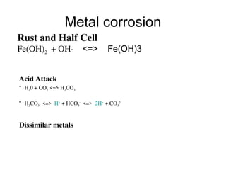
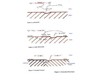
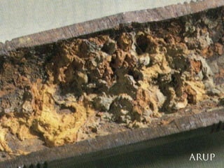
#5 Rust and half cell
Dissolution of metals can also occur when two points on a metal surface have different electrical potentials. These points are termed the anode and cathode. Electrons move from one to the other; at the anode the metal dissolves producing electrons, and at the cathode these electrons are used to form hydroxyl ions. The hydroxide and ferrous ions combine to form ferrous hydroxide. If there is sufficient oxygen present, this hydroxide is further oxidised to form red ferric oxide (rust).
These aqueous corrosion cells occur when the metals or the water are non homogenous. Scale or bacteriological growths can exacerbate this. Blemishes and crevices in the metal surface cause a similar result.
Acid attack
Some waters contain high concentrations of dissolved carbon dioxide. For example; certain ground and mineral waters (such as that supplied for drinking in green bottles by a French sounding company whose name begins with a ‘P’). Under normal conditions this dissolved carbon dioxide is in equilibrium as carbonic acid. However, if the pressure is high enough to prevent the escape of carbon dioxide from the solution, then the chemical equilibrium changes and the solution becomes weakly acidic.
In acid solutions, metals dissolve, displacing free hydrogen ions of the acid so that hydrogen gas forms. At high temperature and pressure, water itself acts as acid releasing hydrogen. Iron from the structure combines with the oxygen to produce a black magnetic iron oxide called magnetite. This is a common feature of condensate systems.
Dissimilar metals
Galvanic corrosion is similar to aqueous corrosion but is caused by joining together metals of different electrochemical potentials. Although this is not primarily a water caused problem, control of the water to reduce its properties as an electrolyte is necessary.
#6 Rust and half cell
Dissolution of metals can also occur when two points on a metal surface have different electrical potentials. These points are termed the anode and cathode. Electrons move from one to the other; at the anode the metal dissolves producing electrons, and at the cathode these electrons are used to form hydroxyl ions. The hydroxide and ferrous ions combine to form ferrous hydroxide. If there is sufficient oxygen present, this hydroxide is further oxidised to form red ferric oxide (rust).
These aqueous corrosion cells occur when the metals or the water are non homogenous. Scale or bacteriological growths can exacerbate this. Blemishes and crevices in the metal surface cause a similar result.
Acid attack
Some waters contain high concentrations of dissolved carbon dioxide. For example; certain ground and mineral waters (such as that supplied for drinking in green bottles by a French sounding company whose name begins with a ‘P’). Under normal conditions this dissolved carbon dioxide is in equilibrium as carbonic acid. However, if the pressure is high enough to prevent the escape of carbon dioxide from the solution, then the chemical equilibrium changes and the solution becomes weakly acidic.
In acid solutions, metals dissolve, displacing free hydrogen ions of the acid so that hydrogen gas forms. At high temperature and pressure, water itself acts as acid releasing hydrogen. Iron from the structure combines with the oxygen to produce a black magnetic iron oxide called magnetite. This is a common feature of condensate systems.
Dissimilar metals
Galvanic corrosion is similar to aqueous corrosion but is caused by joining together metals of different electrochemical potentials. Although this is not primarily a water caused problem, control of the water to reduce its properties as an electrolyte is necessary.
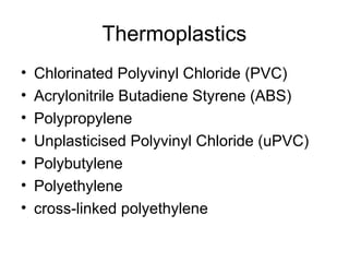
#9 What are we talking about?
The family of thermoplastics covers a range of different materials, which although within the same family group have different properties and subsequently different pressure / temperature ratings, jointing methods, coefficients of expansion etc. a careful check to ensure that system requirements and the material properties correspond cannot be stressed too strongly.
General material properties are as follows;
Chlorinated Polyvinyl Chloride (PVC)
Flexibility and properties depend on the nature and content of plasticisers.
Acrylonitrile Butadiene Styrene (ABS)
Tough, stiff, abrasive and stain resistant compound that can be attacked by chlorinated solvents, concentrated acids and alkalis. Some greases can cause stress cracking. The properties of ABS depend on the proportions of the three constituents compounds Acrylonitrile, Butadiene and Styrene
Polypropylene
Excellent fatigue and chemical resistance properties. Good temperature resistance and useful strength and stiffness. It is attacked by strong oxidising agents.
Unplasticised Polyvinyl Chloride (uPVC)
Hard / tough / strong and stiff with good weathering properties. It is weather resistant and self extinguishing, can be transparent and the surface is scuff and abrasion resistant.
Polybutylene
A polyester compound with good mechanical properties that can be easily moulded with a high resistance to hydrocarbons.
Polyethylene
Tough at low temperatures with excellent chemical resistant properties. Available in low, medium and high density derivations LDPE, MDPE & HDPE, strength and stiffness increasing from LDPE through MDPE to HDPE.
Cross-linked polyethylene
A high density polyethylene compound with improved performance at higher temperatures and pressures.
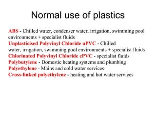
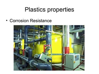
#11 Corrosion Resistance
Thermoplastics being inert and offering superior resistance to a wide range of chemicals over conventional ferrous materials make them an ideal choice as pipework systems to transport and distribute a number of specialist fluids. Recognition of these properties has seen thermoplastics utilised in the process and pharmaceutical industries for the transportation of for example process fluids, ultra-pure water supplies or for drainage / waste pipework.
Some of the corrosion resistance properties of thermoplastics mean they can provide a viable alternative to conventional ferrous materials in HVAC installations where their resistance to corrosion from either the fluid they convey or the environment where they are installed can be beneficial.
Examples;
Swimming pool / pool hall environments
Open circuit condenser water installations
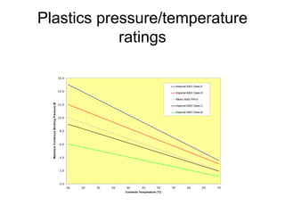
#12 Pressure / Temperature rating
The nominal pressure rating for most thermoplastics is given at an ambient temperature of 20°C, for example a PN10 rated system has a 10 Bar working pressure rating at 20°C.
Temperatures above ambient
Above an ambient temperature of 20°C the pressure rating of the installation has to be de-rated. The pressure / temperature relationship of thermoplastics requires the system pressure rating to be increased until the maximum system temperature of generally has been reached. (Which in the case of uPVC and ABS can be as low as 60 or 70°C).
Thermoplastics have a limited capability to operate above their maximum system temperatures even for short periods of time. Operation above the maximum stated temperature for even short periods of time results in the failure of the installation as the material reaches or exceeds its softening temperature.
Temperatures below ambient
Reductions in the operating temperature unfortunately do not have an opposite affect on the properties of thermoplastics and subsequently do not result in any increase in the system pressure rating. Although ABS & Polypropylene have a wide temperature range this is not the case for all thermoplastics the flexible properties of uPVC at ambient temperatures decrease with temperature making the material brittle and liable to fracture at low temperatures.
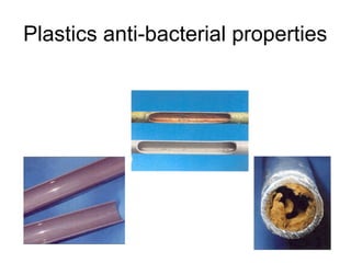
#13 Antibacterial Properties
The clean smooth internal bore and corrosion resistant properties mean thermoplastics assist with the resisting bacterial growth in open and closed systems. The smooth internal surface prevents the accumulation of scale that subsequently denies a site for bacteria and micro organisms to reside and proliferate. The non corrosive properties of the pipework further deny bacteria and micro organisms a source of nutrients.
Although the properties of thermoplastics make life difficult for bacteria and micro organisms to proliferate thermoplastics do not have the same antibacterial properties as copper pipework where the toxicity of copper pipework actively fights the growth of certain bacteria, micro organisms and biofilms.
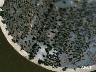
#14 Erosion
Loss of metal or material from the physical structure of the system
Caused by impingement of water, gas or particles removing parts of the affected surface. The solution is to limit the velocity of the fluid.
#15 Heating
Closed water systems can use steel and steel pipe is cheap. Small steel pipes are expensive to install compared to copper or plastic, which are often used for domestic heating systems. Copper can be more easily damaged than steel, hence steel is often used in schools and university halls of residence.
Where steam is available from an energy supply company or in USA, steam is used for heating. Steel pipe is normally used for steam supply but copper light be used for the condensate return.
Where underfloor heating pipes are buried in concrete, it is best to rely on proprietary systems which are normally plastic to resist the effects of external corrosion.
#16 Chilled water
They are closed systems.
Chilled water systems have small temperature rises and therefore require large flow rates to transfer coolth. They use larger size than heating pipes, so steel is normally used
Copper is sometimes used for final connections to cooling coils
Plastic can be used for chilled water and is frequently the choice for buries mains.
#17 Condenser water
Condenser water is called condenser water as it is used to remove the heat from the condensation process of refrigerant circulating in a chiller. The heat is often rejected in a cooling tower, which is normally an open system, but parts can be a closed systems if heat is transferred through heat exchangers. For open systems the normal material choice is galvanised steel. Sometimes thick steel is used based on the principle that the rusting process will take longer than 10 years if there is plenty of steel to rust. Sometimes plastic is used both above ground and buried below ground.
#18 Cold Water Supply
The supply of water for cooking and drinking. The quality of the water varies around the world depending on the water infrastructure of the country. Many water supplies need chlorination to make them suitable for consumption. They generally contain sufficient oxygen to need to resist corrosion. The preferred materials are copper for small sizes, galvanized steel for large sizes and plastic where the water mains are buried.
Steel pipes do provide greater opportunity than copper and plastic for bugs in the incoming water to find places to grow.
Many countries now have a supply of water piped into buildings at sufficient water pressure for there not to be a requirement for storage. On larger buildings storage tanks are required and the opportunity for bugs to grow increases. The cold water systems need to use pipe materials and water circulation design to minimise the time that water remains stationary in pipes and tanks. They also need to be designed to minimise the waste of water due to run off either to get “fresh” water, not stationary in a pipe for a long time getting warm.
#19 Hot water supply
The supply of hot water for washing.
The hot water systems need to use pipe materials and water circulation design to minimise the time that water remains stationary in pipes and tanks. They also need to be designed to minimise the waste of water due to run off so that the consumer gets “hot” water, not stationary in a pipe for a long time getting cold.
#20 Gas
In some developed countries natural gas is available from a gas supply company. The gas is distributed at medium pressure and this pressure is used to overcome the resistance of the pipe so that there is a guaranteed pressure available to the purchaser at the down stream side of the gas meter. This residual guaranteed pressure is used by the consumer to distribute the gas inside the building so that it reaches the boiler gas burner or cookers at their design pressure sometimes allowing for diversity of use of gas consuming equipment.
The gas from the supplier is normally dry and corrosion is not a problem. The preferred materials are copper for small sizes, steel for large sizes and plastic where the gas mains are buried.
Where boilers burners require high gas pressure a gas compressor can be installed. This is bad practice to used electrical energy to raise the pressure of the gas when it could be taken at medium pressure from the supply company.
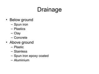
#21 Below ground
Spun iron epoxy coated inside and out
Plastics
Clay
Concrete
Above ground
Plastic
Stainless
Spun iron epoxy coated outside
Aluminium
#22 Watch it
Contractors often offer alternative materials to those specified. It is sometimes the case that they are offering an alternative that is cheaper and performs as well as the pipe work material we have specified. Unless you know the contractor well it is often the case that they are offering a proprietary system that saves the contractor money and does not perform as well as that material we have specified.
Does it have:
Reasonable life?
Reasonable energy consumption?
Reasonable resistance to mechanical damage?
Special tools / joint preparation for plastics
A number of push fit joints require the pipework to be cut square with a special tool to ensure the insert (stiffener) and pipe correctly engage within the fitting. Will a fitter on the 10th floor of a development return to the site office to locate a special tool or will the fitter use the hacksaw in their tool kit?
The cleaning of joints is an essential requirement with the majority of jointing processes for thermoplastic pipework, this doesn’t always translate well to a site environment.
Material shortages
Most cleaning fluid being solvent based evaporate at ambient temperatures, subsequently more cleaning fluid is used than solvent cement as the contents of any open container will disappear. When the fitter on the 10th floor runs out of cleaning fluid with 2 joints remaining to complete his work for the day does he go in search of an additional tin of cleaning fluid?
Push fit fittings consist of a number of components which are required to be assembled in the correct order in order to provide an adequate joint, in a site environment if some of these components are lost the will the fitting be discarded?
Give consideration to the impact of thermal movement on push fit joints and how the thermal expansion and movement expressed by thermoplastic pipework can stress push fit joints.
#24 Circulating Water
Pumped or gravity
Piping arrangements
Pumping arrangements, cavitation, vibration
Pipe sizing, pressure and velocity limitations, fitting resistance
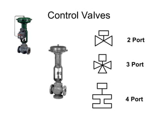
Pipework components and selection
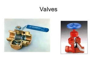
Isolating valves
Regulating valves
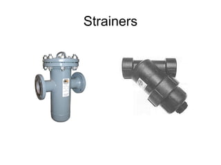
Strainers
Control valves
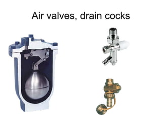
Air vents, drain cocks and sensors
#25 Isolating
It stops the water circulating and should stop water coming out of the end of the pipe for dismantling or maintenance. It has no useful characteristic at intermediate positions. When shut it should be possible to disconnect the terminal units or pipework. Are line size with a flow area the same as the cross section of the pipe in which it is installed. Its function is to stop flow and it does not need a reliable characteristic. It can be a sliding plate that is driven into a wedged seating or a circular plate that rotates from being in line with the flow to being across the flow driven into gasket material like neoprene to provide an interference fit. Pressure and temperature rating of the valve will decide if it is screwed or flanged and what types of water seals are used.
Regulating
It regulates the flow. At an intermediate position it has a know characteristic for flow against pressure drop. The characteristic can be helpful by providing high pressure drop at small flows over a large part of the valve opening. This is a logarithmic characteristic.
Are selected for an appropriate characteristic such that the flow rate through them can be adjusted with similar steps in flow rate change with valve adjustment. That is a turn at the beginning of valve closure giving similar flow rate changes as a turn towards the end of valve closure. Some regulation valves are nearer to isolating valves and need to be linked to orifice plates for flow measurement. Others have such good characteristics that their position can be calculated and set, achieving a system balance without commissioning adjustment and measurement. Double regulating valves are used for balancing and have a very good characteristic and an orifice plate in one valve body.
#26 Strainers
Take the dross out of the water circuits. At commissioning they will remove welding swarf, flux and dirt. Finer strainer mess is sometimes used during commissioning which should be removed after commissioning to reduce pressure loss. Isolating valves are required up and down stream of each strainer. Some strainers have a change over strainer basket so that either basket can be cleaned without the need for isolating valves.
Contain perforated or wire mesh baskets through which the water must flow. They are used to remove swarf and dirt from a system. The size of the of the basket should ]be large enough so that the area of flow through the perforations is the approximately the same as the pipe cross sectional area. Some times two baskets are provided; one with a finer mesh for flushing and cleaning which is removed after commissioning and the other left in for normal operation.
In systems that might often become dirty two strainer baskets are arranged as a duplex pair of strainer baskets so that either can be removed with the other in service.
#27 Air bottles and valves
All pipe systems we install are full of air when they are installed and this air needs to be removed as part of the commissioning. They can be manual or automatic as the designer chooses depending on location. During the operation of circulation of water the chemical and biological processes produce gas that also has to be removed. Permanent air vents at the top of pipe systems are an essential part of gas removal.
When systems are filled with water the air or gas is produced during normal operation, they need to be released or the system does not transfer heat or coolth efficiently and make noise. As small air and gas bubbles are carried along in the water, an air bottle is necessary to collecting the air before it is released by the air vent. Air vents can be automatic so that gas is released during normal operation. If an automatic air vent is placed in part of a system below atmospheric pressure it will let in air rather than let air out.
Drain cocks
These are required at all low points for use during commissioning for draining away the dirty water after flushing. They are also needed for draining sections of the system for alterations during the life of the building
Drain cocks are used during flushing and cleaning and for draining down the system during alternations and maintenance. As dirt is carried along in the water a dirt pocket for flushing and cleaning should be provided at low points with a drain cock the same size as the pipe. An isolating valve is frequently used. A drain cock should be provided in sections of the system to drain down that section between isolating valves. This can be sized smaller than the pipework in which it is installed.
#28 Gravity circulation of water was used before pumps were available. It has been replaced by pumped circulation to save money through smaller pipework and easier installation and achieve greater flexibility for installation. Even with the current requirement to reduce carbon dioxide emissions, gravity circulation is unlikely to be used. The important thing is that gravity circulation will occur in all pumped systems and can cause problems if ignored.
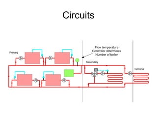
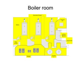
Primary circuits contain the main thermal plant such as boilers and chillers. The object is to enable the plant to operate efficiently, safely and in a commissionable and maintainable way. Boilers have different requirements to chillers as boilers can waste heat when off if heating water circulates through them. This is known as standing losses. Chillers do not suffer from standing losses. They require design to avoid mixing of return water with flow water from non operating units and they do not like variable water flow which causes instability in the chiller control and at worst freezing of the evaporator.
Secondary circuits contain pumps and control valves to allow circuits to be separately operated and or have the temperatures changed. They deliver the temperature and low rate required by the terminals. Where the terminal flows and temperatures can be matched to the thermal producers a common primary and secondary circuit can be used. The selection of the number of secondary circuits requires an understanding of the temperatures required by the terminals and the likely times of use of the circuit so that pumping is not consuming energy when the circuit could be switched off.
Terminal circuits contain the final heat exchange element, control, valves and local pipe accessories. The circuits are selected to maintain the temperatures required, ease of commissioning and maintenance.
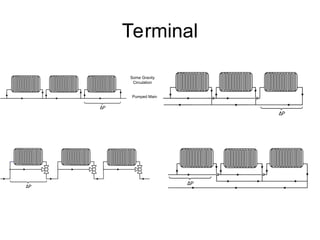
#29 Parallel
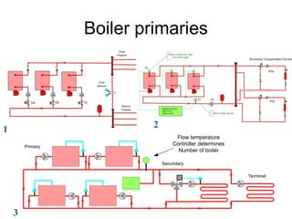
Diagram 1. The flow temperature from the boilers is the correct temperature for the terminal units, so there is no need for a secondary circuit. The boilers include isolating valves so that there are no standing losses. The terminal units need to be variable flow or the three boilers will always be on and running inefficiently on part load with standing losses.
Diagram 2. The flow temperature from the boilers is correct for the terminal units at maximum but as the load reduces the return water flows through the off boilers and a lower mixed flow temperature is achieved. Is this hot enough for the terminal units? If the terminal unit is heating outside air and the heat gains in the rooms is high enough for the demand to be reduced then it will not be hot enough. If the terminal units are in the space then it will be hot enough.
Series
Diagram 3. The secondary circuits are a mixture of variable flow and constant flow. Each boiler comes complete with its own pump and bypass. Only the first boiler in the series gets the coldest water. If you want condensation then this is not as good as parallel circuits
#30 Parallel
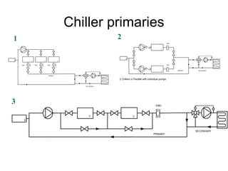
Diagram 1. A traditional solution. A common pump feeding all three. Without isolating valves on each chiller there will be mixing of the water passing through the chillers that are off with the water through the chiller that is on. If the chillers are controlled by their own flow sensor the temperature in the main flow will rise above the design temperature and there will be an inability to control RH from dew point if that is important. If the sensor is in the common flow the chiller that is on will need to produce a lower temperature than the design flow temperature for the plant and it may freeze. If the chillers are isolated the flow rate through each chiller will increase as the pump rides up its characteristic curve. It is not very stable
Diagram 2. If each chiller has its own pump then the flow rates through each chiller will not vary much and each chiller can have its own sensor in the chiller flow. The decision on how many chillers needs to be made on the flow rate demands of the secondary circuit by putting an orifice plate in the chiller ring main.
Series
With series flow the sensor location in each chiller will decide the sequencing of the chillers. The first chiller will increase its output as the demand increases until it cannot meet the demand when the second will start to load up to achieve the design temperature. If both sensors are located downstream of the last chiller in the series then both chillers will ramp up together.
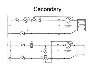
#31 Variable flow primary
This achieves less pump energy in the primary circuit. The complication is that the two port control valve needs to have enough “authority” to control the primary circuit.
Constant flow primary
More pump energy but much more stable flows and stable primary plant. Lower resistance due to lower pressure drop through three way valve.
#32 Series gravity
Used for radiator circuits with manual control. A manual open valve has very little pressure drop and gravity circulation will usefully circulate the heating water through the radiator. Only one pipe is required to run around a building. The length of pipe is reduced.
Parallel
Used extensively for heating and chilled water supplies. The requirement is that the pump is sized for the furthest index circuit and all the others have to be balanced to achieve the correct flow rate at the same pressure drop using a regulating valve.
Series three way valve
Used extensively in Europe. Only one pipe is required to run around a building. The length of pipe is reduced. The three way valve is normally thermostatic
Parallel reverse return
More pipework and all terminal units are the index unit. It is almost self balancing
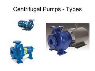
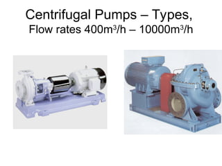
#33 Horizontal
single stage
end suction for
hot and cold water systems
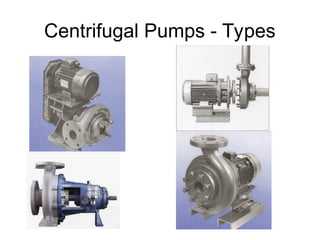
#34 Belt driven end suction single Stage
Direct driven end suction closed couple
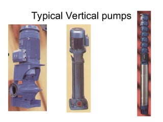
#35 Single stage vertical, saves plantroom space, allow for provision of lifting the motor.
Multi stage vertical, for high pressure systems e.g. steam boiler feed pumps.
Submersible motor pump for deep well (borehole) application.
#36 Direct drive with coupling, end suction, single Stage
Direct derive with coupling, axially split, double suction, single Stage
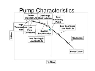
#37 Pump characteristics
Same pump with different impellers
Efficiency
hydraulic, mechanical, electrical
Power
NPSH Pump Characteristics
-influence of SG on motor power
-influence of viscosity on motor power and on pump curve
-pumps working in parallel / series
-minimum flow / maximum flow
-best efficiency zone
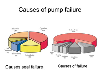
#39 Common operational causes:
not at BEP
insufficient NPSH
operating dead-headed
dry-running
improper venting
Common mechanical causes:
shaft alignment
coupling balance
pipe strain
Common design causes:
flush arrangement
insufficient cooling
seal auxiliaries
#40 Let by % of max flow or Leakage
Max Pd
PN Rating
Kv = Kv p
Rangeability
Inherent Characteristic
Linear
Power linear
Equal percentage
Modified parabolic
Quick opening.
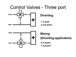
#41 Most valves like to have two in and one out. If they are this type and piped for one in and two out they will bounce as the valve nears its seat.
Some valves are designed for one in and two out. A rotating shoe type is an example.
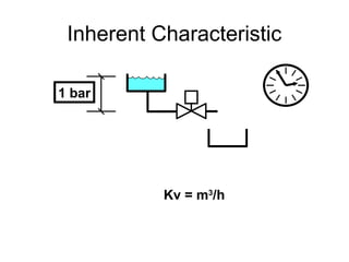
#42 At a constant pressure drop across the valve it will produce a flow that varies with the inherent characteristic of the valve seating.
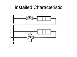
#43 The heat output or input at the terminal varies in a non linear way with the flow of water. With constant pressure drop across a control valve the inherent valve characteristic needs to provide a non linear change in flow to attempt to get a linear relationship between control motor position and heat out put or input from the terminal.
Installed the pressures change in the circuit as the flows change and the pump operating point changes. The pressure drop across the valve changes so the characteristic of the valve changes both with its inherent characteristic and the system characteristic.
This is white three way valves are used as the system characteristic is largely removed as the total flow is nearly constant.
To save energy we like to vary the flow and consequently the valve characteristic needs to compensate for non linear heat output and input and system pressure variations.
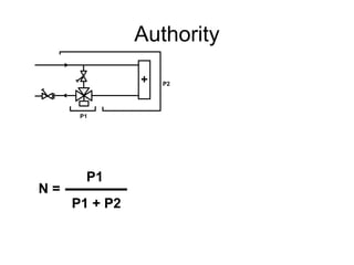
#44 P1 = valve pressure drop at coil design flow
P1 + P2 = available pressure for final circuit
Course work:
If the pressure drop across the terminal unit P2 = 20 kPa @ 5 litres/s, what size of control valve do we use?
The manufacturer will specify a range of authorities for the valve. Assume they require an authority of 30%, which valve do we select from the valve sizing chart?
What size should the bypass balancing valve be? How do you achieve the correct setting for the bypass valve?
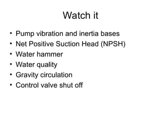
#47 Watch it
Pump Inertia base
Net Positive Suction Head (NPSH)
How much is available (varies between pumps / manufacturers)
All losses between sump and pump inlet
Water vapour pressure (increases with temperature)
Cavitation
Water hammer
Water quality
Gravity circulation
Control valve shut off
Sensors
Pressure and temperature need to be measured in the circulating water. Sensors should also be removable for replacement and calibration. They can be installed through self sealing plugs and “gauge cocks” that allow the sensor to be removed without draining down the pipe.
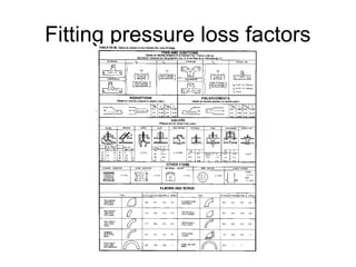
#48 “Handbook of Hydraulic Resistance” by Idelchik
#49 Steam and condensate
Compressed Air
Underground buried
Swimming pools
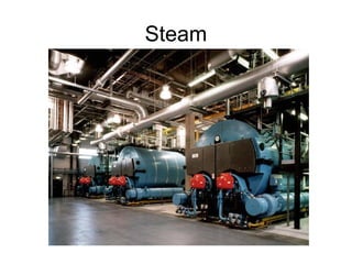
#50 Steam Pipework
There are 3 main aims to achieve in the design of a steam distribution system:
Low pressure drop between generation and point of use
Minimal heat loss from the distribution system
No condensate in the steam at point of use (i.e. dry steam)
Design Criteria
Steam pipework should be designed based on pressure drop
or maximum velocities.
Max. velocity in main runs 25-30 m/s (40m/s at a push)
Max. velocity in branches 15-20 m/s
Total pressure drop from generation to point of use < 10%
Pipework Routing
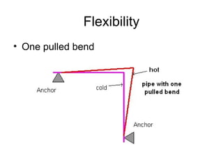
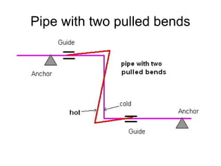
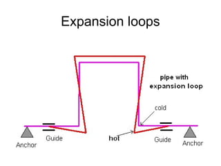
The distribution system must be designed considering thermal expansion (see relevant sections on thermal expansion, anchoring, guiding, expansion loops etc)
Pipework should be run at a fall (minimum 1:100) to minimise water hammer and to facilitate draining down in case of condensation
All pipework should be Colour coded/ marked as per BS 1710
All bends should be long radius to reduce pressure drops
Take-offs
All take-offs from steam pipework must be from the top of the pipe to prevent condensate entering the branches
Take-off legs should have drains at the bottom just in case any condensate accumulates
A steam separator is usually installed after the boiler to achieve the required steam dryness – typically 98% from boilers and 99.9% after separator
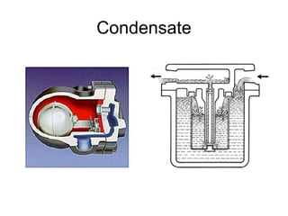
#51 Condensate Pipework
Condensate is formed from the steam after it has given up its thermal energy
Traps are provided along distribution mains and after terminals to stop steam flowing through without giving up its latent heat and to let condensate pass into the condensate return pipework for eventual return to the boiler.
There are 2 main aims to achieve in the design of a condensate distribution system:
Reasonable pressure drop between point of use and the boiler.
Minimal loss of condensate through leakage and inability to get condensate back into the condensate system. There is little pressure available to drive the condensate back along the pipe or to drive it vertically upwards. Condensate pipework is mainly designed to run full under gravity with steam driven lifting pumps where vertical rise is essential.
Design Criteria
Condensate pipework should be designed based on pressure drop
or maximum velocities the same as heating pipework.
Max. velocity 1.5 m/s
Max. pressure drop 200 Pa/m
Pipework Routing
The distribution system must be designed considering thermal expansion
Pipework should be run at a fall (minimum 1:100) to facilitate return under gravity
All pipework should be Colour coded/ marked as it is very hot
All bends should be long radius to reduce pressure drops
Take-offs
All entries into condensate pipework should be from the top or side of the pipe.
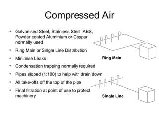
#52 Compressed Air Pipework
There are 3 main aims to achieve in the design of a compressed air distribution system:
Low pressure drop between generation and point of use
Minimal leakage from the distribution system
No condensation in the air at point of use (i.e. dry air)
Design Criteria
Compressed air pipework should be designed based on pressure drop
or maximum velocities.
Max. velocity in main runs 6 m/s
Max. velocity in branches 5 m/s
Pressure drop from generation to point of use
(excluding final attachment i.e. hose) 0.1 bar
Total pressure drop from generation to point of use
(including final attachment) < 10%
Pipework Routing
There are 2 main routing layouts:
Ring main
This is the preferred routing for compressed air systems as it allows
Sections of pipework to be isolated whilst keeping the rest of the system ‘live’
Reduced velocities in the pipework
Single line distribution
This is used when only one or two points of use are required. It is a cheaper and easier solution than the ring main but doesn’t allow the flexibility of a ring main.
General Considerations:
The distribution system must be designed considering thermal expansion (see relevant sections on thermal expansion, anchoring, guiding, expansion loops etc)
Pipework should be run at a fall (minimum 1:100) to facilitate draining down in case of condensation
All pipework should be Colour coded/ marked as per BS 1710
All bends should be long radius to reduce pressure drops
Take-offs
All take-offs from compressed air pipework should be from the top of the pipe to prevent condensation entering the branches
Take-off legs should have drains at the bottom just in case any condensation does occur
Filtration/ separation should be considered at point of use to prevent damage to the final machinery from dust/ shedding pipes/ oil/ jointing solvents etc
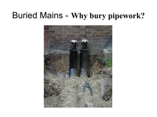
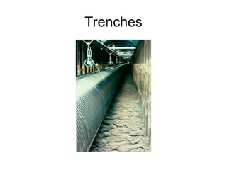
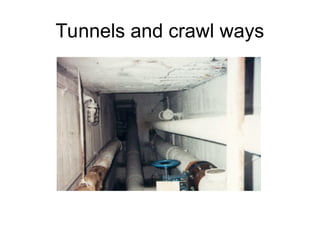
#53 Why bury pipework?
Pipes are buried in the ground for some of the following reasons:
- To conceal the pipes.
- To reduce heat losses, including possible freezing – the ground remains at a more or less constant temperature, reducing heat losses.
- For spatial logistical reasons – there may be no space above ground for the pipes.
- For economic reasons – putting the pipes below ground removes the need for expensive concrete protecting ducts.
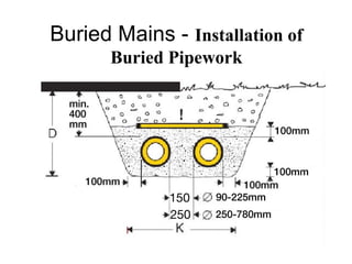
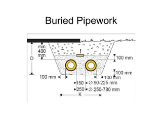
#54 Installation of a typical LTHW system:
The depth of the trench is related to the diameter of the pipes.
The pipes are laid on a 100mm bed of sand, up to 250mm apart and with a clearance of 100mm from the trench walls.
The trench is then backfilled with sand to a depth of 100mm above the pipes.
Warning indicator tapes are placed above the sand over both the flow and return pipes.
Where possible pipes should be 400mm below the surface.
The remaining trench is then filled using good quality backfill material.
In soft areas the last 100-150mm should be seeded top soil.
The minimum cover depth from the surface of the pipes should be no less than 400mm.
In areas of heavy traffic a hard standing layer or road surface should be added in addition to the 400mm of cover.
For pipe sizes of greater than 450mm nominal diameter, the depth of cover will be greater than 400mm and is particular to each pipe size.
Where the cover is less than the recommended minimum cover depth, protection such as concrete slabs should be placed over the compacted sand layer to protect the pipes from gardening forks etc. In areas of hard standing reinforced concrete should be laid over the sand or reduced backfill layer.
The depth of the sand layers should not be compromised.
Prior to doing any digging the area should be surveyed using pipe and cable locators and through the use of test holes. It should be noted that conventional pipe and cable locators do not detect plastic pipes or other non metallic apparatus unless tracer wires or signal transmitters are present.
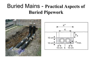
#55 Expansion
In a bonded pipe system there will be movement between the outer casing and the sand. This movement should be absorbed using a sand pad a bends and branches. To allow the pipe sufficient movement the normal trench width K should be increased to K+ in the expansion zone. Whilst compression of the backfill layer can be simply as required (Pa), there is a limit to the amount of compression (Pmax) that should be applied to the sand layer.
If it is necessary to restrict the movements of sections of the pipe, anchor blocks can be used. These consist of puddle flanges which attach the pipes to concrete blocks.
Expansion joints are available where expansion movements is not possible to absorb the temperature induced stresses in the steel pipe. These operate once only.
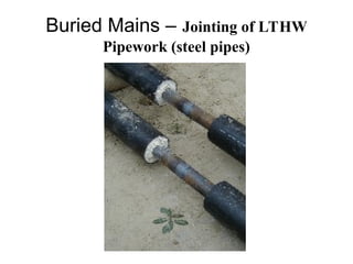
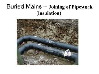
#56 Jointing of LTHW pipework.
LTHW pipes are cut to length and welded in place on site. Usually 10% of the welds are NDT (Non destructively tested) tested using ultra sound.
#57 Jointing of LTHW pipework.
When pre-insulated pipes are cut to length the insulation layers must also be cut back to avoid heat damage from the welding. Once the steel pipe sections have been welded and tested, then a band muff is fusion welded around the joint and the resulting void is then filled with the same insulating material as that supplied with the pipe. Every one of the fusion welds should be pressure tested.
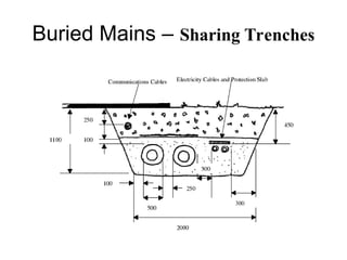
#58 Buried Mains – Sharing Trenches
Buried mains often have to share trenches with other services such as power, gas and communications.
Power cables should be located a minimum of 300mm away from buried mains to minimise the inductive effects on pipe leak detection systems in use.
Other services should be located a minimum of 250mm away.
Communication cables can be laid straight in the trenches or ducts with pulling wires can be laid for the future addition of communication cables. The addition of ‘dormant’ cables to open trenches to cater for future capacity should be considered as the use of chambers can then be avoided.
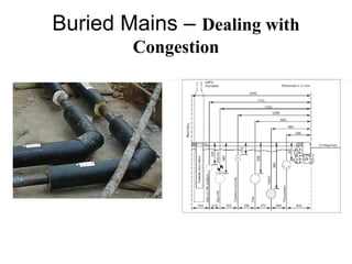
#59 Dealing with Congestion
Ideally buried mains are placed in the footway however where the footway is very congested with services it may be necessary to place buried mains in the carriageway.
District heating pipes are generally laid in trenches such that all air naturally vents to a building riser. For this reason pipe ‘loops’ to get around existing services etc are avoided as automatic air vents (aav’s) would be required, which would in turn require maintenance chambers. AAV’s are unreliable and prone to leakage. The ‘loops’ would require an extra 8 bends and at least 10 extra welds per flow and return ‘loop’ which would add considerably to the installation cost.
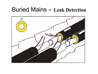
#60 Leak Detection
Some pre-insulated pipe systems include embedded surveillance systems which allow continuous monitoring of the system. Leaks can be detected and their location pin pointed to the nearest metre or so. Strictly speaking the alarm system is accurate to 1% of the length of pipe work tested. The central system monitor will locate the sector with the leak, thereafter tests from each alarm point in the sector will narrow down the search. Alarm points are normally located at building entries or every 250m or so on a long run.
It should be noted that surveillance system does not prevent corrosion, but indicates the presence of moisture in the insulation, making repairs possible before serious damage has occurred. The system consists of embedded copper wires and hydroscopic felt pads. A fault signal is transmitted if the moisture level in the pads exceeds a given limit or the copper wire is broken.
Buried mains pipes generally have a design life of 30 years. Provided the relevant corrosion inhibitors are used and the pressure and temperature limits are not exceeded, maintenance is usually limited to turning the valves once or twice a year.
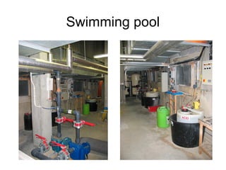
#61 Pool Water Pipework
Circulation, filtration, and disinfection pool water pipework is normally the direct responsibility of a pool water specialist supplier/installer. Particular care is needed in choice of materials for pipework and fittings due to the corrosive properties of the chemicals used for the pool water treatment. It can generally be considered in two particular areas, pool water circulation pipework and chemical dosing pipework.
Circulation and dosing pipework
Material should be uPVC with solvent weld fittings with stub flanges complete with mild steel backing rings at all connections to valves, pumps, strainers and filters.
Dosing Pipework
Should be installed within protective sleeves or pipes where there is risk of physical damage or risk of damage to people or property as a result of pipe fracture. Protective pipes should be designed to drain freely so that any leakage returns to the chemical bund area or similar safe collection point. The use of sharp right-angle bends should be avoided to reduce erosion by use of long swept right-angled bends.
Each separate chemical treatment system has a completely independent pipework system installed and labelled to minimise the risk of any mixing of incompatible chemicals during operation, maintenance or chemical deliveries.
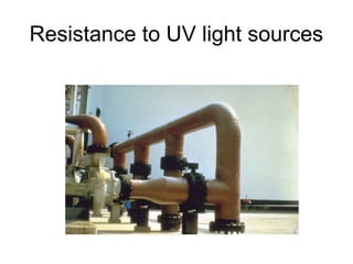
#62 Resistance to UV light sources
Many thermoplastic materials are not tolerant to prolonged exposure to ultraviolet light sources resulting in discolouration and embrittlement. Thermoplastic materials should not be stored externally, storage, under a shelter (for example a covered pipe rack) or covered with a tarpaulin being the preference where internal storage cannot be provided.
Externally installed pipework that is not thermally insulated will suffer degradation due to exposure to ultra violet light, the service life of such installations can be extended by painting the installation. Care should be taken and manufacturers advice sought when selecting paint and generating a painting specification to ensure that the painting the pipework when it in itself not detrimental to the pipework installation.
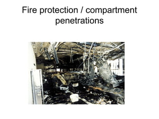
#63 Fire protection / compartment penetrations
Not having the same integrity or stability as traditional ferrous materials requires thermoplastic pipe penetrations to be sealed with intumescent sleeves where fire compartments are penetrated to maintain the integrity of the fire compartment.
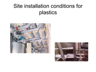
#64 Site installation considerations
The use of solvent weld fittings for a number of thermoplastic products although needing to be undertaken in a well ventilated areas provides a heat free jointing process which can be useful when considering larger pipework sizes that would require traditional ferrous materials to be either rolled grooved, brazed welded or silver soldered.
The fact that large diameter pipes can be jointed without a heat source means the pipework can be installed without a hot works permit or in a areas where hot works are not allowed and space restraints prevent fabricated assemblies being manoeuvred and subsequently installed.
#65 Watch it
Special systems are often designed by proprietary installers. Beware becoming responsible for their design work, whilst maintaining sufficient understanding to know when they are making a mistake.
#68 Sizing pipes requires a balance of aims. Lowest installation cost, reasonable running cost, ease of commissioning, reasonable service life. High velocities can reduce service life through erosion but velocities have to be very high for this to occur. Erosion in straight pipes is far less than erosion at bends. For example very high velocities in equipment bypass pipes are acceptable if there are no bends.
At the current cost of electricity the traditional pressure drop rate for sizing pipes should be much higher. E.g. pipes should be smaller with larger pumps. Ref 1. With the current requirement to reduce carbon emissions, I support continuing to keep normal pipe sizing pressure drop rates low and pump energy low. This is supported by many building codes.
Heating sizing steps through space loads to terminals to pipes to boilers to gas demand
DT (1) is the temperature difference between the inside air temperature and the outside air temperature.
DT (2) is the temperature difference between the water temperature in the terminal heater and the inside air temperature.
DT (3) is the temperature difference between the water flow and the water return around the system.
DT (4) is the temperature difference between the combustion gases and the water in the boiler.
h (1) is the heat transfer coefficient particular to the heat emitter.
h (2) is the heat transfer coefficient particular to the boiler heat exchange.
SH is the specific heat of water at the temperature of the heating water
A (1) is the area of each element of the fabric.
A (2) is the area of the heat emitter (radiator/ natural convector).
A (3) is the area of the heat exchanger surface within the boiler.
Vol is the volume of the space being heated.
V (1) is the volume flow rate of the heating water
EFF is the efficiency of the boiler.
V (2) is the volume flow rate of the gas.
CV is the calorific value of the gas.
#69 Sizing criteria are normally based on keeping the water flow velocity sufficiently low to limit erosion of the pipework and sufficiently high to help air purging of the system
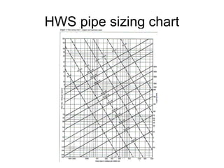
#70 This shows recommended pressure drops for constant volume systems operating for 8000 and 4000 hours per year. It should be noted that the drops recommended are for a system's index run. All other pipes should be sized to optimise the use of available pump head.
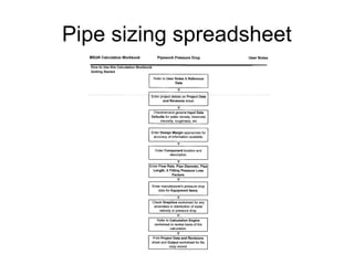
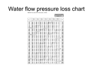
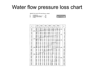
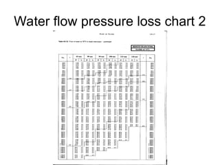
#71 Pipe sizing spreadsheet
MSSN/Technical/Design and technical guidance/model calculations and calculations plan/pipework pressure drop
#72 PIPE SIZING
Preliminary size:
Choose a temperature drop across the system. Assume temperature drop to be the same throughout the system, calculate the mass flow rate in each pipe section. Choose a typical ‘economic design parameter’ and size each section using pipe sizing tables for the appropriate pipe material and fluid temperature.
This is the preliminary sizing procedure, based on two assumptions:
any circuit could be the index circuit
constant temperature difference
Finally size using the pressure available in the none index circuits and the terminal heat exchange temperatures required.
Design parameters
Maximum water velocities (regardless of water temperature) Pipe diameter (mm) Up to 50 - 3 m/s. 50 to 150 - 6m/s Above 150 - 8m/s
Initial pressure drop for establishing index circuit:
Around 300 within 100 – 600N/m²
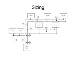
#73 EXERCISE
Water flow and return temperatures 82°C and 71°C.
Specific heat capacity of water, 4.2 kJ/kg K.
Use the fitting data in the schedule
Assume the boiler resistance is 50 kPa at your required flow rate.
Assume terminal resistance 25kPa at your required flow rate.
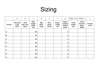
The schematic drawing represents a LTHW 2 pipe heating system supplying a number of buildings. The kW loads shown on the schematic represent the calculated heat loss from each of the buildings. Using the pipe sizing data sheets provided.
State the parameters that you are to use when sizing the pipe work.
Calculate the mass flow rates required for the system.
Size all the pipe work sections.
State the required pump duty in Kg/s and kPa.
Identify the calculation the index circuit and explain its significance.
Calculate each resistance necessary to achieve a hydraulic balance and position on the schematic.
Given that this is a preliminary pipe sizing procedure, what changes might we expect to see in the final sizing results and why?
#78 References
Arup HVAC application guide
MSSN Model calculations
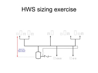
#79 HWS sizing exercise
This exercise covers the principle of “demand unit” sizing which is used in Cold Water and Compressed air pipe sizing. Hot water is generated close to outlets where the hot water is used.
Water supply company guarantee a pressure of 2 Bar at the entry to the building.
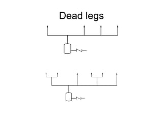
#80 Dead legs
If the Hot Water supply pipes feeding the points of use are allowed to get cold then a lot of water is wasted waiting for the hot water to be delivered.
Many countries have maximum lengths of pipe that are allowed to get cold. These are sometimes called dead legs as the water can stay in them for a long time before the point is used.
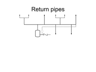
#81 Return pipes
Where the distribution pipes are longer than the maximum dead legs a return pipe is provided at the maximum dead leg distance so that the distribution pipe is kept hot by circulation from the Calorifier. The return pipe heating system is normally driven by a pump but they can be designed to operate under gravity circulation.
#82 HWS sizing exercise
Assume the following rates of discharge to give an adequate service in each sanitary fitting
From the diagramme there are 5 of each fitting.
If each of the fittings were assumed to require a pipe that would supply all of the fittings at the required flow rate all at the same time the flow rate in the first pipe of the calorifier would be:
It is not appropriate to assume that all fittings will be operated simultaneously.
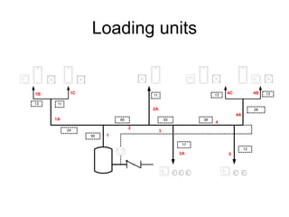
#83 Loading units
Some times called demand units.
A water supply distribution system is accepted to have a diverse use. Not all the fittings will be on at the same time nor will they demand the maximum flow rate. To assess how much each pipe can diversify its design flow rate loading units are allocated to each fittings
Using this data the total loading units are:
The loading units are converted to a flow rate using the following formulae developed from probability:
Loading units > 30 Q = Loading Units0.718 x 0.0465
Loading units < 30 Q = Loading Units0.585 x 0.078
Therefore the flow rate for the first pipe of the calorifier is 1 l/s
Each section of pipe feeding two or more fittings is sized on these demand unit flow rates.
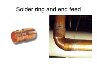
#87 Screwed, welding, grooved, brazing, compression, solder ring, end feed solder, crimping, push fit.
Clip, drop rods, bearer, roller, shoe, guide, anchor, seismic hanger. Buried.
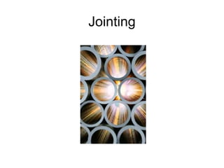
#88 Pipes come in lengths manageable for transportation
Steel pipes can be as long as the delivery lorry and some plastic pipes can be as long as the largest coil that can be put on the back of a lorry.
They do have to be joined together and to pieces of plant.
Changes of direction can sometimes be accommodated by bending the pipe using its inherent flexibility but this has a high labour cost and takes space. Jointing therefore occurs at changes of direction and branching of the pipe.
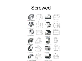
Screwed
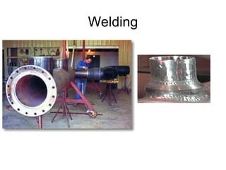
Welding
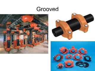
Grooved
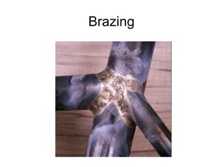
Brazing
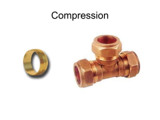
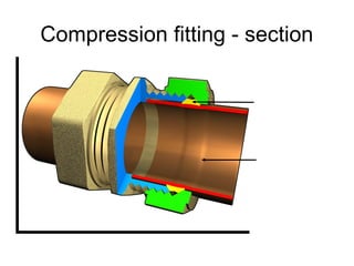
Compression
Solder
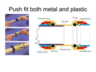
Push fit
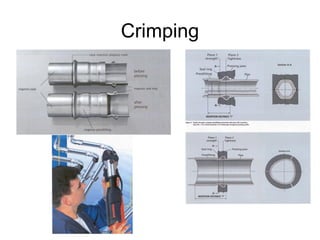
Crimping
#89 Normally used for steel pipes. There are parallel threads and tapered threads. Parallel threads are normally used for joining pipe sections together as the threads get progressively tighter. Parallel threads are used with washers to make a joint water tight by compressing the washer.
#90 Welding is used for large steel pipe sizes and for high pressures. Only skilled welders can produce a good weld. They need to be trained and need to show welding certificates appropriate to the quality of welding required. Where we have agreed to site inspections it is always worth checking the welding early in the contract when the HVAC contractor appears on site.
Good contractors will have their own welding quality control and each welder will have to produce good test welds. Not so good contractors will let inexperienced welders start on installing pipework. Any welds that look of low quality should be inspected by an engineer experienced in welding. On projects where welding is used for jointing the specification should require tests of welding which progressively require more and more welds to be tested, normally electrographically, should weld fail. You should chose the worse welds for testing as soon as the contractor has completed say ten welds.
#91 There are proprietary system of pipe jointing for steel pipes referred to as grooved joints. Each pipe length includes a groove in it around the circumference close to the end of the pipe. A two section clamp is then applied to the pipe that includes a neoprene joint that is compressed to make the whole joint water tight.
Grooved joints are frequently used for CWS, sprinkler systems and fire risers as they are not subject to a much of thermal expansion.
#92 Brazing is the joining of metals through the use of heat and a filler metal – one whose melting temperature is above 840°F(450°C) but below the melting point of the metals being joined. On non- ferrous metals, the tensile strength of a properly made joint will often exceed that of the metals joined. There is seldom any need for grinding, filing or mechanical finishing after the joint is completed. Brazing is performed at relatively low temperatures, reducing the possibility of warping, overheating or melting the metals being joined. Brazing is frequently used for jointing large copper pipes.
#93 A compression fitting is a type of coupling used to connect two pipes or a pipe to a fixture or valve. It consists of three parts... the compression nut, the compression ring, and the compression seat. The nut is slid onto the pipe, followed by the compression ring. The pipe is slid into the fitting and the nut is tightened down. As the nut is tightened, the compression ring is pressed into the seat, causing it to compress against the pipe and the compression nut, providing a watertight connection. Compression fittings are normally used for copper pipes.
#96 Copper pipe can be easily jointed using solder and a suitable flux. Solder ring fittings include the solder in the fitting. End feed fittings are cheaper as the solder has to be fed into the end of the fitting. Beware that too much flux can result in problems of pipe corrosion.
#97 Push-type fittings have a serrated retaining grab-ring which prevents withdrawal of tube from the fitting in normal service. Plastics seals are incorporated at each opening of a fitting. The tube may be released by forward disturbance of the grab-ring by the use of a special tool and the joint may be subsequently reassembled.
Tube sizes from 10mm to 54mm can be accommodated in push-fit systems.
Push-fit systems are not suitable for gas services because of the possible deterioration of the EDPM sealing ring under the action of natural gas.It is felt that, as a safety measure, use in waste systems is not recommended due to pipe surface indentation by the grab-ring. Tubing assemblies must be truly aligned. Push-type systems are intended for use with copper, light gauge stainless steel tube and cross-linked polyethylene for installations conveying hot water supply, cold water supply and compressed air.
It is essential that there is adequate space to make the joint such that it is properly aligned.
#98 Crimping is a a system of jointing were the fitting and the tube are deformed by a crimping tool under high mechanical pressure to make a water or gas tight joint.
Press-fit joints are made with the use of a jawed circumferential compression tool or a tool utilizing press slings for copper tube 42mm size and above. There is a limitation to tube sizes. Steel pipe has to be thin. The cost of press-fit pipe fittings is greater than that of traditional screwed or welding fittings but it is very fast to install.
Tube sizes from 10 mm to 108mm may be jointed in this manner. Work should be limited to safe, accessible installations for operatives. The installations needs to be managed to ensure that all joints are properly completed and recorded.
It is essential that installers be selected only from companies and operatives who have previous successful experience with the jointing systems.
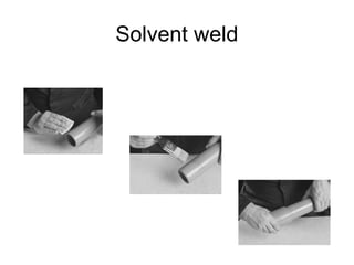
#99 Solvent Weld
The solvent cement operates by chemically softening the joint surfaces. Joint integrity will be greatly reduced if these surfaces are not clean and properly prepared.
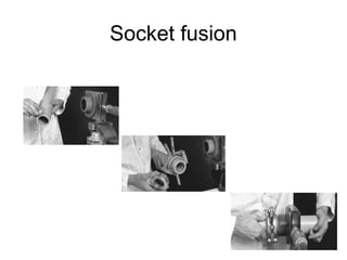
#100 Socket Fusion
Socket welding involves fusing of pipe end and fitting through the application of heat, using specialist equipment. Welding equipment comprises of heating surfaces applied simultaneously to pipe end and fitting. The pipe end is inserted into the fitting, bringing the two melt surfaces into contact which combine to produce a homogeneous joint upon cooling. The joint is end thrust resistant and designed to exceed the performance of the pipe with regard to the pressure rating.
#102 The word 'brackets', although commonly used, is misleading as an inclusive term and should be superseded in this respect by the term ‘pipe fixings’.
#103 The following requirements are applicable to all pipe fixings:-
They must be strong enough to carry the maximum loads to which they will be subjected. These loads may be caused by operating stresses in the completed system or by ‘shock’ loads imposed during pipeline erection.
They must not weaken the structure to which they are attached.
They must be easy to erect with the minimum number of operations between initial setting out and final adjustment. They should be suitable for erection in advance of pipeline fabrication, thus obviating the need for temporary slings, struts, etc.
They should be so designed that they do not impede the erection of pipes.
They should not encourage corrosion, e.g. by harbouring water or by electrolytic action when supporting non-ferrous piping.
Appearance must be appropriate to surroundings. Neatness and finish are important on exposed pipe work in commercial, educational and domestic buildings, whilst in industrial premises and on concealed pipes functional efficiency is all that is required.
They must be the cheapest possible and readily available.
Components must as far as possible be capable of standardisation and be so designed that they can be easily constructed, preferably without heat, from materials which are readily available in quantity for stock or for quick delivery to meet local emergencies.
The following additional requirements are dictated by local conditions and operating characteristics of particular services:-
If it is essential for pipes to be laid to falls for venting or draining, fixings should provide means of minor adjustment of levels after installation.
Fixings must allow for expansion movement in the piping.
Where pipes are subjected to unusual vibration or shock, means should be provided for preventing the pipe from becoming dislodged from its fixings.
For insulated piping, if the specification calls for maximum continuity of lagging finish, e.g. as on external weatherproofed lines of for maximum heat conservation, moving components should not cause displacement of the lagging surface.
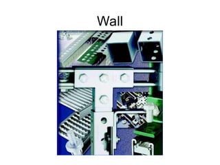
#104 Wall
Ragbolt is a bolt having one end flattened and barbed to key into cement used in building it into brick or concrete.
Expansion bolt of which there are several proprietary designs, e.g. the ‘Rawbolt’ for securing to brick or concrete. Most makes operate on the principle that tightening action on the bolt expands a metal sheathing or other shape to secure the bolt in a suitably drilled hole.
Bracket referring to a fabricated steel cantilevered bearer prepared for attachment to steelwork, brick or concrete and drilled or otherwise prepared to support a pipe from underneath.
Concrete Insert may be steel or cast channel section, or slotted square section, usually of proprietary make, with provision for keying into concrete. Inserts are positioned in shuttering ready to receive a bolted attachment later without the need for cutting away. A slotted strip, angle or patent section e.g. Unistrut, Dexion.
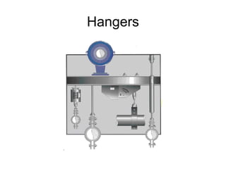
#105 Pipe Hangers
These refer to the suspension components, including the following:
Drop Rod This is the principal suspension member of a hanger consistent of a rod threaded at both ends or having a thread at one end and an eye at the other. For identification. The latter may be termed an eyebolt drop rod.
Link Which is the connecting member between two pipe clips suspended one from the other and may be in the form of a rod having threads or eyes at both ends.
Clip This is attached to the pipe. Two types are included. a) Fabricated two‑ piece flat iron clip fixed to pipe with clamping bolts. b) Two‑piece casting in malleable iron, brass, etc. variously described as ring clip, split ring, etc., but best identified with its original designer as the Munzing ring.
Double pipe clip (e.g., double Munzing) refers to the upper clip of a two‑piece, or double‑hung assembly.
Spring As sometimes inserted with retaining plates or similar containers between the top adjustment nut and spherical washer.
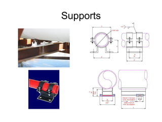
#106 Pipe Supports
These refer to assemblies for supporting the pipe from underneath and include:
Bearer Referring to the member which supports the Pipe. Bearers may be angle or channel section, etc. or tubular. In the simplest form of pipe support, the pipe rests direct on bearers.
Roller Mounted in a suitable chair or carriage and inserted between pipe and bearer to reduce noise from pipe movement.
Shoe Is an extension piece attached to the pipe to accommodate pipe movement without displacing lagging. Shoes may be flat – bottomed where mounted direct on bearers or shaped for use in conjunction with rollers.
Guide Maybe associated with any support assembly for the purpose of locating the pipe. Guides may be rigid hoops of frames allowing clearance for pipe movement or fitted with rollers to reduce friction.
Anchor referring to a rigid clamp or stop to prevent pipe movement resulting from expansion.
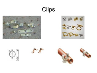
#107 Clips
This is attached to the pipe. Three types are included:-
1. Proprietary brass or steel or copper screwed directly to walls
2. Fabricated two‑ piece flat iron fixed to pipe with clamping bolts,
3. Two‑piece cast in malleable iron, brass, etc. variously described as ring clip, split ring, etc., but best identified with its original designer as the Munzing ring. Double pipe clip (e.g., double Munzing) refers to the upper clip of a two‑piece, or double‑hung assembly.
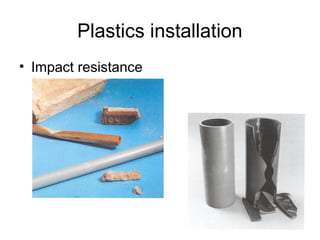
#108 Impact resistance
The flexible / ductile nature of a number of thermoplastics (ABS in particular) means that impact with the pipework results in the distortion rather than the failure of the material as would be experienced traditionally with a soft copper installation
In contrast the fracture of brittle materials where plastcisers have not been used or the material is used below its minimum temperature range is accompanied by rapid crack propagation and material failure / fragmentation.
However thermoplastics do not have the same mechanical strength as traditional ferrous materials meaning in restricted plant areas or risers shafts where the pipework installation is although incorrectly but frequently used as access equipment the installation is less resistance to damage.
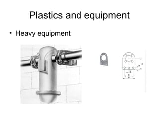
#109 Heavy equipment
Large valves, strainers and other heavy equipment require to be independently supported to prevent undue loading onto the pipework installation.
Although any pipework installation should be adequately supported to prevent the system load being from transferred to the plant and equipment that forms part of the system, traditional materials can adequately support the weight of the system valves and ancillaries without the need for these to be independently supported.
#110 Maximum Intervals Between Pipe Fixings
The space of pipe fixings is governed mainly by two considerations:-
That the stress due to bending of the pipes should not exceed a sensible value,
That the deflection should not be so great as to be objectionable in appearance or prevent the pipe from being drained.
Stress due to bending of the pipeline under its own weight and the weight of its contents cannot be considered in isolation in all cases; it is bound up with such questions as the amount and direction of other stresses resulting from internal pressure and from expansion of the pipes. Stresses in pipelines arise mainly from three causes:-
Stress due to the internal pressure of the fluid in the pipes. Stress due to internal pressure is commonly not very great.
Stress due to bending under the pipe’s own dead weight. A bending stress due to the weight of the pipe may in some conditions be in the opposite direction to the bending stress due to expansion and may relieve some of the latter stress. In a single span the maximum stress occurs at the bottom of the pipe midway between the two supports; in a multiple span it occurs at the top of the pipe and immediately over a support. In the former case the stress is 50% larger than in the latter.
Stress due to movement of the pipe occasioned by its expansion when the temperature is raised. Stresses due to expansion can vary widely but can be very small if suitable bellows expansion joints are used and if the operating temperatures are not very high, but even at the highest temperatures it is not difficult with proper provision for expansion to limit the expansion stresses
Two considerations govern the permissible deflection:-
the appearance of the pipeline which must not look as if it is hanging in festoon,
the question of drainage, that is the avoidance of pocketing in the pipeline leaving water in the deflected lengths between supports.
Tables of pipe supports in general are shorter than those necessary as they appear to be based on a constant bending stress due to support spacing which is only 10% of the total permissible stress. This is unrealistically and unnecessarily restrictive, quite apart from the fact that a constant stress is in our view an inadmissible design criterion.
#111 Supports / bracketry
Thermoplastic systems will require supports to be places at closer centres than traditional ferrous materials. As with traditional ferrous pipework materials the support centres will depend on the material and diameter of the pipework, however the plasticity of the materials at temperatures above ambient require that the support centres are reduced as the temperature of the carried fluid increase.
Due to thermal expansion to ensure that the pipework installation does not “snake” supports that provide lateral restraint but unrestricted axial movement should be utilised. This means that commonly encountered support systems of drop rods and pipe clips may need to be discarded in favour of either proprietary pipe clips or saddle guides.
#112 Remember the benefits for the installer are not always benefits for the designer / specifier.
Light Weight = Easy to handle / distribute
Material handling easier particularly with larger pipe sizes where mechanical assistance is frequently required to allow for the erection of steel pipework
Can be installed by a semi skilled labour force
Limited skills are required to prepare and produce an affect joint over the skills that are required for example to produce a screwed joint. However a skilled operative produces a higher quality installation as they have an understanding of layout, commissioning requirements, access for maintenance etc.
Reduced installation time
Overall cost saving
A reduction in the cost differential between the materials (thermoplastics have consistently been more expensive than traditional ferrous materials) has indicated that overall cost savings primarily through the reduced installation time and subsequently labour costs are possible.
#113 Trenches are invariably carcased early in the building programme, often before our requirements are finalised. Therefore, when agreeing trench size or making provision for fixings, aim at maximum flexibility. Almost inevitably, additional services will have to be accommodated at a late date. Allow adequate space below and between pipes for jointing ‘in situ’, particularly with welded lines. In most trenches, due to changes in level and direction etc. the scope for lowering prejointed pipe lengths into position is limited, with adverse effect on the number of positional joints required.
Trench construction invariably incorporates some form of waterproofing, usually an additive to the carcase mix. Occasionally, it may consist of a membrane between the carcase and an inner protective lining of bricks or blocks. Under these conditions, it is usually permissible to penetrate the completed structure for small fastenings, bolt inserts etc. but built-in attachments involving random cutting away are prohibited.
To overcome these structural problems in shallow trenches builders work slots should be formed in the trench walls to house the cross bearers. For deeper trenches in which, say, the majority of pipes are cantilevered slotted channel inserts are more convenient. This should not be construed as a recommendation for us to purchase the inserts; it is an example of their use in over coming a structural problem. As such, if the inserts are not already specified, they should be recommended to the Client for the builder to supply.
From the above it is obvious that fixing requirements in trenches must be given the necessary priority in our own design programme. If for any reason slots or channel inserts cannot be cast in the structure alternative fixing arrangements at a later stage must be subject to local agreement. Note, however, that the alternatives will invariably result in increased costs and leave less space available for pipe runs.
Trench floors should be graded to a sump; pipes, wherever possible, should be laid to fall in the same direction as the trench for drainage. Steam and condense may have to be graded to independent falls.
The use of hangers should be avoided for the following main reason:
Attachments or bearers spanning the top of a trench restrict access during erection. For example, they limit the lengths of pipe that can be jointed before fixing, whereas supports are of assistance throughout erection.
Trench depth is normally insufficient to accommodate the necessary minimum drop rod lengths.
#114 These are horizontal tunnels and crawl ways in which access for erection and maintenance is from the terminal points and temporary intermediate openings are provided.
Other services Ducts of this nature are invariably trunk routes for other services, as well as our own. Therefore, all examples assume some degree of co-ordination with other sub-contactors. Obviously, conditions may be less or more favourable in practice.
Access Temporary openings may be essential for installation. They should be located between or to the side of pipe runs.
Restricted space In many instances this is the direct result of our having failed to visualise, or failed to impress the Client that the tunnel or crawl way must be sized around the most congested situation, usually at junctions or at intersection with other services. Having accommodated these, the spacing of the long intermediate runs may appear extravagant and this may be inevitable; a properly sized tunnel nearly always appears oversized on completion. The main problem is to persuade the Client whose interests, initially, will be in excavation and construction costs. This aspect of the work is of such importance that no specific recommendations are made for dealing with ‘traffic jams’. Whatever the cause, weather due to oversight on our part or pressure from the Client, the resulting improvisations will be uneconomical
Structure Most tunnels and crawl ways are below ground level. Thus, water-proofing is a common feature of construction. In most cases, this will be in the form of an additive to the carcase concrete mix. Occasionally, it may consist of a membrane sandwiched between the outer carcase and an inner skin of bricks or blocks on the walls and a protective screed on the floor. When considering th fixings in detail, proposals for cutting away or fastening will be dictated by the method of proofing or by such ruling as maybe laid down concerning penetration of the completed carcase. Everything depends on conditions locally; for example, the water-table of the surrounding area. The problem is so often associated with work below ground level that the matter should always be queried before preparing working details.
Erection procedure As far as possible, fixings should allow unobstructed access for offering single or pre-jointed pipe lengths into position from the front, i.e. the agreed walking or crawling gangway. In other words, pipes should be shelved, not threaded.
Fixings general To facilitate ‘shelving’, pipes should be cantilevered suspended or mounted in wall-fixings.
Larger pipes As far as possible, these should be at low level, with weight carried to the floor and ‘steadied’ from the wall.
#115 To conceal it
To reduce heat losses
For spatial reasons – For pipe that has to stretch hundreds of metres if not kilometres ……..
For economic reasons – underground pipe does not require protective concrete ducts
Installation
Can avoid use of expansion joints
Working around congestion
Maintenance
Points on valve turning, leak detection etc
#118 “Sets”
Flexibility can be built into a pipe system by existing bends and loops and additional bends and loops to absorb expansion
Cold draw
If expanding pipes are stretched axially to 50% of the expansion then only 50% of the total expansion needs to be accommodated in the “Sets”.
#119 Thermal Expansion
The coefficient of expansion for thermoplastics dependant on material selection is between 5 and 12 time greater than conventional mild steel pipework.
Unless controlled through anchors and guides to restrain the pipework and direct thermal expansion within the system to points that allow the affects of thermal expansion to be relieved in a controlled manner at either changes in direction or through expansion loops the greater coefficient of expansion and subsequently the greater increase in pipe length for any given change in temperature over conventional materials requires that thermal expansion is given extra careful consideration.
for Mild Steel 11.3 m/m x 10-6/°C (See CIBSE Guide B 1988, Table B16.2)
for PE pipe 140.2 m/m x 10-6/°C (See CIBSE Guide B 1988, Table B16.2)
#120 Anchors
Are pipe fixings that can resist all the forces due to pipe work expansion
One pulled bend
#121 Guides
Allow axial expansion but not lateral expansion in order to eliminate buckling of the pipe
Two pulled bends
Guides for two pulled bends
It is not possible to use guides as the reduction in effective length is cancelled by the loss of flexibility.
#122 Expansion loops
If the loop is not centrally placed the stresses are higher than if they were centrally placed.
The most economical loop with the least anchor loads is when the distance to the loop from the guides is equal and the axial part of the loop is half the distance between the guides.
Guides for expansion loops
Guides may be required to prevent buckling. They should be located equidistant from the loop.
#123 Branch off expanding pipe
The branch needs to be unrestrained for long enough not to over stress the branch due to expansion in the main pipe.
Branch may be welded or screwed
Branch may be horizontal or vertical
Branch can be assumed to be guided or anchored if the main can move laterally.
#127 The Thermal expansion in this short guide only deals with expansion in the axial direction. It doesn’t deal with the 3-D interaction and effects of the pipe expansion.
For complex systems and to understand the 3-D aspect of pipe stress analysis, expansion, seismic effects, building expansion, vibration and water hammer, computer modelling can be used. Programs such as AutoPIPE and CESAR are available for this.
AutoPIPE is a Windows based pipe stress analysis program that has been used by Arup on projects such as:
HSBC Tower at Canary Wharf
Biogen – Pharmaceutical Plant in Denmark
Pfizer – Building 530 in Sandwich, Kent
Shell Boiler Plant – Waterloo, London
For further details on AutoPIPE, contact Davar Abi-Zadeh or Michael Lorimer in Industrial Consultancy Group (ICG)
#128 Types
Open tank feed and expansion.
Pressurization using diaphragm tank.
Pump pressurization.
#129 Pressure = Force per unit area
In simple terms the pressure at a point is the sum of
gravitational head (remember P=pgh)
10m head = 1000x9.8x10 = 98,000 Pa = 100 kPa = 1 bar
velocity head (1/2pv2) – we can usually ignore this
2m/s head = 0.5x1000x2x2 = 2,000 Pa = 2 kPa = 0.02 bar
pump head, less frictional losses due to pipe & fittings
Beware - the instantaneous pressure can be much higher than this especially with electronic valves closing very quickly (leading to “water hammer” shock waves)
#130 An open feed and expansion tank feeds water into the system that escapes from the system due to leaks or draining down the system.
The size of the tank should be based on the expansion volume of the water in the system.
It is traditional to have an open vent in the system as protection against explosion in addition to the safety valve. The open feed and expansion tank cannot be used for systems that operate above normal atmospheric boiler temperature
Locations of feed and expansion tank
It needs be located above the highest point of the system so that the pipework system is under positive pressure, that air is not drawn into the pipe work, if there is open vent, that the heating water does not continuously flow up the open vent and down the feed and that there is sufficient positive suction head on the inlet to the pump.
Feed & vent should be on suction side of pumps
Negative pressure & cavitation if feed on flow side of pumps
Air locks, especially if level of feed & expansion tank is not much higher than highest pipework
Risk of roof pipework around tank freezing especially if above insulation layer
#131 If the pressure becomes too high the spring lifts and allows water/steam out
Final safety feature – in a typical LTHW system it should never operate. In a malfunction the BMS should shut down the system on high pressure alarm before the valve operates
#132 As the water is heated it expands, the pressure rises, and eventually one component will reach its maximum safe working pressure (the weakest link)
You must calculate the system pressure corresponding to this (the “maximum working pressure”)
Although slide is a joke, the result of miscalculating the high pressure limit are potentially extremely serious, and is one of relatively few ways in which building services engineers can be directly responsible for explosions, building collapse and deaths.
#133 Several ways of achieving this (see later) but most common is pressurisation unit
Has more bits to go wrong
Needs to be the right size
Plant cutting out due to high / low pressures
Wrongly sized pressure vessel
Wrong location for pressurisation vessel
Loss of air from pressure vessel (see later)
#134 Pressurization units are used on larger systems and combine automatic feed water with pressurization. They are always used with systems that operate above normal atmospheric pressure. Some of them achieve feed water and pressurization through the use of a constantly running pumps and controls whilst other use diaphragm vessels and intermittently running pumps and pressure relief valves called spill valves.
Pressurization units
Can be located anywhere but are normally located in plant room close to the thermal plant for ease of operation. They have the advantage that they do not need to be located above the highest point of the system.
Consists of water tank with float valve
Pump pumps water from the tank into the system when the pressure is too low.
Typically sends high and low pressure alarms to the BMS or local controls to shut down the boiler/chillers
Bypass the unit with a flexible connection (normally disconnected) to allow you to fill up the system quickly – see later diagram on location of unit
Depending on the contamination separation required by the water supply company, a water tank air gap or a Reduced Pressure Zone (RPZ) valve may be required to avoid back contamination of the potable water main. A double check valve may not be acceptable.
#135 Circuits with low loss header connecting primary and secondary – null point must be at the centre point of the header (although anywhere on the header is probably OK).
Other types of circuit – location less critical but usually located on return side of pump, to make sure that all parts of system are at positive pressure.
Gravity loop is used on heating circuit to try and reduce the likelihood of hot water convection currents heating up the pressurisation vessel rubber bladder and reducing its life
Valve to expansion vessel should be locked open – if accidentally closed then pressure would rise
#136 When a diaphragm expansion tank is used the system is filled by a mains pressure water connection or temporary pumped water. The system will be protected against explosion by a safety valve. The diaphragm expansion tank must be sized on the expansion of the system and the ability of the diaphragm vessel to accept expansion. Diaphragm expansion tanks can be used for systems that operate above normal atmospheric pressure but the feed water needs to be supplied automatically into the pressurized system, so that there is no normal possibility of loss of pressure.
Location of diaphragm tank
When a diaphragm expansion tank is use the pressures are higher than would occur if a feed and expansion tank were used. The diaphragm expansion tank can be located anywhere in the system but is normally located in a plant room close to the thermal plant for easy of operational. The location also affects the ability of the diaphragm to absorb expansion
Must fill with compressed air to required pressure to just be adequate to support the water to the top of the system before filling the system with water. This is the cold fill pressure.
Acceptance Factor of the diaphragm = 1 – (1+Pac)/(1+Pmax) Pac = air cushion pressure (in bar)
maximum of 50%. Depends on manufacturer and relates to ability of bladder to stretch and absorb changes in pressure.
Common problems:
loss of air pressure – can be caused by someone accidentally releasing the vent valve, or by gradual leaks – will cause high pressures in system. Solution – re-pressurise air cushion
#137 Pressure hierarchy
The highest cold pressure is at the bottom of the system due to the static pressure.
The cold fill pressure is the pressure pumped into the diaphragm to support the water to the top of the system.
The final pressure is the pressure after expansion when the system is up to temperature
The safety valve is selected for the pressure to protect equipment and needs to be above the final pressure
The lowest rated item need to withstand the final pressure including the static head of the system.
#138 Basement Plant Room
Boiler is likely to be the “weakest” link
#139 Roof top plant
Boiler may still be component with lowest working pressure, but may instead be radiators/fan coils etc in basement
#140 (CHECK YOUR MANUFACTURER AND DATA-SHEETS)
Boiler : typical 3 - 5 bar
Radiator : typical 4 - 8 bar
AHU coil : typical 10 - 16 bar
Flexible connections (s/s braid): typical 10 bar
Fan coil unit coil : typical 12 - 15 bar
Plastic valves : 5 - 16 bar
Brass 4 port control valves : 16 bar
Steel pipework : 16 bar
N.B Test pressures are usually 1.5 times maximum working pressure
#141 Input information
Location Basement
Maximum water temperature 80 C
Initial fill temperature 4 C
System water content 5000 litres
Static head at the bottom of the system when the system is full 17.5 m WG
Fill pressure margin 0.3 bar
Percentage expansion 2.91%
Normal maximum acceptance factor 0.4
Component (radiator) lowest working pressure 4 bar
Static head of vessel below radiator 3.5 m WG dPh’
Pump head at component with lowest working pressure 0.1 bar
Safety valve margin 0.3 bar
#142 In tender documents we should aim to specify:
fill pressure
max working pressure
safety valve setting
and preferably also the low & high pressure alarm set points
Do you give the size of the pressurisation vessel?
#144 Cleaning flushing and venting of water filled pipework systems is required before commissioning commences.
It is important.
Pipework systems are vulnerable to blockages of small valve apertures with debris which is created by:
Surplus jointing material and building debris getting into the pipe system while being constructed
Mill scale and corrosion debris formed and released when sections of the pipework are pressure tested, drained and left empty
#145 Cleaning
Pipework systems are vulnerable to blockages of small valve apertures with debris which is created by:
Surplus jointing material and building debris getting into the pipe system while being constructed
Mill scale and corrosion debris formed and released when sections of the pipework are pressure tested, drained and left empty
To reduce these problems a rigorous cleaning and flushing routine is required
#146 Chemical
Some water treatment specialist contractors undertake an acid clean. This removes iron oxides that have occurred due to pressure testing and leaving the pipes with some water in them and a lot of air. Once acid cleaned it leaves the pipes vulnerable to rapid corrosion. For this reason acid leaning should be left to the specialist water treatment contractors.
A dispersant clean ensures sludge and nearly loose corrosion bits are released and kept in suspension to be flushed out. The dispersant leaves a layer on the surface to assist in reducing further corrosion. However, this layer is subject to erosion and should be left to the specialist water treatment contractors.
#147 Flushing
Rigorous flushing is necessary to completely remove all solids. After cleaning and flushing the steel surfaces should immediately be inhibited to reduce corrosion.
Flushing at high velocity without putting dirty water and bits through terminals and small orifices requires a number of special design features.
Isolating valves and valved bypasses of all terminal units
Strainers possibly with flushing baskets preceding plant.
Main size dirt pockets with removable ends
Large drain cocks and isolating valves at the bottom of risers.
Valved connections on on primary and secondary circuits to connect temporary flushing tanks and pumps
Valved bypasses at the end of each circuit.
Drain cocks on terminal flow connections for back flushing and proving blockage free
Valved cross over connections on pumps to enable the flow direction to be reversed
#148 Venting or Air removal
Air removal needs special techniques and should be designed into the pipework system.
Failure to remove air results in corrosion, noise, pump de-rating, loss of heat exchange and inaccurate flow measurement.
Air bottles at high points allow the system to be filled but do not capture the small bubbles in circulation. These bubbles are swept past air bottles and can only be removed by reducing the water velocity to below 0.2 m/s.
The moste effective way to achieve this in an open tank feed and expasnion system is to have a temporary connection of the flow run into the feed tank and wich is run until no bubbles are seem discharging into the tank.
For pressurized systems the process is:
Fill the system from the bottom releasing air at the high points.
Valve of the pressurization unit
Fit a temporary tank at the top of the system with a feed into the return and a discharge from the flow back into the tank.
Achieve a flow rate of 10% whilst ensuring there are no negative pressures in the system.
Leave circulating until there are no more bubbles.
Remove the temporary equipment and open the connectiosn to the pressurization unit.
#149 Getting systems clean is important as commissioning dirty systems will be abortive.
Use a water treatment specialist to provide a flushing, cleaning and corrosion inhibiting service.
#151 Setting a system to work.
Bringing a system from a state of static completion into dynamic operation.
Checking the performance of plant and the complete system against the specified performance.
#152 In all constant flow circuits the correct water flow needs to be achieved in each branch to ensure that each terminal has its design flow within reasonable limits. This as achieved by regulating valves in the returns to each terminal and in the returns to each branch circuit. The flow is measured by a flow measuring device which is used as a manual balance is undertaken in accordance with the applicable commissioning codes tolerance.
Proportional balancing
Measure all the flows with the regulating valves open
Calculate the % of design flow for all terminals
If the % design flow of an intermediate terminal is the lowest, adjust the regulation valve for the terminal at the end of the branch until it has the same % design flow as the intermediate terminal
Start with the leg that has the highest & design flow
Working back from the last terminal or branch, adjust each regulation valve in turn until the % design flow is the same as the current design flow in the last terminal. The current % design flow in the last terminal will change as the balance is achieved and needs to be used as the reference terminal.
#153 If the plant terminal equipment and pipe routes are the same as those used for pipe sizing then a balance may be achieved by setting the regulation valves to their calculated settings. This is rarely the case as equipment frequently changes during the design and installation. Where the terminal units have a high resistance changes in pipe routes has little effect and the systems tend towards self balancing.
#154 Variable flow systems
Need to include control devices that balance the varying flow requirements. If they are commissioned and functioning correctly the terminal flows will be achieved without balancing.
The control of pump speed should give adequate and not excessive pressure drop across index terminal and the nearest terminal to the pump at both maximum and minimum loads. These loads can be simulated by opening all of the two port valves and measuring the pump flow and hence design diversity
Variable flow systems should be low energy systems. However, the pressure drop requirements to achieve control authority and the high heads that are required at minimum flow rates can reduce the energy savings expected.
#155 Pressure diagram
It is sometimes useful to plot the dynamic changes only starting at the cold feed and working around the system in the direction of flow.
#156 Flow measurement
Pipework systems that have pumped circulation need to be balanced to achieve the correct flow in each section of the circuit and in the terminal units.
Measurement of fluid flow can be achieved in a number of ways but the traditional method is to measure the pressure drop caused by the fluid flowing through an orifice plate or a valve with a known characteristic.
The pressure drop is normally measured using a water box manometer.
If the range of the manometer is exceeded by the pressure drop it is extremely easy to deposit the mercury into the pipework system, so be very careful if you use one. They invariably include a bypass that should be left open at all times other than when a reading is being taken. When a reading is being taken the bypass should be closed slowly to check that the pressure drop is not outside of the instrument range. If the differential pressure approaches the limit of instrument measurement you should stop closing the bypass and start opening it again.
#157 Temperature
Tempcon air and water recording thermometer. Although temperatures are the ultimate requirement for comfort commissioning of pipe work systems is largely about measuring pressure differentials. Where temperatures need to be measured the measuring probe is best inserted into the water and not by measuring the pipe surface temperature. The probe can be inserted through a self sealing plug in the wall of the pipe.
#158 In a contract where Arup undertake the detailed design, commissioning is far to important to be left to the contractor. Make sure there is a commissioning supervisor.
Don’t lose the time that is required to complete the commissioning by being squeezed between delays in construction and need of the client to obtain completion.
#159 CIBSE Water Distribution Systems - Code W : 2003
BSRIA Commissioning of Water Systems in Buildings : AG 2/89
Commissioning Specialists Association:
a. White Water Balancing : GN/1
b. Automatic Balancing Devices : GN/2
c. Variable Volume Water Systems : GN/3
#160 Guidance on the provision of space for access to plant and the space requirements for effective and safe maintenance of building services.
#161 Legislation
This is a health and safety issue and access needs to comply with the regulations of the country in which the project is to be built.
#162 Plantroom design
The basic considerations are
Task, type difficulty, frequency, and duration
Hazards. hot or cold, sharp, atmosphere, projections, moving parts, live electric parts, flammability, toxic, noise, heavy, falling, tripping
Staff, type ,supervision, size of team.
Maintenance
Routes to equipment
Standing room
Access ladders
Access gear
Cranage
Step overs
Access frequency
Less than a month – Permanent and clear
Up to 6 months – readily removable hatches
Greater than 6 months – demountable partitions and doors.
Location of plant
Removal & replacement
Escape routes not blocked by maintenance
Functional requirements
Practical
Adjacent access space can be shared
#163 Distribution routes
Branches from vertical risers will be congested.
Co-ordinate all services.
Number of risers needed for all services
#164 Boilers
Need access on all four sides
Oil storage
Tube withdrawal
#165 Chillers
Air cooled are dominated by air flow requirements
Water cooled Tube withdrawal and heavy machinery lifting gear.
#166 Pumps
Frequent inspections for leakage
In line pumps given frequent access
#167 Pressurization units
Frequent controls inspection
Pressurized gas
Water storage
Space for assembly of sectional tanks
Inspection for sectional leaks if against a wall
Air Handling units
Removing panels
Coil withdrawal
Drains and traps and legionella
Filter replacement
Axial fans
Frequent access mounted at high level
Even worse is through false ceilings
Cooling Towers
Cleaning of the pack
Legionella in discharge
#168 Watch it notes
Do not let the architect or client push you into agreeing to plant installation and access that is so constrained that it is unhealthy or unsafe.
Although this issue is passed onto the contractor, the building, distribution and plantroom spaces have to be big enough for the contractor to comply with the law.
#169 Defence Works Functional Standard Design & Maintenance Guide 08 – Space requirements for plant access, operation and maintenance 1996 – ISBN 0117727857
Arup application guide
UK Health and safety at work act 1974
BSRIA Space and weight allowances for building services plant – inception stage design 1994