Downloaded 169 times
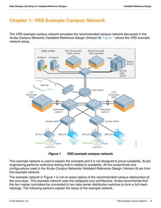
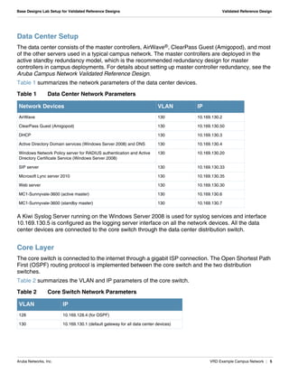
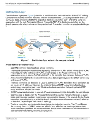
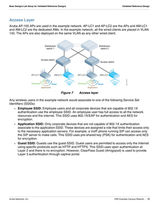
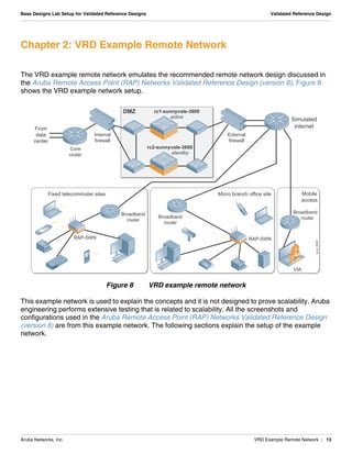
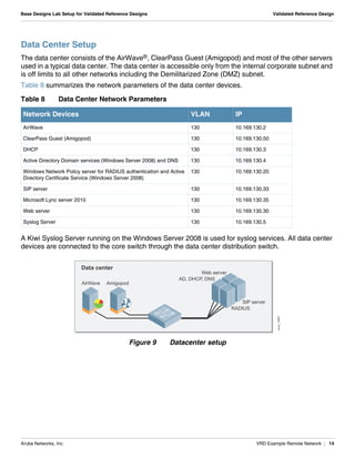
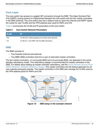
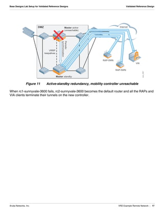
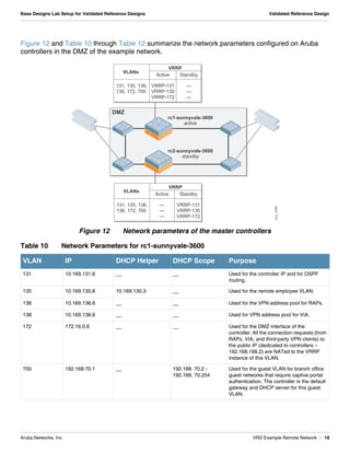
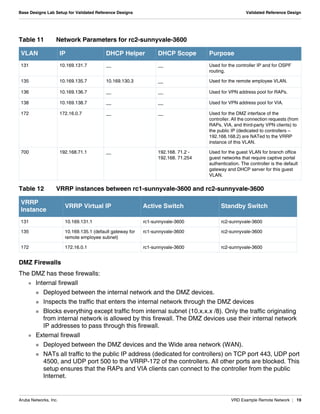

The document summarizes the setup of an example campus network used to demonstrate an Aruba validated reference design. Key elements include: - A data center with controllers, AirWave, servers and core switch. - A distribution layer with two distribution switches connected to two Aruba controllers, with VLANs, VRRP and link aggregation configured. - The controllers are deployed in an active-active redundant model with VLAN pooling across controllers to support failover. - Network parameters like VLANs, IPs, DHCP scopes are defined for the controllers and distribution switches.


