The document provides instructions for using an On Board Diagnostic (OBD) tool to test the functions of a vehicle's multi-function steering wheel and diagnose any issues. It describes connecting the tool, navigating the tool's menu to select diagnostic tests, performing tests of steering wheel controls and reading trouble codes, and erasing fault memories after repairs. Safety notes are also provided to caution operating the tool from the rear seat during a road test.
AUDI A4 B5 1.8L 1996 ELECTRICAL EQUIPMENT 01 79 instrument cluster, on board ...Gherghescu Gabriel
The instrument cluster in Audi vehicles evaluates various vehicle service requirements based on input data. It can also process flexible data to reproduce standard functions when limits are set correctly. The cluster has extensive OBD capabilities to diagnose faults in other vehicle systems. When issues occur, diagnostic trouble codes are stored and can be retrieved using a scan tool to help locate the problem.
The ultrasonic interior monitoring system uses ultrasonic sensors to detect unauthorized entry into a vehicle. It consists of ultrasonic sensors in the pillars that monitor side windows, a switch for the system, and sensors for rear windows. When the monitoring signal deviates from normal, the control module activates the anti-theft alarm. It can store diagnostic trouble codes for issues like short circuits or incorrect signals from sensors.
Way To Use Autel Maxiscan JP701 Scanner | VtoolShopAmy joe
JP701 supports all 9 tst modes of the latest J-1979 OBD2 test specs and used for Reads Engine, Transmission, ABS & Airbag Systems for major Japanese vehicles.
The programming manual provides instructions for setting up and programming the Altivar 71 variable speed drive. It includes descriptions of the graphic display terminal, navigating menus and parameters, factory configuration settings, application functions, and safety recommendations for setup. Programming involves configuring menus such as [SIMPLY START], [MOTOR CONTROL], [INPUTS/OUTPUTS], [COMMAND], and [APPLICATION FUNCT.] to customize the drive for the user's application.
Autel MaxiScan MS509 OBD II/EOBD Scanner supports all nine OBD II test modes on all OBD II compliant vehicles to enable technicians to accurately diagnose complex problems.
This is the user manual of FasDiag OM123.
>> READ MORE: https://www.obdadvisor.com/best-obd2-scanner-review/
Here is a detailed review of the best OBD2 scanners based on my own experience, including:
- Compatibility
- Features and Functions
- Pros and Cons
Check it out to get the REVIEW and some NOTES about using the scanner.
Autodiagnosticobd.com users manual of mb880 code reader星田 龚
Our website www.autodiagnosticobd.com you can find out lots of useful diagnostic software and keygen xentry free download link, more details you can contact us:
Skype: obd2tuning.com
Email: adktechjulie@outlook.com
MSN: adktechjulie@hotmail.com
website: www.autodiagnosticobd.com
1) The document provides safety precautions and instructions for using a diagnostic tool to diagnose vehicle systems. It describes connecting the tool to the vehicle, selecting diagnostic functions like reading fault codes, erasing codes, and reading live data.
2) The tool can diagnose vehicle control systems for engine, transmission, ABS brakes and more. Instructions are provided for selecting the vehicle system and using various tool functions to diagnose issues.
3) Settings and programming functions are also described, like accessing vehicle adaptations, coding, and security settings with the correct login credentials.
This document provides an overview of an automotive diagnostic scan tool. It describes the tool's features, specifications, included accessories, navigation buttons, and how to perform basic operations like turning the tool on/off, connecting to a vehicle, looking up diagnostic trouble codes, and reviewing live vehicle data. The document also provides context on automotive diagnostics standards like OBD-II and common terminology used with scan tools.
How to use eu702 code reader - eu702 code reader use manual | VtoolShopAmy joe
eu702 code reader manual,The SC23 MaxiScan EU702 Code Sanner Read supports all nine OBDII test modes on all OBDII compliant vehicles to enable technicians
Innova 3020D Owner’s Manual
>> READ MORE: https://www.obdadvisor.com/innova-3020d-review/
Here is a detailed review of the Innova 3020D scan tool:
- Retrieve Diagnostic Trouble Codes
- Read Diagnostic Trouble Codes
- Erase Diagnostic Trouble Codes
- Compatibility
Check it out to get the REVIEW and some NOTES about using this scanner based on my own experience.
Autel max scan-gs500-scan-tool-user-manualQuliar Lucy
This document provides instructions on using an OBD2 diagnostic scan tool. It begins with safety warnings and an overview of On-Board Diagnostics II systems and diagnostic trouble codes. It then describes the key features and operation of the scan tool, including navigating menus, viewing vehicle codes and data, erasing codes, and testing components. The scan tool can be used to retrieve diagnostic trouble codes, check readiness monitors, view live vehicle data, and perform tests to help diagnose emission and drivability issues.
This document provides information about On-Board Diagnostics (OBD) II systems and how to use an automotive scan tool. It discusses OBD II components like Diagnostic Trouble Codes, monitors, and modes of operation. It also describes the scan tool, specifying how it connects to the vehicle and what the LED indicators mean. Safety precautions are outlined for using scan tools and performing vehicle diagnostics.
The document provides information about OBDII systems and instructions for using the Creader V+ diagnostic tool. It includes sections on general OBDII information, product descriptions, tool setup instructions, and operations like reading codes, erasing codes, and special tests. Key details covered are OBDII standards, diagnostic trouble codes, monitor readiness, tool interfaces, connection process, and navigating code reading and other diagnostic functions.
Autel AutoLink AL519 OBDII EOBD & CAN Scan Tool is truly the ultimate in power and affordability, allowing users to do their jobs faster. AutoLink AL519 Support all 10 modes of OBDII test for a complete diagnosis. In addition, thousands of troubleshooter code tips help technicians to save diagnosis and repair time.
http://www.buyobdtool.com/wholesale/original-autel-autolink-al519-obdii-and-can-scanner-tool.html
Autel AutoLink AL519 Function:
1. Turns off Check Engine Light (MIL), clears codes and resets monitors
2. Features the unique patented One-Click Readiness Key for quick State Emissions readiness check and drive cycle verification
3. Retrieves generic (P0, P2, P3 and U0), manufacturer specific (P1, P3 and U1) codes and pending codes
4. Internet updateable and upgradeable
5. Prints data via PC
6. Retrieves vehicle information (VIN, CIN and CVN)
7.Troubleshooter code tips guide technicians to the root cause of a trouble code faster, saving diagnosis and repair time
This document provides instructions for setting up and using a Direct/Residual Shear Apparatus machine. The summary includes:
1) The machine arrives ready for use with calibrated instrumentation already installed and assigned to inputs. Users should verify the calibration and ensure instruments are plugged into the correct channels.
2) The initial setup involves configuring date/time, display brightness, and preference settings like units of measurement and automatically updating the system.
3) Detailed instructions are provided for sample preparation, consolidation, performing tests, and calibrating the instrumentation if needed.
This is the user manual of Autel MaxiScan MS300.
>> READ MORE: https://www.obdadvisor.com/autel-ms309-ms300-launch-creader-v/
Here is a detailed review of the scan tool based on my own experience, including:
- Compatibility
- Features and Functions
- Pros and Cons
Check it out to get the REVIEW and some NOTES about using the scanner.
This document provides instructions on how to use an automotive scan tool. It describes the scan tool components and specifications. It explains how to power the scan tool, connect it to a vehicle, and navigate the user interface. It also covers diagnostic trouble codes, onboard diagnostics systems, product setup instructions, and warranty information.
Ancel FX6000 Owner’s Manual
>> READ MORE: https://www.obdadvisor.com/ancel-fx6000-review/
Here is a detailed review of the Ancel FX6000 scan tool:
- Features and functions
- Advanced functions
- Compatibility
Check it out to get the REVIEW and some NOTES about using this scanner based on my own experience.
Antel AL301 User Manual
>> READ MORE: https://www.obdadvisor.com/autel-ml619-vs-ml629-vs-al629/
Here is a detailed review of the Antel scan tool based on my own experience, including:
- Features and Functions
- Vehicle Coverage
- Pros and Cons
Check it out to get the REVIEW and some NOTES about using this scanner.
Ancel FX4000 Owner’s Manual
>> READ MORE: https://www.obdadvisor.com/fx2000-vs-fx3000-vs-fx4000-which-best-suits-a-home-mechanic/
Here is a detailed review of the Ancel FX4000 scan tool:
- Design, Display, and Specifications
- System Diagnostic Functions
- Advanced Service Functions
- Supported Vehicles Makes
- Supported Protocols
- Warranty
Check it out to get the REVIEW and some NOTES about using this scanner based on my own experience.
This is the user manual of Veepeak OBDCheck VP39.
>> READ MORE: https://www.obdadvisor.com/best-veepeak-obd2-scanner-review/
Here is a detailed review of the Veepeak adapters based on my own experience, including:
- Compatibility
- Features and Functions
- Pros and Cons
Check it out to get the REVIEW and some NOTES about using the scanner.
This is the user manual of Topdon AL201.
>> READ MORE: https://www.obdadvisor.com/best-topdon-obd2-review/
Here is a detailed review of the Topdon scan tool based on my own experience.
Check it out to get the REVIEW and some NOTES about using this scanner.
Tachograph CD400 programmer User Manual obdii365OBD365
Tachograph programmer (Tacho) CD400 blue is designed for verification, calibration and configuration of control devices (tachograph) when installed on vehicles. The device allows you to define the W figure determination on measuring track or rolling road, K figure measure, can be used as speed simulator for the tachograph when checking the speedometer and odometer. http://www.obdii365.com/wholesale/tacho-programmer-cd400.html
Here are the steps to set the date and time on the FlashPAK:
1. Insert a job card with Supervisor Authority (see page 10).
2. Press Menu until you see the top level menu.
3. Scroll down and select System.
4. Scroll down and select Time.
5. Use the arrow buttons to change the date and time values.
6. Press Menu to save the settings.
The date and time will be used for timestamps in the Event Log. Let me know if you have any other questions!
AUDI A4 B5 1.8L 1996 ELECTRICAL EQUIPMENT 94 17 front fog lightsGherghescu Gabriel
The document provides instructions for removing and installing front fog lights on an Audi vehicle. It describes disconnecting the battery ground strap and removing components like the bumper, headlight insert, and housing cover to access the light socket. It explains how to release the bulb retaining spring, remove the old bulb, insert a new bulb, and reconnect connectors. Reinstallation follows the removal steps in reverse order, and it notes to adjust the front fog light level after installation by turning an adjusting screw under the bumper covers.
The document describes a PID control simulation program created to help understand PID controllers. It details the main window layout including the chart display panel, controller output panel, settings panel, and program modes panel. It then explains how to operate the simulator in both manual and programmed modes and provides an overview of PID controller concepts such as proportional, integral, and derivative control actions.
Forklift impacts, IM3 RFID operator card access controlTed Jurca
The document provides an installation and operational manual for a lift truck impact monitoring system with RFID card operator access control. It includes instructions for installing the system components, setting up the digital indicator and date/time, configuring operator access with RFID cards, and using the system to log impacts and complete mandatory safety checks before operation. Operators must scan a valid RFID card and the system will prompt them to verify the completion of safety check items. The manual also provides details on the RFID card reader specifications and programming additional cards.
This tutorial introduces a multi-tier ASP.NET MVC application that uses Windows Azure Storage services. It provides an overview of the email list management application, including its front-end interface, use of tables, queues and blobs for the back-end, and deployment to Windows Azure. The remaining tutorials will explain how to set up the development environment, build each component of the application, and deploy it to Windows Azure.
This document provides instructions for removing and installing front seats in Audi vehicles. It describes:
- Disconnecting the battery and connecting an airbag adapter before working on seats.
- Removing caps, screws, and other fasteners to pull the seat out of the vehicle.
- Disconnecting wiring connectors for heated seats or side airbags.
- Lubricating seat guide rails with grease after removal.
AUDI A4 B5 1.8L 1996 66 32 rear wheelhousing liner remove & installGherghescu Gabriel
The document provides instructions for removing and installing the rear wheelhousing liner on front wheel drive and Quattro vehicles. For front wheel drive vehicles, remove the rear wheel then remove 5 screws at the top and 4 at the bottom of the liner. For Quattro vehicles, removal and installation is the same as front wheel drive. Phillips-head screws should be tightened to 2.5 Nm.
AUDI A4 B5 1.8L 1996 ELECTRICAL EQUIPMENT 94 22 side-mounted turn signalsGherghescu Gabriel
Disconnect the battery before working on the electrical system to prevent damage. Remove side turn signal lenses by pressing them out of the fender opening and pull out the housing from the rubber socket. Individual bulbs can also be replaced by pulling them from the socket. Reinstall all components in reverse order.
AUDI A4 B5 1.8L 1996 ELECTRICAL EQUIPMENT 01 1 radio obdGherghescu Gabriel
The document provides instructions for using an onboard diagnostic (OBD) tool to test the radio system in Audi vehicles from 1998. It describes how to initiate the OBD program using the tool, select functions to check diagnostic trouble codes (DTCs), erase the DTC memory, and perform output tests. The document also includes a table listing possible DTCs, their meanings, and the corrective actions to address any issues found.
This document provides instructions for connecting a VAG1551 or VAG1552 scan tool to vehicles from 1996-1997 in order to perform onboard diagnostic testing. It describes locating and connecting to the data link connector, which is in the rear ash tray of 1996 vehicles and below the driver's knee bar for 1997 vehicles. It also provides troubleshooting tips for issues that may occur during rapid data transfer such as control modules not answering or errors in the communication link.
The document provides safety precautions and handling instructions for pyrotechnic seat belt tensioners. Only qualified personnel should perform installation, removal, testing and repair of seat belt tensioners. Undeployed tensioners must be rendered inoperable before disposal due to risk of injury. Proper protective equipment and procedures must be followed when deploying seat belt tensioners to avoid risks.
AUDI A4 B5 1.8L 1996 BADY 63 10 spoiler remove & installGherghescu Gabriel
This document provides instructions for removing and installing a spoiler on a vehicle. To remove the spoiler, first remove the bumper. Then remove the expanding clips on both sides of the spoiler by pulling out the pins and prying out the clips. Finally, unclip the retaining tabs from the spoiler and remove it from the bumper.
AUDI A4 B5 1.8L 1996 ELECTRICAL EQUIPMENT 91 1 radio systemGherghescu Gabriel
This document provides information about radio systems for Audi vehicles, including:
- Cautions for working on the electrical system and activating vehicle equipment after reconnecting the battery.
- An overview of the "Delta" and "Concert" radio systems, including component locations and multi-pin connector terminal assignments.
- Instructions for removing and installing various radio system components like speakers, amplifiers, antennas, and CD changers.
AUDI A4 B5 1.8L 1996 BADY 66 5 lower trim strip rear doorGherghescu Gabriel
This document provides instructions for removing and installing the lower trim strip on the rear door of a vehicle. To remove the trim strip, the three combination bolts are removed and the strip is slid out of the retaining clips toward the rear of the door. Installation is the reverse of removal. For an S4 model, the trim strip is removed by gradually pressing the tab on the retaining strip upward and pulling the trim strip out. Installation involves aligning and pressing the trim strip onto the retaining strip from the top to bottom and side.
AUDI A4 B5 1.8L 1996 ELECTRICAL EQUIPMENT 96 12 interior lights avantGherghescu Gabriel
This document provides instructions for servicing interior lights in an Audi Avant. It cautions technicians to disconnect the battery ground strap before working on the electrical system. The overview identifies the cargo area light, rear interior lights, bulb types and connectors. The instructions explain how to remove and install the rear reading lights and cargo area light by prying out the light, disconnecting the harness connector, removing the bulb if needed, and reinstalling by connecting the positioning hooks and engaging the catch.
AUDI A4 B5 1.8L 1996 BADY 55 12 rear lid vin 8 d xa 200 000Gherghescu Gabriel
The document provides instructions for removing, installing, and adjusting various components of the rear lid for a 1999 Audi vehicle with VIN 8D XA 200 000. It describes how to adjust the stop buffers and striker plate, remove and install the rear lid and lock, remove the locking cylinder, and adjust the panel gaps when reinstalling the rear lid. Precise tightening torques are specified for various nuts and bolts. Safety warnings are also provided when working with the gas-filled strut.
AUDI A4 B5 1.8L 1996 ELECTRICAL EQUIPMENT 27 48 cruise control systemGherghescu Gabriel
The document provides instructions for removing and installing cruise control systems on Audi vehicles. It describes the different components of cruise control systems for diesel, gasoline, and electronically-operated throttle vehicles. Instructions are given for removing and installing the control module, adjusting the actuator linkage, removing and installing the actuator and vacuum pump, and checking for leaks in the vacuum system.
AUDI A4 B5 1.8L 1996 66 31 wheelhousing liner remove & installGherghescu Gabriel
To remove the front wheelhousing liner, remove the front wheel and 10 bolts securing the liner below the fender. To install the liner, press the plastic tabs into holes in the fender and secure with 2.5 Nm Phillips-head screws. The document provides instructions for removing and installing the front wheelhousing liner on a vehicle, including identifying the relevant parts and specifying the removal of bolts and installation of plastic tabs and screws.
This document provides instructions for removing and installing a rocker panel cover on an Audi S4. The key steps are:
1. Remove the rear trim piece and front end piece.
2. Remove Phillips-head screws, twist locks, and cap nuts to detach the cover.
3. Press the wheelhousing liner aside and remove hex nuts and bolts to fully separate the cover.
4. Installation is the reverse process of reattaching with all hardware.
This document provides instructions for removing, installing, and assembling the rear bumper on an Audi Avant vehicle (VIN 8D XA 200 000). It describes the various components of the rear bumper, including brackets, bolts, and clips. The instructions note that before removing the bumper, other rear trim pieces must first be removed. When reinstalling the bumper, brackets are attached with bolts tightened to specified torques.
AUDI A4 B5 1.8L 1996 ELECTRICAL EQUIPMENT 96 1 center console switchesGherghescu Gabriel
This document provides instructions for removing and installing center console switches in an Audi vehicle. It cautions the user to disconnect the battery ground strap before working on the electrical system. The document describes how to remove switches by prying off the switch plate with a small screwdriver and then pulling the switch out with pliers before disconnecting the harness connector. Reinstallation involves connecting the harness, pressing the switch into place, and engaging the switch plate audibly. The emergency flasher relay location is also noted.
This document provides instructions for removing and installing door mirrors on vehicles. It describes removing the mirror housing from the door, removing the mirror adjustor by prying off the mirror glass and disconnecting harness connectors. It also details removing the door component carrier and replacing the entire mirror housing or just the power mirror adjuster. Special tools may be needed to remove the mirror glass and care should be taken to avoid paint damage.
AUDI A4 B5 1.8L 1996 ELECTRICAL EQUIPMENT 01 1 instrument cluster, on board d...Gherghescu Gabriel
The document discusses the Audi A4 instrument cluster, which comes in two versions - a basic version with a mini-check system or a high-line version with a multi-function LCD display. The instrument cluster is controlled by a microprocessor and can store diagnostic trouble codes. Using a scan tool, technicians can check the diagnostic trouble code memory, perform diagnostic tests, erase codes, code new control modules, and perform adaptations like setting the odometer after replacing the instrument cluster. The document provides details on initiating these scan tool functions and interpreting diagnostic trouble codes.
AUDI A4 B5 1.8L 1996 BADY ODB 01 69 central locking system obdGherghescu Gabriel
The document provides information about the central locking system onboard diagnostic (OBD) functions for Audi vehicles, including:
1. The central locking system has two pneumatic circuits that control different locking points and can be operated using the VAG1551 scan tool for diagnostics.
2. The scan tool can be used to check the control module version, diagnostic trouble codes (DTC) memory, initiate diagnostic test modes, code the control module, and read measuring value blocks to diagnose issues.
3. A DTC table lists potential codes that may appear when checking the DTC memory and provides troubleshooting steps to resolve common problems like short circuits.
AUDI A4 B5 1.8L 1996 BADY ODB 01 5 airbag w-o side air bag obdGherghescu Gabriel
The document describes an airbag system on board diagnostic procedure for Audi vehicles from 1997 to 1999. It outlines the various components of the airbag system for different year vehicles. The diagnostic procedure involves using a VAG1551 scan tool to check the control module, retrieve diagnostic trouble codes, run tests, and code the control module if needed. Safety cautions are provided regarding working with the airbag system.
AUDI A4 B5 1.8L 1996 ELECTRICAL EQUIPMENT1 203 cruise control on board diagno...Gherghescu Gabriel
This document provides instructions for testing the cruise control system on Audi vehicles with electronically-operated throttle valves. It describes how to use a diagnostic scan tool to view sensor values and switch statuses. Instructions are given for activating or deactivating cruise control using login codes. The document also describes how to use a breakout box to test wiring and components by checking for shorts or open circuits on specific connector terminals.
AUDI A4 B5 1.8L 1996 ELECTRICAL EQUIPMENT 90 25 instrument cluster location d...Gherghescu Gabriel
- The document provides instructions for removing and installing an instrument cluster on an Audi vehicle.
- If the letters "dEF" appear on the trip odometer display, the instrument cluster needs to be replaced.
- Checking involves disconnecting connectors and battery, removing screws, and installing in reverse order.
- Terminal assignments and connectors are identified for the instrument cluster.
- Steps are provided for checking engine speed and fuel level signals if those readings are faulty.
This is the user manual of FasDiag JD101.
>> READ MORE: https://www.obdadvisor.com/best-obd2-scanner-review/
Here is a detailed review of the best OBD2 scanners based on my own experience, including:
- Compatibility
- Features and Functions
- Pros and Cons
Check it out to get the REVIEW and some NOTES about using the scanner.
Veepeak OBDCheck VP30 User Manual
>> READ MORE: https://www.obdadvisor.com/best-veepeak-obd2-scanner-review/
Here is a detailed review of the Veepeak OBD2 adapters:
- Features and functions
- Compatibility
- Pros and cons
Check it out to get the REVIEW and some NOTES about using this scanner based on my own experience.
Autel max scan-gs200-scan-tool-user-manualQuliar Lucy
The document is a user manual for an auto code reader. It includes safety precautions for using the device and operating instructions. It also lists the product features and vehicle coverage. Finally, it provides definitions for diagnostic trouble codes that the code reader can retrieve from vehicles, including Volkswagen and Audi codes.
AUDI A4 B5 1.8L 1996 ELECTRICAL EQUIPMENT 90 1 instrument cluster location di...Gherghescu Gabriel
This document provides instructions for removing and installing the instrument cluster on Audi vehicles, including:
- Disconnecting the battery before working on the electrical system.
- Checking diagnostic trouble codes and recording odometer and service reminder readings before removal.
- Removing screws and connectors to pull the cluster out, then installing in reverse order.
- Checking cluster function after installation and initiating adaptations if needed.
It also details the locations of indicator lights and bulbs, terminal assignments for various connectors, and procedures for checking sensors connected to the instrument cluster.
How to use Abs Airbag Scanner Tool | VtoolShopAmy joe
This document provides information about using an airbag reset scanner tool, including:
1. Safety precautions must be followed when using the tool such as wearing protective equipment and parking the vehicle safely.
2. The tool can be used to check diagnostic trouble codes, monitor readiness status, and obtain other vehicle diagnostic data through the onboard diagnostic port.
3. Navigation and use of the tool involves turning it on, obtaining the login password, setting up the product, reviewing vehicle coverage, and performing diagnostics functions.
This document provides instructions for using the iCarsoft diagnostic tool or CR Plus. It outlines safety precautions, explains diagnostic functions like reading and clearing codes, and provides guidance on connecting the tool, navigating menus, updating software, and diagnosing vehicle systems.
This is the user manual of iCarsoft CR+.
>> READ MORE: https://www.obdadvisor.com/icarsoft-por-ii/
Here is a detailed review of the scan tool based on my own experience, including:
- Compatibility
- Hardware and Design
- Features and Functions
- Pros and Cons
Check it out to get the REVIEW and some NOTES about using this scanner.
This is the user manual of iCarsoft MBII.
>> READ MORE: https://www.obdadvisor.com/icarsoft-por-ii/
Here is a detailed review of the scan tool based on my own experience, including:
- Compatibility
- Hardware and Design
- Features and Functions
- Pros and Cons
Check it out to get the REVIEW and some NOTES about using this scanner.
Autel MaxiScan MS309 User’s Manual
>> READ MORE: https://www.obdadvisor.com/autel-scanners/
Here is a detailed review of the Autel scan tool based on my own experience.
Check it out to get the REVIEW and some NOTES about using this scanner.
This document provides instructions for troubleshooting engine issues on a 1997 Lexus ES300. It begins with connecting an OBD II scan tool or Lexus hand-held tester to the vehicle to check diagnostic trouble codes and freeze frame data. It describes inspecting the vehicle's diagnosis system in normal and check modes. It provides a fail-safe chart and instructions for checking for intermittent problems. It concludes with a basic inspection flow chart to methodically check the battery, engine cranking, air filter, idle speed, and ignition timing as potential root causes of engine issues.
This is the user manual of Xtool VAG401.
>> READ MORE: https://www.obdadvisor.com/xtool-vag401-review/
Here is a detailed review of the scan tool based on my own experience, including:
- Compatibility
- Display and Software
- Features and Functions
- Pros and Cons
Check it out to get the REVIEW and some NOTES about using this scanner.
iOBD2 m fi bt bmw Diagnostic tool user manualPat Maike
iOBD2 MFi BT BMW is a car diagnostic tool that connects to iPhones via Bluetooth. It can diagnose BMW and OBDII compliant vehicles. It reads vehicle data and trouble codes, and allows resetting vehicle service lights. It has universal diagnostic software that provides live vehicle data, performance tests, and tracks trip routes. The manual provides instructions on installing the software, connecting to vehicles, running diagnostics, and using tool functions.
Autodiagnosticobd.com users manual of vag405 code reader星田 龚
Our website www.autodiagnosticobd.com you can find out lots of useful diagnostic software and keygen xentry free download link, more details you can contact us:
Skype: obd2tuning.com
Email: adktechjulie@outlook.com
MSN: adktechjulie@hotmail.com
website: www.autodiagnosticobd.com
Similar to AUDI A4 B5 1.8L 1996 ELECTRICAL EQUIPMENT 01 84 multi-function steering wheel obd (19)
The document discusses the history and current state of climate change research. It notes that scientific consensus has formed around the occurrence of climate change due to human activity like fossil fuel burning. Recent years have seen increasing temperatures, sea level rise, and more extreme weather events consistent with the scientific predictions about climate change impacts.
This document lists the fuses for an Audi A6 from 1994-1997 with a 1.8 liter engine. It identifies 24 fuses labeled F1 through F24 with their corresponding amperage ratings and the electrical components each fuse powers, such as headlights, interior lights, engine components, and other vehicle systems. The document also provides specifications for the vehicle including the manufacturer, model, engine code, horsepower, emission standard, and year.
The document discusses different types of mass air flow sensors. It describes how a hot wire mass air flow sensor works by using a thermistor and hot wire to measure airflow and output a proportional voltage signal. It also describes how a vane air flow meter and Karman vortex air flow sensor measure airflow and output signals to the ECM to calculate fuel injection. The mass air flow sensor is located in the intake air stream and converts airflow into a voltage signal used by the ECM to determine engine load and calculate fuel injection, ignition timing, and transmission shifting.
Real-time driver monitoring is one of the easiest ways to make fleet management efficient as well as seamless. Connected vehicle solutions such as fleet GPS trackers and associated software help businesses in several ways. Refer to the post below for more details.
car rentals in nassau bahamas | atv rental nassau bahamasjustinwilson0857
At Dash Auto Sales & Car Rentals, we take pride in providing top-notch automotive services to residents and visitors alike in Nassau, Bahamas. Whether you're looking to purchase a vehicle, rent a car for your vacation, or embark on an exciting ATV adventure, we have you covered with our wide range of options and exceptional customer service.
Website: www.dashrentacarbah.com
EV Charging at MFH Properties by Whitaker JamiesonForth
Whitaker Jamieson, Senior Specialist at Forth, gave this presentation at the Forth Addressing The Challenges of Charging at Multi-Family Housing webinar on June 11, 2024.
Expanding Access to Affordable At-Home EV Charging by Vanessa WarheitForth
Vanessa Warheit, Co-Founder of EV Charging for All, gave this presentation at the Forth Addressing The Challenges of Charging at Multi-Family Housing webinar on June 11, 2024.
Charging and Fueling Infrastructure Grant: Round 2 by Brandt HertensteinForth
Brandt Hertenstein, Program Manager of the Electrification Coalition gave this presentation at the Forth and Electrification Coalition CFI Grant Program - Overview and Technical Assistance webinar on June 12, 2024.
Charging Fueling & Infrastructure (CFI) Program by Kevin MillerForth
Kevin Miller, Senior Advisor, Business Models of the Joint Office of Energy and Transportation gave this presentation at the Forth and Electrification Coalition CFI Grant Program - Overview and Technical Assistance webinar on June 12, 2024.
Understanding Catalytic Converter Theft:
What is a Catalytic Converter?: Learn about the function of catalytic converters in vehicles and why they are targeted by thieves.
Why are They Stolen?: Discover the valuable metals inside catalytic converters (such as platinum, palladium, and rhodium) that make them attractive to criminals.
Steps to Prevent Catalytic Converter Theft:
Parking Strategies: Tips on where and how to park your vehicle to reduce the risk of theft, such as parking in well-lit areas or secure garages.
Protective Devices: Overview of various anti-theft devices available, including catalytic converter locks, shields, and alarms.
Etching and Marking: The benefits of etching your vehicle’s VIN on the catalytic converter or using a catalytic converter marking kit to make it traceable and less appealing to thieves.
Surveillance and Monitoring: Recommendations for using security cameras and motion-sensor lights to deter thieves.
Statistics and Insights:
Theft Rates by Borough: Analysis of data to determine which borough in NYC experiences the highest rate of catalytic converter thefts.
Recent Trends: Current trends and patterns in catalytic converter thefts to help you stay aware of emerging hotspots and tactics used by thieves.
Benefits of This Presentation:
Awareness: Increase your awareness about catalytic converter theft and its impact on vehicle owners.
Practical Tips: Gain actionable insights and tips to effectively prevent catalytic converter theft.
Local Insights: Understand the specific risks in different NYC boroughs, helping you take targeted preventive measures.
This presentation aims to equip you with the knowledge and tools needed to protect your vehicle from catalytic converter theft, ensuring you are prepared and proactive in safeguarding your property.
Charging Fueling & Infrastructure (CFI) Program Resources by Cat PleinForth
Cat Plein, Development & Communications Director of Forth, gave this presentation at the Forth and Electrification Coalition CFI Grant Program - Overview and Technical Assistance webinar on June 12, 2024.
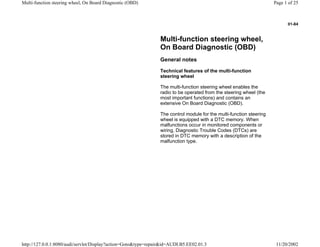
1. 01-84
Multi-function steering wheel,
On Board Diagnostic (OBD)
General notes
Technical features of the multi-function
steering wheel
The multi-function steering wheel enables the
radio to be operated from the steering wheel (the
most important functions) and contains an
extensive On Board Diagnostic (OBD).
The control module for the multi-function steering
wheel is equipped with a DTC memory. When
malfunctions occur in monitored components or
wiring, Diagnostic Trouble Codes (DTCs) are
stored in DTC memory with a description of the
malfunction type.
Page 1 of 25Multi-function steering wheel, On Board Diagnostic (OBD)
11/20/2002http://127.0.0.1:8080/audi/servlet/Display?action=Goto&type=repair&id=AUDI.B5.EE02.01.3
2. 01-85
On Board Diagnostic (OBD), initiating
program
Additional information
Electrical Wiring Diagrams, Troubleshooting &
Component Locations binder
Technical service handbook.
Parts catalog
Page 2 of 25Multi-function steering wheel, On Board Diagnostic (OBD)
11/20/2002http://127.0.0.1:8080/audi/servlet/Display?action=Goto&type=repair&id=AUDI.B5.EE02.01.3
3. 01-86
Safety precautions
If special testing equipment is required
during test drive, note the following:
WARNING!
To reduce the risk of accidents observe the
following:
During a road test in an airbag-equipped
vehicle, the VAS5051 tester or the VAG1551
scan tool must always be fastened to and
operated from the rear seat by a second
technician.
Page 3 of 25Multi-function steering wheel, On Board Diagnostic (OBD)
11/20/2002http://127.0.0.1:8080/audi/servlet/Display?action=Goto&type=repair&id=AUDI.B5.EE02.01.3
4. 01-87
To reduce the risk of injury to people and or
damage to the electrical system and
components, observe the following:
Always switch ignition off before connecting or
disconnecting test/measurement tools.
It is possible that the control module will
recognize a malfunction and store a DTC during
some tests. Therefore, after completing all tests
and repairs, check and if necessary erase the
DTC memory.
Always switch ignition off before disconnecting
or connecting the battery. Failure to do so may
damage a control module.
Page 4 of 25Multi-function steering wheel, On Board Diagnostic (OBD)
11/20/2002http://127.0.0.1:8080/audi/servlet/Display?action=Goto&type=repair&id=AUDI.B5.EE02.01.3
5. 01-88
Test requirements
Check fuse for function according to wiring
diagram.
Connect VAS5051 tester or VAG1551 scan tool
page 01-108 .
Switch ignition on.
Notes:
If nothing is indicated on display, check voltage
supply for VAG 1551 scan tool according to
wiring diagram.
Additional instructions can be called up via the
HELP button on the scan tool.
The button is used for advancing through the
program sequence.
An incorrect entry can be canceled using the C
button.
Function 00 "Automatic test sequence" can be
performed in operating mode 1 "Rapid data
transfer". This automatically checks all control
Page 5 of 25Multi-function steering wheel, On Board Diagnostic (OBD)
11/20/2002http://127.0.0.1:8080/audi/servlet/Display?action=Goto&type=repair&id=AUDI.B5.EE02.01.3
6. modules installed in the vehicle.
Page 6 of 25Multi-function steering wheel, On Board Diagnostic (OBD)
11/20/2002http://127.0.0.1:8080/audi/servlet/Display?action=Goto&type=repair&id=AUDI.B5.EE02.01.3
7. 01-89
- Switch ignition on.
- Switch printer on via the PRINT button (indicator
lamp in button lights up).
- Press button -1- to select "Rapid data transfer"
operating mode 1.
Rapid data transfer HELP
Insert address word XX
Indicated on display
Address word for steering wheel electronics: 16
- Press buttons -1- and -6-.
Rapid data transfer Q
16 - Steering wheel electronics
Indicated on display
- Press -Q- button to confirm input.
Page 7 of 25Multi-function steering wheel, On Board Diagnostic (OBD)
11/20/2002http://127.0.0.1:8080/audi/servlet/Display?action=Goto&type=repair&id=AUDI.B5.EE02.01.3
8. 01-90
4B0907487E Steering whl. electronics D00
Indicated on display after approx. 5 seconds:
4B0907487 E: Part number of steering wheel electronics - radio
operation (see also parts catalog)
Steering wheel electronics: component marking
D00: Software version of control module
- Press button.
Rapid data transfer HELP
Control module does not answer
If one of these messages is displayed, carry out trouble shooting
procedures according to the wiring diagram.
Electrical Wiring Diagrams, Troubleshooting & Component Locations
Rapid data transfer HELP
Error in communication link
Rapid data transfer HELP
K wire not switching to Ground
Rapid data transfer HELP
K wire not switching to B+
Page 8 of 25Multi-function steering wheel, On Board Diagnostic (OBD)
11/20/2002http://127.0.0.1:8080/audi/servlet/Display?action=Goto&type=repair&id=AUDI.B5.EE02.01.3
9. 01-91
Rapid data transfer HELP
Select function XX
Indicated on display
On Board Diagnostic (OBD) functions
The following functions are possible:
01 - Check Control Module Versions page 01-92 .
02 - Check DTC Memory page 01-93 .
03 - Output Diagnostic Test Mode page 01-97 .
05 - Erase DTC Memory page 01-100 .
06 - End Output page 01-102 .
08 - Read Measuring Value Block page 01-103 .
- Pressing the HELP button will print out an overview of all of the
possible functions.
- Press the button to continue program sequence.
Page 9 of 25Multi-function steering wheel, On Board Diagnostic (OBD)
11/20/2002http://127.0.0.1:8080/audi/servlet/Display?action=Goto&type=repair&id=AUDI.B5.EE02.01.3
10. 01-92
Check Control Module Versions (scan
tool function 01)
Rapid data transfer HELP
Select function XX
Indicated on display
- Press buttons -0- and 1-. This selects "Check control module" function
01.
Rapid data transfer Q
01 - Check Control Module Versions
Indicated on display
- Confirm input using the -Q- button.
4B0907487E steering whl. electronics D00
Indicated on display after approx. 5 seconds:
4B0907487 E: Part number of steering wheel electronics - radio
operation (see also parts catalog)
Steering wheel electronics: component marking
D00: Software version of control module
- Press button.
Page 10 of 25Multi-function steering wheel, On Board Diagnostic (OBD)
11/20/2002http://127.0.0.1:8080/audi/servlet/Display?action=Goto&type=repair&id=AUDI.B5.EE02.01.3
11. 01-93
Check DTC Memory (scan tool function
02)
Note:
The displayed DTC information is updated only
when initiating OBD or with "Erase DTC Memory"
function 05.
- Switch printer on via the PRINT button (indicator
lamp in button lights up).
Rapid data transfer HELP
Select function XX
Indicated on display
- Press buttons -0- and -2-. This selects "Check DTC memory", function
02.
Rapid data transfer Q
02 - Check DTC Memory
Indicated on display
- Confirm input using the -Q- button.
X DTC recognized The number of stored malfunctions appears in the display.
The stored malfunctions are displayed and printed out one after the
other.
- Check printout against DTC table and repair all malfunctions as
necessary page 01-95 .
Page 11 of 25Multi-function steering wheel, On Board Diagnostic (OBD)
11/20/2002http://127.0.0.1:8080/audi/servlet/Display?action=Goto&type=repair&id=AUDI.B5.EE02.01.3
12. 01-94
No DTC recognized If "No DTC recognized" is displayed, the program will return to "Select
function XX" after the button is pressed.
Rapid data transfer HELP
Select function XX
Indicated on display
If something else is displayed:
Scan Tool operating instructions
- End output (Function 06) page 01-102
- Switch off ignition and disconnect diagnostic connector.
Page 12 of 25Multi-function steering wheel, On Board Diagnostic (OBD)
11/20/2002http://127.0.0.1:8080/audi/servlet/Display?action=Goto&type=repair&id=AUDI.B5.EE02.01.3
13. 01-95
Diagnostic Trouble Code (DTC) table
Notes:
The following list contains all malfunctions that can be recognized by the multi-function steering wheel and printed out by
the VAG1551 scan tool. The malfunctions are listed in order according to their 5-digit numbers.
DTC numbers appear only on the print-out.
Before replacing a component shown as faulty, check the wiring and connections to the component as well as the Ground
(GND) connections according to wiring diagram.
After repairs and function test of the system, DTC memory must always be checked again using the VAG1551 scan tool
and erased.
DTC memory stores all static and sporadic malfunctions: If a malfunction occurs and persists for at least 2 seconds, it is
identified as a static malfunction. If a malfunction does not occur again, it is registered as sporadic. "/SP" will appear at the
right of the scan tool display.
When the ignition is switched on, all existing malfunctions are automatically re-classified as sporadic malfunctions and will
only register as static malfunctions if they still occur after testing.
Sporadic malfunctions which no longer occur during 50 driving cycles (ignition on at least 5 minutes, vehicle speed 30
km/h) are erased automatically.
The three digit malfunction type number appearing next to the DTC is a data code and can be ignored.
Page 13 of 25Multi-function steering wheel, On Board Diagnostic (OBD)
11/20/2002http://127.0.0.1:8080/audi/servlet/Display?action=Goto&type=repair&id=AUDI.B5.EE02.01.3
14. 01-96
DTC
VAG1551 scan tool
display
Possible cause Corrective action
01426
Control unit in steering
wheel -E221
No communication
Implausible signal
Open circuit in wiring - no connection between
interface and steering wheel
Unintelligible messages on CAN-bus (interface and
buttons in steering wheel are connected via a CAN-
bus)
Electrical Wiring Diagrams,
Troubleshooting & Component
Locations
- Locate malfunction using wiring
diagram
- Repair open circuit
- Check wires between interface and
steering wheel
65535
Control module
malfunctioning
Faulty
Control module for multi-function steering wheel -
J453- faulty
- Replace control module for multi-
function steering wheel -J453-
Page 14 of 25Multi-function steering wheel, On Board Diagnostic (OBD)
11/20/2002http://127.0.0.1:8080/audi/servlet/Display?action=Goto&type=repair&id=AUDI.B5.EE02.01.3
15. 01-97
Output Diagnostic Test Mode (DTM)
(scan tool function 03)
Notes:
Output Diagnostic Test Mode is only possible
when vehicle is stationary and engine is not
running!
If malfunctions are found during output
Diagnostic Test Mode, determine cause of
malfunction and repair if necessary.
In the function " output Diagnostic Test Mode
(DTM)" functions of the system are checked
Perform Output Diagnostic Test Mode
- Switch ignition on.
- Switch on radio.
- Press buttons -0- and -3-. This selects "output
Diagnostic Test Mode (DTM)", function 3.
Rapid data transfer Q
03 - Output Diagnostic Test Mode
Indicated on display
- Press -Q- button to confirm input.
Page 15 of 25Multi-function steering wheel, On Board Diagnostic (OBD)
11/20/2002http://127.0.0.1:8080/audi/servlet/Display?action=Goto&type=repair&id=AUDI.B5.EE02.01.3
16. 01-98
- Press the button.
Output Diagnostic Test Mode
Radio louder
Indicated on display
The radio volume is increased audibly.
- Press the button.
Output Diagnostic Test Mode
Radio quieter
Indicated on display
The radio volume is decreased audibly.
- Press the button.
Output Diagnostic Test Mode
Search radio stations upward
Indicated on display
The next station will be searched and displayed in combination center
display.
- Press the button.
Page 16 of 25Multi-function steering wheel, On Board Diagnostic (OBD)
11/20/2002http://127.0.0.1:8080/audi/servlet/Display?action=Goto&type=repair&id=AUDI.B5.EE02.01.3
17. 01-99
Output Diagnostic Test Mode
Search radio stations downward
Indicated on display
The previous station will be adjusted again and will be displayed in
combination center display.
- Press the button.
Output Diagnostic Test Mode
End
Indicated on display
- Press the button.
- The tester returns to the "Select function" mode.
Rapid data transfer HELP
Select function XX
Indicated on display
Page 17 of 25Multi-function steering wheel, On Board Diagnostic (OBD)
11/20/2002http://127.0.0.1:8080/audi/servlet/Display?action=Goto&type=repair&id=AUDI.B5.EE02.01.3
18. 01-100
Erase DTC Memory (scan tool function
05)
Note:
If DTC memory cannot be erased, check DTC
memory again and repair malfunction.
Requirements
DTC memory checked page 01-93
All malfunctions repaired
After successful DTC memory check:
Rapid data transfer HELP
Select function XX
Indicated on display
- Press buttons -0- and -5-. This selects "Erase DTC memory", function
05.
Page 18 of 25Multi-function steering wheel, On Board Diagnostic (OBD)
11/20/2002http://127.0.0.1:8080/audi/servlet/Display?action=Goto&type=repair&id=AUDI.B5.EE02.01.3
19. 01-101
Rapid data transfer Q
05 Erase DTC Memory
Indicated on display
- Confirm input using the -Q- button.
Rapid data transfer
DTC Memory is erased!
Indicated on display
DTC memory is erased.
- Press the button.
Rapid data transfer HELP
Select function XX
Indicated on display
Notes:
Attention!
DTC Memory was not interrogated
This message indicates an error in the test sequence.
Rapid data transfer
DTC Memory was not interrogated
Follow test sequence exactly: first check DTC memory, repair malfunction
(s) if necessary, then erase.
This message indicates an error in the test sequence.
Page 19 of 25Multi-function steering wheel, On Board Diagnostic (OBD)
11/20/2002http://127.0.0.1:8080/audi/servlet/Display?action=Goto&type=repair&id=AUDI.B5.EE02.01.3
20. 01-102
End Output (scan tool function 06)
- Press buttons -0- and -6-. This selects "End
Output", function 06.
Rapid data transfer Q
06 - End output
Indicated on display
- Confirm input using the -Q- button.
Rapid data transfer HELP
Insert address word XX
Indicated on display
- Switch ignition off.
- Disconnect harness connectors for the VAG1551 scan tool
Page 20 of 25Multi-function steering wheel, On Board Diagnostic (OBD)
11/20/2002http://127.0.0.1:8080/audi/servlet/Display?action=Goto&type=repair&id=AUDI.B5.EE02.01.3
21. 01-103
Read Measuring Value Block (scan tool
function 08)
Initiating "Read Measuring Value Block"
Rapid data transfer HELP
Select function XX
Indicated on display
- Press buttons -0- and -8- to select "Read Measuring Value Block"
function 08.
Rapid data transfer Q
08 - Read Measuring Value Block
Indicated on display
- Confirm input using the -Q- button.
Read Measuring Value Block
Input display group number XXX
Indicated on display
The selected measuring value block is now displayed in standard form.
- Input display group number (from table page 01-104 ) and press -Q-
button to confirm input.
Page 21 of 25Multi-function steering wheel, On Board Diagnostic (OBD)
11/20/2002http://127.0.0.1:8080/audi/servlet/Display?action=Goto&type=repair&id=AUDI.B5.EE02.01.3
22. 01-104
Display group overview
Display group
number
Indicated on display
001 1 = Lower button
2 = Louder button
3 = Memory downward
button
4 = Memory upward button
002 1 = Station buttons (preset)
backward
2 = Station buttons (preset)
forward
3 = Unassigned
4 = Unassigned
Page 22 of 25Multi-function steering wheel, On Board Diagnostic (OBD)
11/20/2002http://127.0.0.1:8080/audi/servlet/Display?action=Goto&type=repair&id=AUDI.B5.EE02.01.3
23. 01-105
Measuring value block 001
Read Measuring Value Block 1 Indicated on display:
lower louder Memory backward Memory upward
Memory upward button
not operated
Memory upward
Memory downward button
not operated
Memory downward
Louder-button (increasing volume)
not operated
louder
Lower button (decreasing volume)
not operated
lower
Page 23 of 25Multi-function steering wheel, On Board Diagnostic (OBD)
11/20/2002http://127.0.0.1:8080/audi/servlet/Display?action=Goto&type=repair&id=AUDI.B5.EE02.01.3
24. 01-106
Measuring value block 002
Read Measuring Value Block 2 Indicated on display:
activated activated
Station buttons (preset) forward
not operated
operated
Station buttons (preset) backward
not operated
operated
Page 24 of 25Multi-function steering wheel, On Board Diagnostic (OBD)
11/20/2002http://127.0.0.1:8080/audi/servlet/Display?action=Goto&type=repair&id=AUDI.B5.EE02.01.3
25. 01-107
Multi-function steering wheel button
assignment
Radio button assignment
1 - Radio: Forward search function; Cassette: Fast forward; CD: Title
forward
2 - Radio: Backward search function; Cassette: Rewind; CD: Title
backward
3 - Station buttons (preset) b backward
4 - Increase volume
5 - Decrease volume
6 - Station buttons (preset) forward
Page 25 of 25Multi-function steering wheel, On Board Diagnostic (OBD)
11/20/2002http://127.0.0.1:8080/audi/servlet/Display?action=Goto&type=repair&id=AUDI.B5.EE02.01.3