The document is the user manual for the Altivar 12 variable speed drive for asynchronous motors. It contains general descriptions and technical characteristics of the drive's performance. The manual is not intended as a substitute for determining suitability or reliability of the drive for specific applications. Safety regulations must be observed when installing and using the drive. Only the manufacturer should perform repairs to ensure safety and compliance. Failure to use approved software may result in injury or improper operation.
The document provides information on the drive's ratings, dimensions, mounting instructions, wiring details, terminal descriptions, factory configuration, basic functions, programming structure, compatibility, and maintenance procedures. It also includes application notes on energy savings possible with the drive and a parameter index for reference.

![BBV28581 05/2013 3
Contents
Contents ____________________________________________________________________________________________________ 3
Important information __________________________________________________________________________________________ 4
Before you begin______________________________________________________________________________________________ 5
Documentation structure________________________________________________________________________________________ 7
Software enhancements________________________________________________________________________________________ 8
Steps for setting up (also refer to Quick Start) _______________________________________________________________________ 9
Setup - Preliminary recommendations ____________________________________________________________________________ 10
Drive ratings ________________________________________________________________________________________________ 11
Dimensions and weights_______________________________________________________________________________________ 12
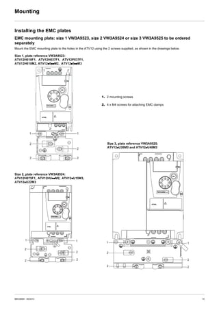
Mounting___________________________________________________________________________________________________ 13
Wiring _____________________________________________________________________________________________________ 16
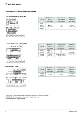
Power terminals _____________________________________________________________________________________________ 20
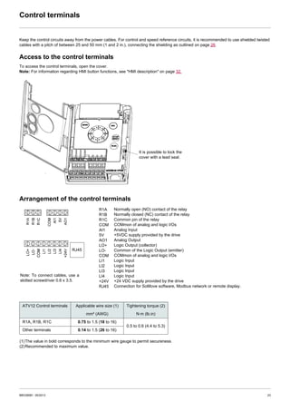
Control terminals_____________________________________________________________________________________________ 23
Check list __________________________________________________________________________________________________ 29
Factory configuration _________________________________________________________________________________________ 30
Basic functions ______________________________________________________________________________________________ 31
Programming _______________________________________________________________________________________________ 32
Structure of parameter tables ___________________________________________________________________________________ 35
Function compatibility table ____________________________________________________________________________________ 36
Reference Mode rEF _________________________________________________________________________________________ 37
Monitoring mode MOn ________________________________________________________________________________________ 38
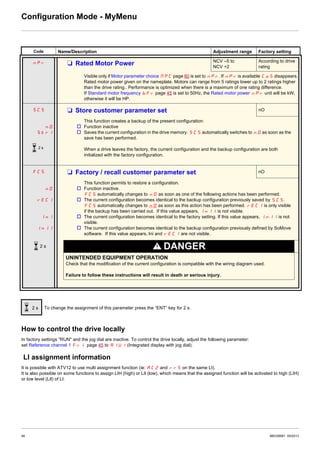
Configuration Mode ConF______________________________________________________________________________________ 44
Configuration Mode - MyMenu __________________________________________________________________________________ 45
Configuration Mode - Complete menu (FULL) ______________________________________________________________________ 47
Maintenance _______________________________________________________________________________________________ 100
Migration ATV11 - ATV12_____________________________________________________________________________________ 101
Diagnostics and Troubleshooting _______________________________________________________________________________ 108
Application notes ___________________________________________________________________________________________ 114
Short-circuit rating and branch circuit protection ___________________________________________________________________ 120
Organization tree ___________________________________________________________________________________________ 121
Parameter index ____________________________________________________________________________________________ 122
Energy savings
Speed control process regulating enables significant energy savings, particulary with pump and fan applications.
Furthermore some ATV12 functions enable to enhance these savings: [Motor control type] (Ctt) page 57, [Sleep/wake]
(tLS) page 74 and [PID feedback assignment] (PIF) page 72.](https://image.slidesharecdn.com/atv12-200126173130/85/Atv12-3-320.jpg)


![34 BBV28581 05/2013
Programming
First power-up
At first power-up you are prompted to set Standard motor frequency bFr page 45. Next time power is applied rdY appears. Operating
mode selection is then possible using the MODE key as detailed below.
Menus structure
Access to menus and parameters is possible through 3 modes: Reference rEF page 37, Monitoring MOn page 38 and Configuration
COnF page 44. Switching between these modes is possible at any time using the MODE key or Jog Dial on keyboard. The first press on
the MODE key moves from the current position to the top of the branch. A second press switches to the next mode.
Menu customization using SoMove
ATV12 factory settings enable drive operation with most applications. You can use SoMove software to customize the "MyMenu" and FULL
menus of COnF mode (see page 44), by selecting which menus and parameters will be hidden or accessible for the user. Once the
configuration has been adjusted, it can be downloaded to the ATV12 by connecting the drive to the computer or by downloading the
configuration through the multiloader or simpleloader.
SoMove can be used to operate the drive for testing and commissioning.
For further information, please consult the SoMove help.
Description References
SoMove -
USB/RJ45 cable TCSMCNAM3M002P
Simple-loader tool VW3A8120
Multi-loader tool VW3A8121
Bluetooth adapter VW3A8114
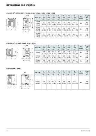
COnFMOnrEF
LOC
35.
rdY
rEN
3s
MODE
3s
MODE
2s
ESC
rdY
ESC ENT
ESCESC
ESC
[SPEED REFERENCE] [MONITORING] [CONFIGURATION]
MODE MODE MODE
[REMOTE configuration] [LOCAL configuration]
[Analog input virtual
(Hz)]](https://image.slidesharecdn.com/atv12-200126173130/85/Atv12-34-320.jpg)


![[量子コンピューター勉強会資料] マヨラナ粒子によるスケーラブルな量子コンピューターの設計](https://cdn.slidesharecdn.com/ss_thumbnails/20180315microsoftquantumdevice-180317073848-thumbnail.jpg?width=640&height=640&fit=bounds)


