Download to read offline


![Atmospheric Crude Tower R1-9
R1-9
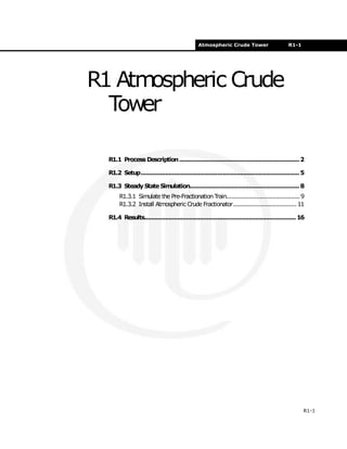
R1.3.1 Simulate the Pre-
Fractionation Train
Inlet Stream
Specify the Inlet stream (Raw Crude) as shown below.
Because the composition has been transferred from the Oil
Characterization, the stream is automatically flashed.
Pre-Flash Operations
Install the Separator, Heater, and Mixer and provide the
information displayed below:
Stream [Raw Crude]
In this cell... Enter...
Temperature [F] 450.0°F
Pressure [psia] 75.0 psia
Std Ideal Liq Vol Flow [barrel/day] 100,000 barrel/day
Separator [PreFlash]
Tab [Page] In this cell... Enter...
Design
[Connections]
Inlet Raw Crude
Vapour Outlet PreFlash Vap
Liquid Outlet PreFlash Liq
Heater [Crude Heater]
Tab [Page] In this cell... Enter...
Design
[Connections]
Inlet PreFlash Liq
Outlet Hot Crude
Energy Crude Duty
Design [Parameters] Delta P 10.00 psi
Worksheet
[Conditions]
Temperature (Hot Crude) 650 °F](https://image.slidesharecdn.com/atmosphericcrudetower-180803121950/85/Atmospheric-crude-tower-simulation-9-320.jpg)
![R1-10 Steady State Simulation
R1-10
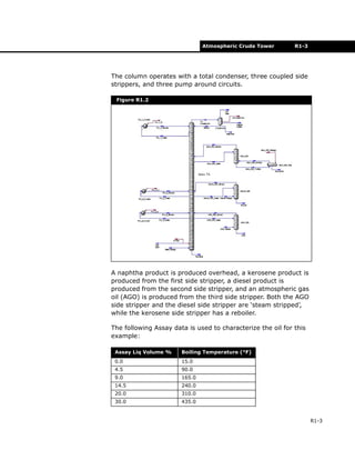
The calculated specifications for the Pre-Fractionation Atm Feed
stream appear below.
The Pre-Fractionation train is shown as follows:
Mixer [Mixer]
Tab [Page] In this cell... Enter...
Design
[Connections]
Inlets Hot Crude, PreFlash Vap
Outlet Atm Feed
Figure R1.7
Figure R1.8](https://image.slidesharecdn.com/atmosphericcrudetower-180803121950/85/Atmospheric-crude-tower-simulation-10-320.jpg)
![Atmospheric Crude Tower R1-11
R1-11
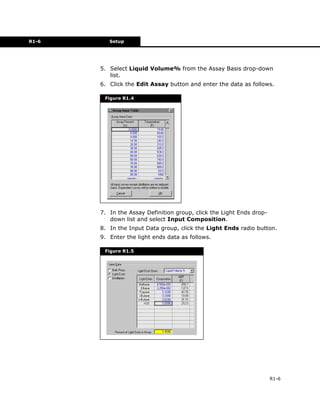
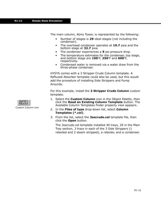
R1.3.2 Install Atmospheric
Crude Fractionator
Steamand TrimDuty Streams
Before simulating the atmospheric crude tower, the steam feeds
and the energy stream (Q-Trim - representing the side
exchanger on stage 28) to the column must be defined.
The Q-Trim stream does not require any specifications, this will
be calculated by the Column.
Three steam streams are fed to various locations in the tower.
Specify the steam streams as shown below. Define the
composition for each as H2O = 1.0000.
These streams could be installed inside the Column Build
Environment as well. By taking this approach, you will need
to “attach” these streams to the Column Flowsheet so that
they can be used in the calculations.
Column
In this application, the Input Experts option have been turned
off, and the Column is being configured directly through the
Column property view.
An energy stream can be installed by selecting the
appropriate icon from the palette, or a material stream
converted to an energy stream on the Util page of the stream
property view.
Stream Name Temperature [F] Pressure [psia] Mass Flow [lb/hr]
Main Steam 375.00 150.00 7500.00
Diesel Steam 300.00 50.00 3000.00
AGO Steam 300.00 50.00 2500.00](https://image.slidesharecdn.com/atmosphericcrudetower-180803121950/85/Atmospheric-crude-tower-simulation-11-320.jpg)
![R1-14 Steady State Simulation
R1-14
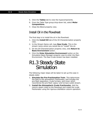
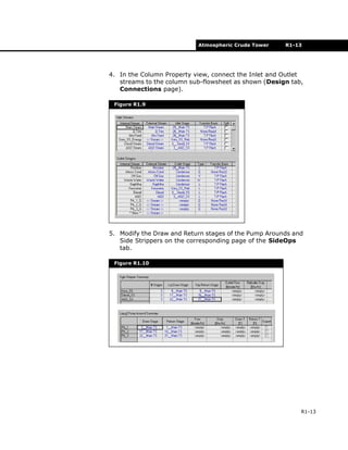
6. In the Atmos Tower Column property view, specify the
column information below.
Field units are used for column preferences.
Specifications
On the Monitor page of the Design tab, make the following
changes and input the values into the default set of
specifications supplied with the pre-built 3-Side Stripper
Column.
1. Change all the Pump Around delta T specifications to a
Duty specification.
2. Delete the Kero SS BoilUp Ratio and the Residue Rate
specs.
Open the specification property view by clicking the View
button, then click Delete to delete the specification.
3. Specify the Reflux Ratio spec to have a value of 1. Clear
the Reflux Ratio Active checkbox and make it an Estimate
only.
4. Change the following default specifications by selecting the
specification in the table and clicking the View button.
Change the Flow Basis to Std Ideal Volume before entering
values.
Column [Atms Tower]
Tab [Page] In this cell... Enter...
Parameters
[Profiles]
Condenser Pressure 19.7 psia
29_Main TS Pressure 32.7 psia
Condenser Temperature 100°F
1_Main TS Temperature 250°F
29_Main TS Temperature 600°F
Specification Flow Basis Spec Type Spec Value
Kero_SS Prod Flow Volume 9300 barrel/day
Diesel_SS Prod Flow Volume 1.925e+04 barrel/day
AGO_SS Prod Flow Volume 4500 barrel/day
PA_1_Rate(Pa) Volume 5.000e+04 barrel/day
PA_1_Duty(Pa) Duty -5.500e+07 Btu/hr](https://image.slidesharecdn.com/atmosphericcrudetower-180803121950/85/Atmospheric-crude-tower-simulation-14-320.jpg)
![R1-16 Results
R1-16
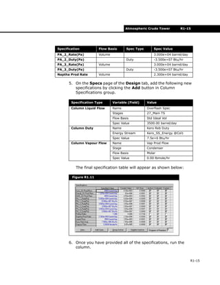
R1.4 Results
Workbook Case (Main)
The material stream results for the Workbook Case[Main]
appear below.
Figure R1.12](https://image.slidesharecdn.com/atmosphericcrudetower-180803121950/85/Atmospheric-crude-tower-simulation-16-320.jpg)
![Atmospheric Crude Tower R1-17
R1-17
Workbook Case (Atms Tower)
The material stream results for the Workbook Case [Atms
Tower] appear below.
Figure R1.13](https://image.slidesharecdn.com/atmosphericcrudetower-180803121950/85/Atmospheric-crude-tower-simulation-17-320.jpg)

The document describes setting up and simulating an atmospheric crude distillation column in HYSYS. It involves characterizing the crude oil feed using assay data, installing a pre-fractionation train with a separator, heater and mixer to determine the feed to the column, and then installing the column along with defining steam and energy streams. The column is configured as a 29 stage ideal column with overhead, bottoms and side product draws using a built-in 3 stripper crude column template.


