1) Several institutions have tested novel propulsion devices called EM Drives and Cannae Drives that produce thrust without propellant by using resonant microwave cavities. Results have ranged from 0.02 N/kW to 1.03 N/kW of thrust.
2) The document analyzes differences between experiments such as cavity design, materials, power levels, measurement techniques, and number of test runs. It finds variations in these factors likely contributed to differing results.
3) Specifically, NASA JSC Eagleworks obtained the lowest thrust of 0.0021 N/kW using a tapered cylindrical cavity with a dielectric insert, while other experiments excluding Tajmar obtained over 0.1 N/kW
![5
American Institute of Aeronautics and Astronautics
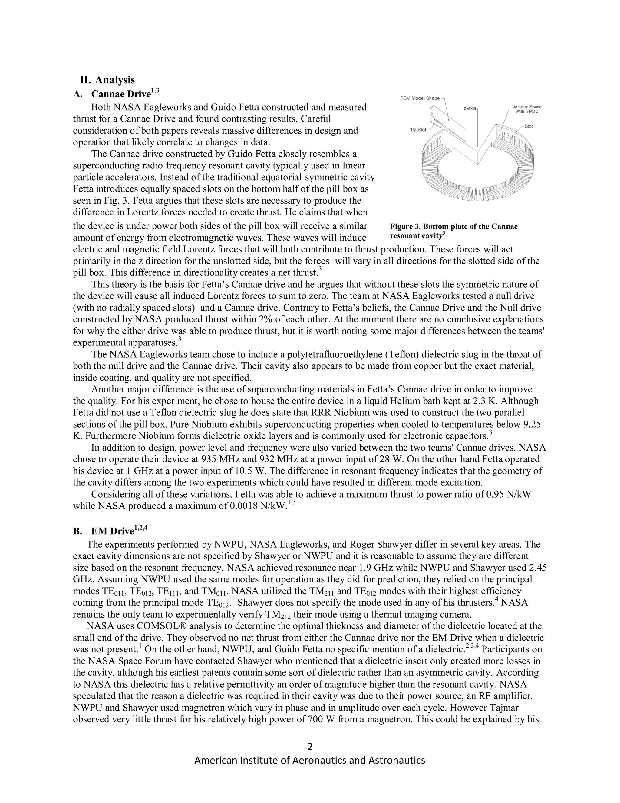
power is increased for two test runs: 300 W to 2500 W, and 80 W to 1200 W. During the first experiment, a thrust
of 310 mN was observed for an input power of 300 W. As the power was increased to 800 W the thrust decreased to
160 mN. Finally the thrust increased to 750 mN as the power was brought to 2500 W.2
During the second experiment, a thrust of 270 mN was observed at 300 W; thrust then decreased to 180 mN at
600 W. As the power was increased to 1200 W the thrust increased to 250 mN. The plots in Fig. 6 show the non
linear nature of thrust versus input power. Further analysis was performed on the magnetron output to determine that
the nominal output powers of 200, 300, 400, 500, 600 and 700 W actually produced practical powers of 13, 120, 85,
65, 45, and 48 W respectively. Correcting for this relation shows that the EM thrust increases with practical power
increase. Although the predicted and observed trends agree, the calculations done by NWPU are not consistent with
experimental results. This error is attributed to properties of the thruster cavity and magnetron frequency spectrum.2
It is determined that more than 50% of the microwave power can be absorbed by the resonant cavity to produce
EM thrust when the magnetron frequency is between 2.4492 GHz and 2.4508 GHz. NWPU reports a total error of
12% and a repeatability error of 8% and concludes that microwave energy in a resonant cavity can definitely
produce a net thrust.2
C. Guido Fetta Cannae Drive3
On January 3rd, 2011 Guido Fetta sent 4-5 second pulses of 10.5 W at 1047.335 MHz to
his resonant cavity submerged in liquid helium at 2.3 K. He observed a reduction in compression force on the load
cell corresponding to a thrust of 7-10 mN which can be seen in Fig. 7. The liquid helium was maintained at
equilibrium at 50 Torr
during the first
experiment. Additional
tests seen in Fig. 8
were performed on the
second day with the
liquid helium at a
temperature of 4.2 K,
which resulted in thrust
measurements of 7
mN. The Q-factor was
measured to be 1.08E7
and only marginally varied between 2.3 K and 4.2 K. The stored power in the cavity
was determined to be 7.73 E-3 Joules.3
Numerical prediction indicated a net Lorentz force of 16.7 mN at this energy
level. The error is attributed to limitations in the measured Q-factor, the data available
to calculate stored energy, and the load cell sensitivity. Cannae plans to test a new,
larger cavity with improved geometry and signal-port design.3
D. Roger Shawyer at Satellite Propulsion Research Ltd.4
Shawyer began his first test of the EM drive in 2001 and has since tested a
number of variations of the thruster. For his first test, an engine was constructed with
a maximum diameter of 160 mm and an operating frequency of 2.45 GHz. Measurements showed that the Q-factor
for this device was 5,900. When a power of 850 W was applied a mean thrust of 16mN was measured which was
within 4% of the predicted thrust output. Overall, Shawyer conducted 450 test runs with periods of up to 50 seconds,
using 5 different magnetrons. A second engine, known as the Demonstrator Engine, was developed in 2003. This
engine had a maximum diameter of 280 mm and operated at a frequency of 2.45 GHz. Measurements showed that
the Q-factor for this device was 45,000 and the design factor was found to be 0.844. A water-cooled magnetron with
a variable power output was used for this engine with a maximum power of 1.2 kW. A total of 134 test runs were
conducted and the maximum thrust to power ratio was found to be 0.243 N/kW at a power of 421 W. In addition to
these two thrusters, Shawyer completed a third engine which he refers to as the Flight Thruster. This thruster was
slightly smaller than the previous generation and featured a maximum diameter of 265 mm and a base-plate height
of 164 mm. The frequency of operation was not given for this device but Shawyer does mention that the Flight
Thruster utilizes a frequency tracking algorithm and has been tested up to a power of 600 W. The Flight Thruster
Figure 6. NWPU measured total net EM
thrust at microwave power ranges (a) 300-
2500 W (b) 80-1200 W [2]
Figure 7. Day 1 testing with helium temperature below 3 K [4]
Figure 8. Day 2 testing with helium at 4.2 K [4]](https://image.slidesharecdn.com/423160a4-f122-4fe9-aad4-ad809e0f0acf-160107221046/75/Analysis-of-Anomalous-Thrust-Experiments-from-an-Asymmetric-Cavity-5-2048.jpg)
![7
American Institute of Aeronautics and Astronautics
5
Tajmar, M., Fiedler, G., "Direct Thrust Measurements of an EM Drive and Evaluation of Possible Side-Effects" Dresden
University of Technology, Germany
6
Dristler, D., "Microwave Energy Injection into a Conical Frustum: The NSF-1701 Phase I Test Report", Chagrin Fall,
OH.
7
Wang B., "Update on EM Drive Work at NASA Eagleworks", 3 Feb 2015, URL:
http://nextbigfuture.com/2015/02/update-on-emdrive-work-at-nasa.html [cited 28 March 2015]](https://image.slidesharecdn.com/423160a4-f122-4fe9-aad4-ad809e0f0acf-160107221046/75/Analysis-of-Anomalous-Thrust-Experiments-from-an-Asymmetric-Cavity-7-2048.jpg)


![1386 voronka[1]](https://cdn.slidesharecdn.com/ss_thumbnails/qkt2almft6oweros0u9t-signature-af3363fef01d0d7c45588ce8355ebf87395936210cee8c9809ea3a5b098ac2cc-poli-140825181820-phpapp01-thumbnail.jpg?width=640&height=640&fit=bounds)


![1159 voronka[1]](https://cdn.slidesharecdn.com/ss_thumbnails/u6ur9dkkroaacb6r2m1z-signature-fabe374f978bfb273f92443e2c8243d3e294d623a7c677008fe136d7284f57a9-poli-140825181532-phpapp01-thumbnail.jpg?width=640&height=640&fit=bounds)


