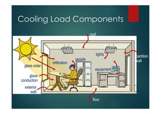
AIR CONDITIONING
LOAD CALCULATION
PSME-Qatar
Members Development
Program
OBJECTIVE
The Main Objective of this Presentation
is to Provide the Participants Working
Knowledge in the Field of Air
Conditioning System Load Calculation
for Residential Commercial and
Industrial Buildings
Principles of Heat Transfer
Heat energy cannot be destroyed.
Heat always flows from a higher
temperature substance to a lower
temperature substance.
Heat can be transferred from one
substance to another.
Methods of Heat Transfer
convection
convection
radiation
radiation
hot
water
hot
water
conduction
conduction cool air
cool air
Conduction, Convection & Radiation
Measuring Heat Quantity
60°F 61°F
15°C 16°C
1 Btu
1 kcal
[4.19 kJ]
1 lb
Water
1 kg
Water
What is BTU?
 BTU refers to British Thermal Unit.
 Unit of Heat Energy in Imperial System
or I-P System.
 1 BTU is the amount of Heat energy
required to raise the temperature of 1
lb water by 1⁰F.
WHAT IS AIR
CONDITIONING ?
Air Conditioning is …..
“The Science and Practice of Creating a
Controlled Climate in the Indoor Living or
Working Areas for Comfort of Human Beings
or Animals or for the Proper Performance of
Some Industrial or Scientific Process.”
Human Comfort
Conditions at which most people are likely to feel
comfortable most of the time.
Also called as Thermal Comfort.
Temperature: 78⁰F (Summer) – 68⁰F(Winter).
Relative Humidity: 30 %– 60%.
Indoor Design Conditions
Dry-bulb Temperature
Humidity
Ratio
80°F
[26.7°C]
80°F
[26.7°C]
70°F
[21.2°C]
70°F
[21.2°C]
comfort zone
A
A
Factors Affecting Human
Comfort
 Dry-bulb temperature
 Humidity
 Air movement
 Fresh air
 Clean air
 Noise level
 Adequate lighting
 Proper furniture and
work surfaces
 Provide information for Equipment
Selection and HVAC System Design.
 Provide data for evaluation of
optimum possibilities for Load
Reduction.
 Permit analysis of partial loads as
required for system design,
operation and control.
PURPOSE OF LOAD
CALCULATION.
Heat Gain Or Loss
Cooling Load Or Heating Load
Heat Extraction Or Heat
Addition
PRINCIPLE OF COOLING
LOADS
 Or Instantaneous Rate Of Heat Gain
 Is The Rate Of Which Heat Enters Or
Generated Within A Space At A Given
Instant Of Time.
HEAT GAIN:
TYPES OF HEAT GAIN
 SENSIBLE HEAT GAIN
 LATENT HEAT GAIN
Sensible Vs Latent Heat
60°F
[15.6°C]
212°F
[100°C]
212°F
[100°C]
212°F
[100°C]
Sensible Heat
Latent Heat
WHAT IS SPACE
COOLING LOAD ?
 Rate of the Heat Removal from the
Conditioned Space that has to be
Maintained in Order to Provide the
Desired Inside Condition.
Cooling Load Components
roof
lights
equipment
floor
exterior
wall
glass solar
glass
conduction
infiltration
people
partition
wall
COOLING LOADS
CATEGORY
 External Loads (Due external Factors)
 Internal Loads
 Infiltration and Ventilation Loads
EXTERNAL LOADS:
 Combined Effect of Outdoor Air Temperature and the
Solar Radiation that causes Heat Flow through Roof
and External Walls.
 Temperature of Adjoining Spaces that Causes Heat
Conduction into Conditioned Space thru Interior
Partitions, Ceilings, Floors & Windows.
 Solar Heat Gain by Direct or Indirect Solar Radiation
Thru Windows or other Fenestration Materials.
INTERNAL LOADS
 Lights
 People
 Internal Equipment ( such as, Electrical,
Gas Or Steam appliances, Electrical
machines and other miscellaneous
source of heat & steam.
Infiltration and Ventilation
 Ventilation Is Supplied to Meet the
Required Air Purity and Odor Standards.
 Infiltration Arises From Controlled or
Uncontrolled Leakage Around Doors and
Windows or Through Walls.
AIR CONDITIONING
COOLING LOAD
CALCULATION
PROCEDURES
STEPS INVOLVE IN A/C LOAD
CALCULATION:
 DATA GATHERING
 SELECTION OF INDOOR & OUTDOOR DESIGN
CONDITIONS.
 CALCULATION OF HEAT TRANSFER COFFICIENTS
 CALCULATION OF SPACE COOLING LOAD
 PSYCHROMETRIC ANALYSIS
DATA GATHERING
 Orientation and Dimension of Building
Components.
 Construction Materials for Roof, Walls, Ceiling,
Interior Partitions, Floors and Fenestration.
 Size and Use of Space To Be Conditioned.
 Surrounding Conditions Outdoors and in
Adjoining Spaces,
DESIGN CONDITION
 Outdoor Design Condition
 Indoor Design Condition
 Latitude
 Design Month & Design Hour
 Daily Range
External Cooling Load
 Conduction : For Roof, Walls and Glass.
q = U x A x CLTD
 Solar : Glass
q = A x SC x SHGF x CLF
U - VALUE
4.2.3 CMU Wall
ELEMENT CONSTRUCTION RESISTANCE, ft
2
-hr-
F/Btu
1 Outside Surface (15 mph wind) 0.17
2 Cement Plaster, 19mm 0.15
3 CMU, 200mm 1.11
4 Non-Reflective Air Space 0.91
5 Batt Insulation, 50mm 7.08
6 Gypsum Board, 15mm 0.534
7 Inside Surface (still air) 0.68
TOTAL 10.634
U-Value = 1 / 10.634 = 0.094 Btu/ ft
2
-hr-F
CLTD-COOLING LOAD TEMPERATURE DIFFERENCE FOR
ROOF, WALLS & GLASS
A: FOR ROOF
CLTDcorr. = (CLTD+LM) x K + (78-Tr) x (Toa - 85) x f
WHERE:
CLTD = Cooling Load Temp. Diff., refer to ASHRAE GRP=158 Table 3.8.
LM = CLTD correction for Latitude- Month Correction, Table 3.12.
K = Color Adjustment Factor
Tr = Inside Room temperature
Toa = Average Outside Temperature.
F = Adjustment Factor.
B: FOR WALLS:
CLTDcorr. = (CLTD+LM) x K + (78-Tr) x (Toa - 85)
WHERE:
CLTD = Cooling Load Temp. Diff., refer to ASHRAE GRP=158
Table 3.10.
LM = CLTD correction for Latitude-Month Correction, Table 3.12.
K = Color Adjustment Factor
Tr = Inside Room temperature
Toa = Average Outside Temperature.
GLASS SOLAR LOAD
q = A x SC x SHGF x CLF
WHERE:
A = NET GLASS AREA
SC = SHADING COEFFICIENT
SHGF = MAX. SOLAR HEAT GAIN FACTOR
CLF = COOLING LOAD FACTOR
INTERNAL LOAD
1. PEOPLE
q = ( qs per person x no. of person ) +
( ql per person x no. of people )
where :
q = Total Heat Gain from People, Btu/hr)
qs = Sensible heat gain per person, BTU/Hr.
ql = Latent Heat Gain per person, BTU/hr.
TABLE 3 OF ASHRAE 1997 FUNDAMENTALS
RATE OF HEAT GAIN FOR OCCUPANT
DEG
REEOF
ACTIVITY
TYPEO
F
SPACE
SENSIBLEHEAT,
Btu/h
LATENTHEAT,
Btu/h
Seatedatrest Theater 245 105
Seated,verylightwork O
ffices 245 155
M
oderatelyactivework O
ffices 250 200
W
alking,standing O
ffices 250 250
Sedentarywork DiningAreas 275 275
Lightbenchwork Shops 275 475
Lightm
achinework Shops 375 625
Heavywork Shops 580 870
Athletics G
ym
nasium 710 1090
Note:Tabulatedvaluesabovearebasedonroomtem
p.at75FDB.For80FDBroomtem
p.,thetotal heatrem
ains
t He sam
e,butthesensibleheatvaluesshouldbedecreasedby20%
,andthelatentheatvaluesincreasedaccordingly.
2.0 LIGHTING :
QS = 3.41 X W X BF
WHERE:
QS - SENSIBLE COOLING LOAD, BTU/HR.
W - TOTAL LAMP WATTAGE, WATTS.
BF - BALLAST FACTOR.
Average Values of Ballast Factor for
Flourescent Lights
LAMP WATTAGE NO. OF LAMP /FIXTURE BALLAST FACTOR
35 - 40 1 1.30
35 - 40 2 1.20
60 - 75 1 1.30
60 - 75 2 1.20
110 1 1.25
110 2 1.07
160 1 1.15
160 2 1.08
185 - 215 1 1.08
215 2 1.06
Note: For incandescent lighting where ballast is not required, no factor should be added. Unoccupied diversity
factor shall be used only when fraction of lights are switched on during the unoccupied equipment operation
period.
EQUIPMENT LOAD
 POWER EQUIPMENT
 OFFICE EQUIPMENT
 RESTAURANT EQUIPMENT
 HOSPITAL & LABORATORY EQUIPMENT
POWER EQUIPMENT
QS = ( A OR B OR C ) X NO. OF MOTORS.
R e fe rrin g to A S H R A E 1 9 9 7 F u n d a m e n ta ls T a b le 4 - H e a t G a in fro m T yp ic a l E le ctric M o to rs
a re a s fo llo w s:
M O T O R N A M E -
P L A T E O R R A T E D
H P
M O T O R
T Y P E
(A ) M O T O R IN ,
D R IV E N E Q U IP .
IN , B tu /h r
(B ) M O T O R O U T ,
D R IV E N E Q U IP .
IN , B tu /h r
(C ) M O T O R IN , D R IV E N
E Q U IP . O U T , B tu /h r
0 .0 5 S h a d e d P o le 3 6 0 1 3 0 2 4 0
0 .0 8 S h a d e d P o le 5 8 0 2 0 0 3 8 0
S h a d e d P o le 9 0 0 3 2 0 5 9 0
0 .1 6 S h a d e d P o le 1 1 6 0 4 0 0 7 6 0
0 .2 5 S p lit P h as e 1 1 8 0 6 4 0 5 4 0
0 .3 3 S p lit P h as e 1 5 0 0 8 4 0 6 6 0
0 .5 0 S p lit P h as e 2 1 2 0 1 2 7 0 8 5 0
0 .7 5 3 -P h a s e 2 6 5 0 1 9 0 0 7 4 0
1 3 -P h a s e 3 3 9 0 2 5 5 0 8 5 0
1 .5 3 -P h a s e 4 9 6 0 3 8 2 0 1 1 4 0
2 3 -P h a s e 6 4 4 0 5 0 9 0 1 3 5 0
3 3 -P h a s e 9 4 3 0 7 6 4 0 1 7 9 0
5 3 -P h a s e 1 5 5 0 0 1 2 7 0 0 2 7 9 0
7 .5 3 -P h a s e 2 2 7 0 0 1 9 1 0 0 3 6 4 0
1 0 3 -P h a s e 2 9 9 0 0 2 4 5 0 0 4 4 9 0
1 5 3 -P h a s e 4 4 4 0 0 3 8 2 0 0 6 2 1 0
2 0 3 -P h a s e 5 8 5 0 0 5 0 9 0 0 7 6 1 0
2 5 3 -P h a s e 7 2 3 0 0 6 3 6 0 0 8 6 8 0
3 0 3 -P h a s e 8 5 7 0 0 7 6 3 0 0 9 4 4 0
4 0 3 -P h a s e 1 1 4 0 0 0 1 0 2 0 0 0 1 2 6 0 0
5 0 3 -P h a s e 1 4 3 0 0 0 1 2 7 0 0 0 1 5 7 0 0
OFFICE EQUIPMENT
QS = (A) X NO. OF EQUIPMENT
Recommended Rate of Heat Gain from Selected Office Equipment are listed below:
APPLIANCES SIZE
(A) RATE OF HEAT GAIN, Btu/h
(Sensible)
Personal Computer 16 - 640 Kbytes 300 - 1800
Plotter - 214
Laser Printer 8 pages/min. 1025
Letter Quality Printer 30 - 45 char/min 1000
Blue Printer - 3930 - 42700
Printer Terminal - 270 - 600
Copier, large 30 - 67 copies/min. 5800 - 22500
Copier, small 6 - 30 copies/min. 1570 - 5800
Microfilm Reader/Printer - 3920
Electric Typewriter - 230
Coffee Maker 10 cups 3580 sens; 1540 latent
Microwave Oven 28 L 1360
Paper Shredder - 680 - 8250
Water Cooler 30 L/h 5970
Note: Other office equipment not listed above, heat gain should then be referred to Table 9A of ASHRAE 1997
Fundamentals, Chapter 28 and/or manufacturers manual.
RESTAURANT EQUIPMENT
QE = ( QS + QL ) X NO. OF EQUIPMENT
3 .5 .1 R e c o m m e n d e d R a te o f H e a t G a in fr o m R e s ta u r a n t E q u ip m e n t ( w ith o u t h o o d ) L o c a t e d in
C o n d itio n e d A r e a s a r e lis te d b e lo w :
R A T E O F H E A T G A IN , B tu /h
A P P L IA N C E S S IZ E S E N S IB L E L A T E N T
B le n d e r, p e r q u a r t o f c a p a c ity 1 - 4 q t . 1 8 0 9 5
C o ffe e B r e w e r 1 2 c u p s /2 b r n r s 3 7 5 0 1 9 1 0
Ic e M a k e r , la r g e 2 2 0 lb /d a y 9 3 2 0 -
Ic e M a k e r , s m a ll 1 1 0 lb /d a y 6 4 1 0 -
R e fr ig e ra t o r , la r g e 2 5 - 7 4 ft
3
6 6 5 -
R e fr ig e ra t o r , s m a ll 6 - 2 5 f t
3
3 0 0 -
T o a s te r , la r g e p o p - u p 1 0 s lic e s 9 5 9 0 8 5 0 0
T o a s te r , s m a ll p o p - u p 4 s lic e s 4 4 7 0 3 9 6 0
H o t P la te 2 b u r n e r s 1 1 7 0 0 3 4 7 0
3 .5 .2 R e c o m m e n d e d R a te o f H e a t G a in fr o m R e s ta u r a n t E q u ip m e n t ( e x h a u s t h o o d
r e q u ir e d ) L o c a te d in A ir - C o n d itio n e d A r e a s a r e lis te d b e lo w :
R A T E O F H E A T G A IN , B tu / h
A P P L IA N C E S S IZ E S E N S IB L E L A T E N T
F r y e r , d e e p fa t 3 5 - 5 0 lb . o il 1 2 0 0 -
F r y e r , p r e s s u r iz e d 1 3 - 3 3 lb . 5 9 -
G r id d le /g r ill 2 . 5 - 4 .5 ft
2
4 0 0 -
H o t P la te 2 b u r n e r s 3 4 1 0 -
R a n g e 2 - 1 0 b u r n e rs 6 5 9 0 -
N o t e : F o r a d d it io n a l o ffic e e q u ip m e n t n o t lis t e d a b o v e , h e a t g a in s h o u ld th e n b e r e fe r r e d to T a b le 8 o f
A S H R A E 1 9 9 7 F u n d a m e n ta ls , C h a p te r 2 8 a n d /o r m a n u f a c tu r e r s m a n u a l.
VENTILATION LOAD
 VENTILATION STANDARD IS AVAILABLE IN
THE FOLLOWING STANDARD:
1. TABLE 5.3 ASHRAE GRP 158
2. ASHRAE 62.1, Table 6.1
VENTILATION LOADS
qs = 1.1 x CFMoa x ( toa - tm )
where :
CFM oa = outdoor air
toa = Outdoor Dry Bulb Temp.
tm = room dry bulb temp.
VENTILATION LOAD
LATENT LOAD:
ql = 0.7 x CFM oa x ( Woa -Wrm)
Where:
( Woa-Wrm) = Humidity Ratio Difference
between Outdoor Air and indoor air. Use
Psychrometric Chart.
COOLING LOAD
SUMMARY
Summary
Sensible
Load
latent
load
Conduction through roof, walls,
windows, and skylights
Solar radiation through windows, skylights
Conduction through ceiling, interior
partition walls, and floor
People
Lights
Equipment/ Appliances
Infiltration
Ventilation
System Heat Gains
space
load
coil
load
cooling load components
THANK YOU VERY
MUCH FOR YOUR
ATTENTION
LET’S PROCEED TO
ACTUAL
CALCULATION
Design Consideration:
 Location: Doha, Qatar
 Latitude: 25.25 N, 51.57 E
 Outdoor Design Condition:
 115 deg F (46 deg. C), 79 deg F (26 deg C).
 Daily Range: 32 deg F.
 Design Month & Peak Time: August / 4:00PM
SAMPLE VILLA:
COOLING & HEATING LOAD
ESTIMATE SHEET

Air Conditioning Load Calculation Presentation-15-09-2017.pdf

  • 1.
  • 2.
    OBJECTIVE The Main Objectiveof this Presentation is to Provide the Participants Working Knowledge in the Field of Air Conditioning System Load Calculation for Residential Commercial and Industrial Buildings
  • 3.
    Principles of HeatTransfer Heat energy cannot be destroyed. Heat always flows from a higher temperature substance to a lower temperature substance. Heat can be transferred from one substance to another.
  • 4.
    Methods of HeatTransfer convection convection radiation radiation hot water hot water conduction conduction cool air cool air
  • 5.
  • 6.
    Measuring Heat Quantity 60°F61°F 15°C 16°C 1 Btu 1 kcal [4.19 kJ] 1 lb Water 1 kg Water
  • 7.
    What is BTU? BTU refers to British Thermal Unit.  Unit of Heat Energy in Imperial System or I-P System.  1 BTU is the amount of Heat energy required to raise the temperature of 1 lb water by 1⁰F.
  • 8.
    WHAT IS AIR CONDITIONING? Air Conditioning is ….. “The Science and Practice of Creating a Controlled Climate in the Indoor Living or Working Areas for Comfort of Human Beings or Animals or for the Proper Performance of Some Industrial or Scientific Process.”
  • 9.
    Human Comfort Conditions atwhich most people are likely to feel comfortable most of the time. Also called as Thermal Comfort. Temperature: 78⁰F (Summer) – 68⁰F(Winter). Relative Humidity: 30 %– 60%.
  • 10.
    Indoor Design Conditions Dry-bulbTemperature Humidity Ratio 80°F [26.7°C] 80°F [26.7°C] 70°F [21.2°C] 70°F [21.2°C] comfort zone A A
  • 11.
    Factors Affecting Human Comfort Dry-bulb temperature  Humidity  Air movement  Fresh air  Clean air  Noise level  Adequate lighting  Proper furniture and work surfaces
  • 12.
     Provide informationfor Equipment Selection and HVAC System Design.  Provide data for evaluation of optimum possibilities for Load Reduction.  Permit analysis of partial loads as required for system design, operation and control. PURPOSE OF LOAD CALCULATION.
  • 13.
    Heat Gain OrLoss Cooling Load Or Heating Load Heat Extraction Or Heat Addition PRINCIPLE OF COOLING LOADS
  • 14.
     Or InstantaneousRate Of Heat Gain  Is The Rate Of Which Heat Enters Or Generated Within A Space At A Given Instant Of Time. HEAT GAIN:
  • 15.
    TYPES OF HEATGAIN  SENSIBLE HEAT GAIN  LATENT HEAT GAIN
  • 16.
    Sensible Vs LatentHeat 60°F [15.6°C] 212°F [100°C] 212°F [100°C] 212°F [100°C] Sensible Heat Latent Heat
  • 17.
    WHAT IS SPACE COOLINGLOAD ?  Rate of the Heat Removal from the Conditioned Space that has to be Maintained in Order to Provide the Desired Inside Condition.
  • 18.
    Cooling Load Components roof lights equipment floor exterior wall glasssolar glass conduction infiltration people partition wall
  • 19.
    COOLING LOADS CATEGORY  ExternalLoads (Due external Factors)  Internal Loads  Infiltration and Ventilation Loads
  • 20.
    EXTERNAL LOADS:  CombinedEffect of Outdoor Air Temperature and the Solar Radiation that causes Heat Flow through Roof and External Walls.  Temperature of Adjoining Spaces that Causes Heat Conduction into Conditioned Space thru Interior Partitions, Ceilings, Floors & Windows.  Solar Heat Gain by Direct or Indirect Solar Radiation Thru Windows or other Fenestration Materials.
  • 21.
    INTERNAL LOADS  Lights People  Internal Equipment ( such as, Electrical, Gas Or Steam appliances, Electrical machines and other miscellaneous source of heat & steam.
  • 22.
    Infiltration and Ventilation Ventilation Is Supplied to Meet the Required Air Purity and Odor Standards.  Infiltration Arises From Controlled or Uncontrolled Leakage Around Doors and Windows or Through Walls.
  • 23.
  • 24.
    STEPS INVOLVE INA/C LOAD CALCULATION:  DATA GATHERING  SELECTION OF INDOOR & OUTDOOR DESIGN CONDITIONS.  CALCULATION OF HEAT TRANSFER COFFICIENTS  CALCULATION OF SPACE COOLING LOAD  PSYCHROMETRIC ANALYSIS
  • 25.
    DATA GATHERING  Orientationand Dimension of Building Components.  Construction Materials for Roof, Walls, Ceiling, Interior Partitions, Floors and Fenestration.  Size and Use of Space To Be Conditioned.  Surrounding Conditions Outdoors and in Adjoining Spaces,
  • 26.
    DESIGN CONDITION  OutdoorDesign Condition  Indoor Design Condition  Latitude  Design Month & Design Hour  Daily Range
  • 27.
    External Cooling Load Conduction : For Roof, Walls and Glass. q = U x A x CLTD  Solar : Glass q = A x SC x SHGF x CLF
  • 28.
    U - VALUE 4.2.3CMU Wall ELEMENT CONSTRUCTION RESISTANCE, ft 2 -hr- F/Btu 1 Outside Surface (15 mph wind) 0.17 2 Cement Plaster, 19mm 0.15 3 CMU, 200mm 1.11 4 Non-Reflective Air Space 0.91 5 Batt Insulation, 50mm 7.08 6 Gypsum Board, 15mm 0.534 7 Inside Surface (still air) 0.68 TOTAL 10.634 U-Value = 1 / 10.634 = 0.094 Btu/ ft 2 -hr-F
  • 29.
    CLTD-COOLING LOAD TEMPERATUREDIFFERENCE FOR ROOF, WALLS & GLASS A: FOR ROOF CLTDcorr. = (CLTD+LM) x K + (78-Tr) x (Toa - 85) x f WHERE: CLTD = Cooling Load Temp. Diff., refer to ASHRAE GRP=158 Table 3.8. LM = CLTD correction for Latitude- Month Correction, Table 3.12. K = Color Adjustment Factor Tr = Inside Room temperature Toa = Average Outside Temperature. F = Adjustment Factor.
  • 30.
    B: FOR WALLS: CLTDcorr.= (CLTD+LM) x K + (78-Tr) x (Toa - 85) WHERE: CLTD = Cooling Load Temp. Diff., refer to ASHRAE GRP=158 Table 3.10. LM = CLTD correction for Latitude-Month Correction, Table 3.12. K = Color Adjustment Factor Tr = Inside Room temperature Toa = Average Outside Temperature.
  • 31.
    GLASS SOLAR LOAD q= A x SC x SHGF x CLF WHERE: A = NET GLASS AREA SC = SHADING COEFFICIENT SHGF = MAX. SOLAR HEAT GAIN FACTOR CLF = COOLING LOAD FACTOR
  • 32.
    INTERNAL LOAD 1. PEOPLE q= ( qs per person x no. of person ) + ( ql per person x no. of people ) where : q = Total Heat Gain from People, Btu/hr) qs = Sensible heat gain per person, BTU/Hr. ql = Latent Heat Gain per person, BTU/hr.
  • 33.
    TABLE 3 OFASHRAE 1997 FUNDAMENTALS RATE OF HEAT GAIN FOR OCCUPANT DEG REEOF ACTIVITY TYPEO F SPACE SENSIBLEHEAT, Btu/h LATENTHEAT, Btu/h Seatedatrest Theater 245 105 Seated,verylightwork O ffices 245 155 M oderatelyactivework O ffices 250 200 W alking,standing O ffices 250 250 Sedentarywork DiningAreas 275 275 Lightbenchwork Shops 275 475 Lightm achinework Shops 375 625 Heavywork Shops 580 870 Athletics G ym nasium 710 1090 Note:Tabulatedvaluesabovearebasedonroomtem p.at75FDB.For80FDBroomtem p.,thetotal heatrem ains t He sam e,butthesensibleheatvaluesshouldbedecreasedby20% ,andthelatentheatvaluesincreasedaccordingly.
  • 34.
    2.0 LIGHTING : QS= 3.41 X W X BF WHERE: QS - SENSIBLE COOLING LOAD, BTU/HR. W - TOTAL LAMP WATTAGE, WATTS. BF - BALLAST FACTOR.
  • 35.
    Average Values ofBallast Factor for Flourescent Lights LAMP WATTAGE NO. OF LAMP /FIXTURE BALLAST FACTOR 35 - 40 1 1.30 35 - 40 2 1.20 60 - 75 1 1.30 60 - 75 2 1.20 110 1 1.25 110 2 1.07 160 1 1.15 160 2 1.08 185 - 215 1 1.08 215 2 1.06 Note: For incandescent lighting where ballast is not required, no factor should be added. Unoccupied diversity factor shall be used only when fraction of lights are switched on during the unoccupied equipment operation period.
  • 36.
    EQUIPMENT LOAD  POWEREQUIPMENT  OFFICE EQUIPMENT  RESTAURANT EQUIPMENT  HOSPITAL & LABORATORY EQUIPMENT
  • 37.
    POWER EQUIPMENT QS =( A OR B OR C ) X NO. OF MOTORS. R e fe rrin g to A S H R A E 1 9 9 7 F u n d a m e n ta ls T a b le 4 - H e a t G a in fro m T yp ic a l E le ctric M o to rs a re a s fo llo w s: M O T O R N A M E - P L A T E O R R A T E D H P M O T O R T Y P E (A ) M O T O R IN , D R IV E N E Q U IP . IN , B tu /h r (B ) M O T O R O U T , D R IV E N E Q U IP . IN , B tu /h r (C ) M O T O R IN , D R IV E N E Q U IP . O U T , B tu /h r 0 .0 5 S h a d e d P o le 3 6 0 1 3 0 2 4 0 0 .0 8 S h a d e d P o le 5 8 0 2 0 0 3 8 0 S h a d e d P o le 9 0 0 3 2 0 5 9 0 0 .1 6 S h a d e d P o le 1 1 6 0 4 0 0 7 6 0 0 .2 5 S p lit P h as e 1 1 8 0 6 4 0 5 4 0 0 .3 3 S p lit P h as e 1 5 0 0 8 4 0 6 6 0 0 .5 0 S p lit P h as e 2 1 2 0 1 2 7 0 8 5 0 0 .7 5 3 -P h a s e 2 6 5 0 1 9 0 0 7 4 0 1 3 -P h a s e 3 3 9 0 2 5 5 0 8 5 0 1 .5 3 -P h a s e 4 9 6 0 3 8 2 0 1 1 4 0 2 3 -P h a s e 6 4 4 0 5 0 9 0 1 3 5 0 3 3 -P h a s e 9 4 3 0 7 6 4 0 1 7 9 0 5 3 -P h a s e 1 5 5 0 0 1 2 7 0 0 2 7 9 0 7 .5 3 -P h a s e 2 2 7 0 0 1 9 1 0 0 3 6 4 0 1 0 3 -P h a s e 2 9 9 0 0 2 4 5 0 0 4 4 9 0 1 5 3 -P h a s e 4 4 4 0 0 3 8 2 0 0 6 2 1 0 2 0 3 -P h a s e 5 8 5 0 0 5 0 9 0 0 7 6 1 0 2 5 3 -P h a s e 7 2 3 0 0 6 3 6 0 0 8 6 8 0 3 0 3 -P h a s e 8 5 7 0 0 7 6 3 0 0 9 4 4 0 4 0 3 -P h a s e 1 1 4 0 0 0 1 0 2 0 0 0 1 2 6 0 0 5 0 3 -P h a s e 1 4 3 0 0 0 1 2 7 0 0 0 1 5 7 0 0
  • 38.
    OFFICE EQUIPMENT QS =(A) X NO. OF EQUIPMENT Recommended Rate of Heat Gain from Selected Office Equipment are listed below: APPLIANCES SIZE (A) RATE OF HEAT GAIN, Btu/h (Sensible) Personal Computer 16 - 640 Kbytes 300 - 1800 Plotter - 214 Laser Printer 8 pages/min. 1025 Letter Quality Printer 30 - 45 char/min 1000 Blue Printer - 3930 - 42700 Printer Terminal - 270 - 600 Copier, large 30 - 67 copies/min. 5800 - 22500 Copier, small 6 - 30 copies/min. 1570 - 5800 Microfilm Reader/Printer - 3920 Electric Typewriter - 230 Coffee Maker 10 cups 3580 sens; 1540 latent Microwave Oven 28 L 1360 Paper Shredder - 680 - 8250 Water Cooler 30 L/h 5970 Note: Other office equipment not listed above, heat gain should then be referred to Table 9A of ASHRAE 1997 Fundamentals, Chapter 28 and/or manufacturers manual.
  • 39.
    RESTAURANT EQUIPMENT QE =( QS + QL ) X NO. OF EQUIPMENT 3 .5 .1 R e c o m m e n d e d R a te o f H e a t G a in fr o m R e s ta u r a n t E q u ip m e n t ( w ith o u t h o o d ) L o c a t e d in C o n d itio n e d A r e a s a r e lis te d b e lo w : R A T E O F H E A T G A IN , B tu /h A P P L IA N C E S S IZ E S E N S IB L E L A T E N T B le n d e r, p e r q u a r t o f c a p a c ity 1 - 4 q t . 1 8 0 9 5 C o ffe e B r e w e r 1 2 c u p s /2 b r n r s 3 7 5 0 1 9 1 0 Ic e M a k e r , la r g e 2 2 0 lb /d a y 9 3 2 0 - Ic e M a k e r , s m a ll 1 1 0 lb /d a y 6 4 1 0 - R e fr ig e ra t o r , la r g e 2 5 - 7 4 ft 3 6 6 5 - R e fr ig e ra t o r , s m a ll 6 - 2 5 f t 3 3 0 0 - T o a s te r , la r g e p o p - u p 1 0 s lic e s 9 5 9 0 8 5 0 0 T o a s te r , s m a ll p o p - u p 4 s lic e s 4 4 7 0 3 9 6 0 H o t P la te 2 b u r n e r s 1 1 7 0 0 3 4 7 0 3 .5 .2 R e c o m m e n d e d R a te o f H e a t G a in fr o m R e s ta u r a n t E q u ip m e n t ( e x h a u s t h o o d r e q u ir e d ) L o c a te d in A ir - C o n d itio n e d A r e a s a r e lis te d b e lo w : R A T E O F H E A T G A IN , B tu / h A P P L IA N C E S S IZ E S E N S IB L E L A T E N T F r y e r , d e e p fa t 3 5 - 5 0 lb . o il 1 2 0 0 - F r y e r , p r e s s u r iz e d 1 3 - 3 3 lb . 5 9 - G r id d le /g r ill 2 . 5 - 4 .5 ft 2 4 0 0 - H o t P la te 2 b u r n e r s 3 4 1 0 - R a n g e 2 - 1 0 b u r n e rs 6 5 9 0 - N o t e : F o r a d d it io n a l o ffic e e q u ip m e n t n o t lis t e d a b o v e , h e a t g a in s h o u ld th e n b e r e fe r r e d to T a b le 8 o f A S H R A E 1 9 9 7 F u n d a m e n ta ls , C h a p te r 2 8 a n d /o r m a n u f a c tu r e r s m a n u a l.
  • 40.
    VENTILATION LOAD  VENTILATIONSTANDARD IS AVAILABLE IN THE FOLLOWING STANDARD: 1. TABLE 5.3 ASHRAE GRP 158 2. ASHRAE 62.1, Table 6.1
  • 41.
    VENTILATION LOADS qs =1.1 x CFMoa x ( toa - tm ) where : CFM oa = outdoor air toa = Outdoor Dry Bulb Temp. tm = room dry bulb temp.
  • 42.
    VENTILATION LOAD LATENT LOAD: ql= 0.7 x CFM oa x ( Woa -Wrm) Where: ( Woa-Wrm) = Humidity Ratio Difference between Outdoor Air and indoor air. Use Psychrometric Chart.
  • 43.
  • 44.
    Summary Sensible Load latent load Conduction through roof,walls, windows, and skylights Solar radiation through windows, skylights Conduction through ceiling, interior partition walls, and floor People Lights Equipment/ Appliances Infiltration Ventilation System Heat Gains space load coil load cooling load components
  • 45.
    THANK YOU VERY MUCHFOR YOUR ATTENTION LET’S PROCEED TO ACTUAL CALCULATION
  • 46.
    Design Consideration:  Location:Doha, Qatar  Latitude: 25.25 N, 51.57 E  Outdoor Design Condition:  115 deg F (46 deg. C), 79 deg F (26 deg C).  Daily Range: 32 deg F.  Design Month & Peak Time: August / 4:00PM
  • 47.
  • 48.
    COOLING & HEATINGLOAD ESTIMATE SHEET