This document is the Code on Accessibility 2013 published by the Building and Construction Authority of Singapore. It contains guidelines and requirements to improve accessibility in the built environment for persons with disabilities and families. The Code has been revised to be more comprehensive and address future needs. It emphasizes universal design concepts to benefit a wider range of users. Provisions include accessibility in buildings, transportation, sanitary facilities, signs and more. Compliance with the Code aims to foster an inclusive society.


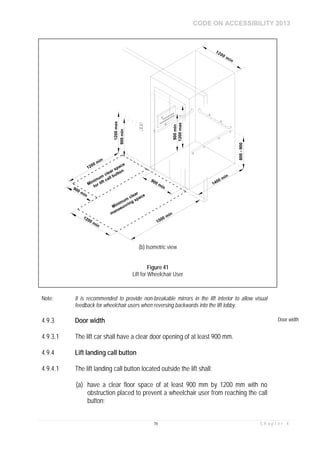


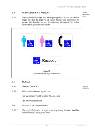


![Attack surfaces and attack tress[inform]](https://cdn.slidesharecdn.com/ss_thumbnails/lecture03-260108015941-a4dee53b-thumbnail.jpg?width=640&height=640&fit=bounds)

