Download to read offline
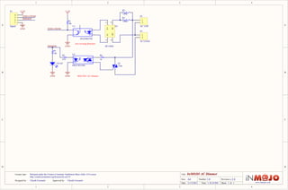

1. This document is a circuit diagram for an AC dimmer that uses a triac and MOC3021 optocoupler to control the amount of power delivered to a load from an AC power source. 2. The circuit uses a 4N25SR2VM optocoupler to detect zero crossings in the AC waveform and send signals to a MOC3021 optocoupler which triggers the triac and controls the phase angle of the AC waveform to adjust the load voltage. 3. Resistors R1-R3 set the trigger level of the optocouplers while R4-R6 provide isolation between the AC and control sides of the circuit.


![Ba115 schematic[1]](https://cdn.slidesharecdn.com/ss_thumbnails/ba115schematic1-140615001731-phpapp01-thumbnail.jpg?width=640&height=640&fit=bounds)