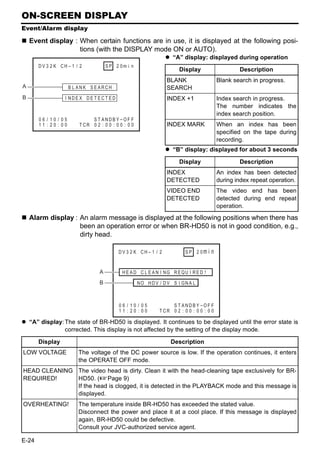
Download to read offline

![Supplement
This equipment is in conformity with the provisions and protection requirements of the corresponding
European Directives. This equipment is designed for professional video appliances and can be used in
the following environments:
Residential (including both of the location type class 1 and 2 found in IEC 1000-2-5)
Commercial and light industrial (including, for example, theatres)
Urban outdoors (based on the definition of location type class 6 in IEC 1000-2-5)
In order to keep the best performance and furthermore for electromagnetic compatibility we recom-
mend to use cables not exceeding the following lengths:
Port Cable Length
AUDIO SHIELDED CABLE 10 meters
LINE COAXIAL CABLE 10 meters
COMPONENT COAXIAL CABLE 10 meters
Y/C COAXIAL CABLE 10 meters
IEEE1394 SHIELDED TWIST PAIR CABLE 4.5 meters
HDMI SHIELDED TWIST PAIR CABLE 5 meters
REMOTE SHIELDED TWIST PAIR CABLE 5 meters
The inrush current of this apparatus is 9.0 amperes.
Caution:
Where there are strong electromagnetic waves or magnetism, for example near a radio or TV trans-
mitter, transformer, motor, etc., the picture and sound may be disturbed. In such a case, please keep
the apparatus away from the sources of the disturbance.
Information for Users on Disposal of Old Equipment
[European Union]
This symbol indicates that the electrical and electronic equipment should not be dis-
posed as general household waste at its end-of-life. Instead, the product should be
handed over to the applicable collection point for the recycling of electrical and elec-
tronic equipment for proper treatment, recovery and recycling in accordance with
your national legislation.
By disposing of this product correctly, you will help to conserve natural resources and
will help prevent potential negative effects on the environment and human health
which could otherwise be caused by inappropriate waste handling of this product.
Attention: For more information about collection point and recycling of this product, please con-
This symbol is tact your local municipal office, your household waste disposal service or the shop
only valid in where you purchased the product.
the European Penalties may be applicable for incorrect disposal of this waste, in accordance with
Union. national legislation.
(Business users)
If you wish to dispose of this product, please visit our web page www.jvc-europe.com
to obtain information about the take-back of the product.
[Other Countries outside the European Union]
If you wish to dispose of this product, please do so in accordance with applicable
national legislation or other rules in your country for the treatment of old electrical
and electronic equipment.
III](https://image.slidesharecdn.com/br-hd50brochure-110419040454-phpapp01/85/JVC-BR-HD50-4-320.jpg)
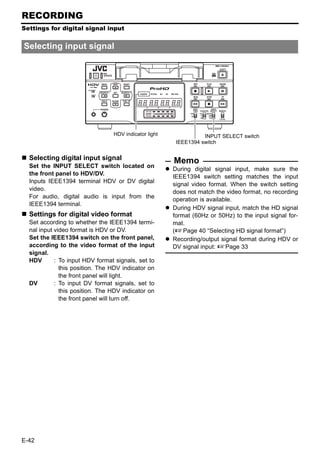
![INTRODUCTION
HDV and DV format
This unit records in HDV or DV format.
DV format is a standard for recording SD (Standard-Definition) video onto DV cassettes or mini DV cas-
settes.
HDV format is a standard for recording HD (High-Definition) video onto DV cassettes or mini DV cas-
settes.
The two HDV recording formats are HDV 720p and HDV 1080i.
HDV 720p : 720p (720 effective scanlines, progressive scan)
HDV 1080i : 1080i (1080 effective scanlines, interlace scan)
This unit supports the HDV 720p format.
HDV 60 or 50
[IEEE1394] switch
HDV and DV signal input/output
HDV signals and DV signals are input/output from the IEEE1394 terminal.
HDV signals from the IEEE1394 terminal are recorded in HDV format.
DV signals from the IEEE1394 terminal are recorded in DV format.
Recorded HDV signals or DV signals are output from the IEEE1394 terminal during playback.
Digital audio is also input/output from the IEEE1394 terminal, together with HDV signals or DV signals.
The front panel IEEE1394 switch must be set on the front panel, according to whether the input/output
signal from the IEEE1394 terminal is in HDV format or DV format.
When the input signal or playback signal is in HDV format, the front panel HDV display is lit.
Analog signal input is digitally converted and recorded in DV format.
HD signal format
This unit is compatible with both 60Hz and 50Hz HD signal formats. The HDV signal format must be set
on this unit, according to whether the input/playback HD signal format is 60Hz or 50Hz.
(Set this using 60/50 SEL in the SYSTEM [2/2] Menu screen.)
Menu settings on this unit can be checked by whether the front panel 60 or 50 indicator light is lit.
The field frequency for DV signals and analog signals is fixed by region.
[U model: 60Hz (NTSC), E model: 50Hz (PAL)]
E-6](https://image.slidesharecdn.com/br-hd50brochure-110419040454-phpapp01/85/JVC-BR-HD50-10-320.jpg)
![HDV (720p) and DV format
HDV 720p format DV format
Video signal *1 60Hz:720/30p, 720/24p, 480/60p U (NTSC) : 480/60i
50Hz:720/25p, 576/50p E (PAL) : 576/50i
Pixel count 1280 × 720 U (NTSC) : 720 × 480
720 × 480 (480/60p)
E (PAL) : 720 × 576
720 × 576 (576/50p)
Aspect ratio 16:9 4:3 (16:9)
Video compression MPEG-2 Video (Profile & level: MP@H-14) DV
format
Bit rate after About 19 Mbps About 25 Mbps
compression
Audio compression MPEG1 Audio Layer II Linear PCM
format
Audio channels 2CH (48 kHz,16 bit) 2CH (48 kHz,16 bit)
4CH (32 kHz,12 bit) *2
*1 : For HDV/DV signals, the unit records the same signals as the input signals.
*2 : During analog audio input, only CH1/CH2 are recorded.
Viewing video signal display (Example)
720/30p: 720 effective scanlines, 30-frame progressive scan
480/60i: 480 effective scanlines, 60-field interlace scan
Recording time
The recording/playback speed for HDV format is SP mode only.
Though DV format recording and playback speed has SP and LP modes, this unit supports SP mode
only.
The cassette recording time is the same for HDV and DV format.
Standard DV Mini DV cassettes Recording time
Recording time
cassettes
M-DV63PRO About 63 minutes
LA-DV276 About 276 minutes
M-DV63HD About 63 minutes
LA-DV186 About 186 minutes
LA-DV124 About 124 minutes
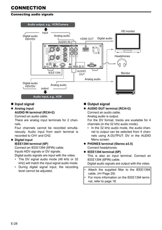
HD video output
HD video is output from the HDMI OUT terminal and the COMPONENT OUT terminal.
HDMI OUT terminal : Outputs HD/SD digital video and digital audio.
This is connected to a monitor with an HDMI terminal.
(HDMI : High Definition Multimedia Interface)
COMPONENT OUT terminal: Outputs HD/SD analog video. Does not output audio.
This is connected to an HD-compatible monitor with COMPONENT input
terminal.
The video format to output from the HDMI OUT terminal and the COMPONENT OUT terminal can be
selected using OUT FORMAT [60]/OUT FORMAT [50] in the VIDEO Menu screen.
E-7](https://image.slidesharecdn.com/br-hd50brochure-110419040454-phpapp01/85/JVC-BR-HD50-11-320.jpg)
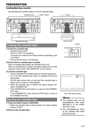
![NAMES AND FUNCTIONS OF PARTS
Front panel
2 1
3
4
1Cassette loading slot/LED 3[EJECT] button
• For loading a cassette into or unloading it • Press this button to eject the cassette.
from the slot.
Insert a standard DV cassette or a mini DV
Memo
It takes about 6 seconds for the cassette to be
cassette. (XPage 37)
ejected.
• When BR-HD50 is in the OPERATE OFF
The cassette can be ejected even when BR-
state and a cassette is loaded, it changes to
HD50 is in the OPERATE OFF mode. After the
the OPERATE ON state.
eject action is completed, BR-HD50 returns to
• With a cassette loaded, the LED lights up in
the OPERATE OFF mode.
green.
When a cassette is being loaded or ejected,
the LED flashes. 4Operation buttons
2[OPERATE] button/LED [REC] button/LED
• Press this button to turn on the power and BR- • Hold down this button and press the PLAY
HD50 becomes ready for operation. button to start recording. During recording,
(OPERATE ON) the red LED lights up.
Press this button again when BR-HD50 is • Hold down this button and press the
already on to turn off the power. (OPERATE OFF) PAUSE button to pause recording.
• OPERATE LED lights up as follows. • If this button is pressed during recording, an
OPERATE ON : the green LED lights up index signal is recorded on the tape (when
OPERATE OFF : the red LED lights up INDEX WRITE in the SYSTEM [2/2] Menu
VCR error : the red LED blinks screen is set to ON).
• When this button is pressed in the STOP
Memo mode, the time code generator value can
If DC IN MODE in the SYSTEM [2/2] Menu be checked while the button is being held
screen is set to “OPE ON”, and power is sup- down. If TC DUPLI.: DV Menu is set to
plied to the DC IN terminal on the rear panel, AUTO, the time code, date and time of the
power is turned on and the unit enters OPER- IEEE1394 terminal can be checked. (In DV
ATE ON mode without pressing this button. mode only)
Even after the power is turned off with this but-
ton, BR-HD50 is live with a small amount of
electricity.
Therefore, if BR-HD50 is not to be used for a
long period of time, please remove the AC
adapter to save energy.
E-10](https://image.slidesharecdn.com/br-hd50brochure-110419040454-phpapp01/85/JVC-BR-HD50-14-320.jpg)
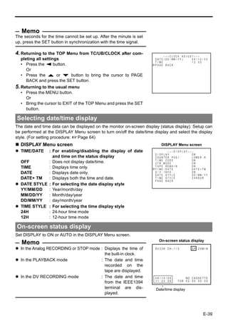
![[PLAY] button/LED [STOP] button/LED
• Press this button to start playing back a • Press this button to stop operation.
tape. During playback, the green LED lights • When BR-HD50 is in the STANDBY-OFF
up. mode, press this button to enter the
• When recording is paused, press this but- STANDBY-ON mode.
ton to resume recording. • While stopped, the LED lights green.
[PAUSE] button/LED Memo
• During recording, press this button to pause There are two stop modes.
it. STANDBY-OFF: For protecting the tape and
• In the PLAYBACK or STOP mode, press the drum, the drum does not rotate.
this button to enter the STILL mode. In the STANDBY-ON: The drum rotates so that it
RECORDING PAUSE or STILL mode, the starts up faster after BR-HD50 moves into
green LED lights up. another mode.
• When BR-HD50 is in the STILL mode,
press this button for frame advance play- [REW] button/LED
back. (In DV mode only)
• When BR-HD50 enters the STOP mode,
Memo press this button to rewind the tape.
Still images or images in frame advance can be • When BR-HD50 is in the PLAYBACK or
selected with STL/F.ADV: DV of the SYSTEM [1/ STILL mode, press this button for reverse
2] Menu screen. playback. The rewind playback speed can
be changed by pressing the SEARCH+/S
[FF] button/LED button h or the SEARCH–/Q button
• When BR-HD50 enters the STOP mode, (when “Q, S” KEY FUNC. in the SYS-
press this button to fast-forward the tape. TEM [1/2] Menu screen is set to VAR/
• When BR-HD50 is in the PLAYBACK or RECV).
STILL mode, press this button for fast-for- (XPage 53 “Slow playback and Search
ward playback. The fast forward playback mode”)
speed can be changed by pressing the • During rewinding or rewind playback, the
SEARCH+/S button h or the SEARCH–/ LED lights up in green.
Q button (when “Q, S” KEY FUNC. in
the SYSTEM [1/2] Menu screen is set to
VAR/RECV).
(XPage 53 “Slow playback and Search
mode”)
• During fast-forwarding or fast-forward play-
back, the LED lights up in green.
E-11](https://image.slidesharecdn.com/br-hd50brochure-110419040454-phpapp01/85/JVC-BR-HD50-15-320.jpg)
![NAMES AND FUNCTIONS OF PARTS
Front panel (continued)
a
b c 9 0 8 7 6 5
5[REMOTE/LOCAL] switch 6[INPUT SELECT] switch
This switch is used to select how BR-HD50 is This switch is used to select input signals.
to be operated. HDV/DV : Inputs IEEE1394 terminal HDV sig-
LOCAL : Use this setting if BR-HD50 is to nals or DV signals.
be controlled with the key opera- The 8 IEEE1394 switch needs to
tion of the unit. be set, according to whether the
REMOTE : Use this setting to control this unit video format is HDV or DV.
using the REMOTE terminal, LINE : For inputting the composite images
SERIAL REMOTE terminal, or of the LINE IN terminal and analog
IEEE1394 terminal. audio signals.
Y/C : For inputting the Y/C separate
Memo video signal of the Y/C IN terminal
Select to enable/disable operation with the
and analog audio signals.
REMOTE terminal, using REMOTE SEL 9P on
the REMOTE [1/2] Menu screen. Note
To control BR-HD50 with the SERIAL Switching is invalid during recording.
REMOTE terminal or IEEE1394 terminal, this Switching this switch during playback may
switch setting can be set up with REMOTE briefly cut off the audio.
SEL SERIAL or REM SEL HDV/DV in the
REMOTE [1/2] Menu screen. (XPage 70) 7[COUNTER] switch
If it is set to REMOTE, the buttons that can be Switches the displayed information on the 9
operated from the unit are selectable from counter display and the monitor counter dis-
LOCAL FUNCTION in the REMOTE [1/2] play.
Menu screen. CTL : It displays the counter in hour, minute,
second and frame based on CTL (con-
trol signal).
TC : It displays the time code data.
UB : It displays the user’s bit (UB).
E-12](https://image.slidesharecdn.com/br-hd50brochure-110419040454-phpapp01/85/JVC-BR-HD50-16-320.jpg)
![8[IEEE1394] IEEE1394 terminal switch [DVCAM] indicator light
Set this switch according to the video format of Lights when playing a tape recorded in
the IEEE1394 input signal and playback sig- DVCAM format.
nal. When the video format is HDV, a HDV Only tapes recorded in SP mode can be
indicator is lit. played.
HDV : Use this setting when the video [60] indicator light
format is HDV (HDV indicator is Lights when 60/50 SEL in the SYSTEM [2/2]
lit).
Menu screen is set to 60.
DV : Use this setting when the video The HD signal format on this unit is set to
format is DV (HDV indicator is off). 60Hz.
Note [50] indicator light
Video and audio recording and playback using Lights when 60/50 SEL in the SYSTEM [2/2]
the IEEE1394 terminal are unavailable when Menu screen is set to 50.
the switch setting differs from the video format. The HD signal format on this unit is set to
When the IEEE1394 terminal is used to input/ 50Hz.
output video or audio signals with a non-linear
editing system, and the format is changed by Memo
The field frequency for DV signals and analog
switching this switch, either reconnect the
signals are fixed by region.
IEEE1394 cable, or use the OPERATE button
(U model: 60Hz, E model: 50Hz)
to reset the power.
9Counter display [REC INH] indicator light
Lights upon loading a cassette that cannot be
Displays the counter, menu settings, and oper-
recorded.
ation mode. (8 digits)
• Counter display b[PHONES] terminal
The displayed contents can be selected This is the mini jack terminal for connecting to
using the 7 COUNTER switch. the headphone. (Stereo ø3.5)
• For menu settings, menu code numbers are • When playing back tapes recorded in 32
displayed. kHz mode, the audio channel output from
0Audio level indicator this terminal is selected using A.OUTPUT:
Displays the audio level for CH-1/3 and CH-2/ DV on the AUDIO Menu screen.
4. c[PHONES] Headphone volume
In RECORDING mode, audio recording level Use this switch to adjust the output level of the
is displayed. In PLAY mode, audio playback PHONES terminal.
level is displayed. Both channels are adjusted at the same time.
Only the audio recording level during analog
input can be adjusted.
aIndicator lights
[HDV] indicator light
Lights when the video format for the IEEE1394
terminal input signal or playback signal is HDV.
When this indicator is lit, set the 8 IEEE1394
switch to HDV.
When this indicator is off, set the 8 IEEE1394
switch to DV.
E-13](https://image.slidesharecdn.com/br-hd50brochure-110419040454-phpapp01/85/JVC-BR-HD50-17-320.jpg)
![NAMES AND FUNCTIONS OF PARTS
Front panel (continued)
e f
d h g
d[HOLD] button g[CUE UP] button
Pressing this button while stopped will engage When the 7 COUNTER switch is set to TC,
the time code and user’s bit PRESET mode. press this button to display the Multi Cue-up
(When TCG SELECT in the TC/UB/CLOCK [1/ screen on the monitor.
2] Menu screen is set to PRESET) When the Multi-Cue-up screen is displayed,
In time code PRESET mode, press this button press this button to start searching the
to return to the normal display. selected tape position.
(XPage 59 “Presetting the time code”) (XPage 56 “Multi cue-up”)
e[MENU] button hSpecial functions/Setting buttons
If this button is pressed in the STOP/STILL The following buttons have different functions
mode or when no cassette is loaded, the menu depending on whether the normal screen or
is displayed on the monitor connected to the the setting screen is displayed.
video output terminal (LINE OUT, Y/C OUT, Setting screens:
COMPONENT OUT, or HDMI OUT terminal). Menu, Date/Time setting, Time code preset
The counter display shows menu code num- and Multi Cue-up
bers. [DISP/R] button
When the menu is displayed, press this button
• Press this button during PLAY mode to dis-
to return to the normal display. play the video output format on the counter
(XPage 64 “Setting the menus”) display.
f[RESET] button • During the STOP or REC mode, the audio
• To reset the CTL counter display to “00”, recording level is increased. (Pressing simul-
press this button. taneously with Q or S button) (When “Q,
• If this button is pressed when the time code S” KEY FUNC. in the SYSTEM [1/2] Menu
preset screen is displayed, all the digits of screen is set to VAR/RECV)
the time code or the user’s bit are reset to (XPage 44 “Adjusting audio recording
“00”. level”)
• When the Multi Cue-up screen is displayed, • When the setting screen is displayed, this
press this button to clear the registered cue- button is used to select the items or setting.
up points.
E-14](https://image.slidesharecdn.com/br-hd50brochure-110419040454-phpapp01/85/JVC-BR-HD50-18-320.jpg)
![[BLANK/P] button [SEARCH–/Q] button
• When BR-HD50 is in the STOP mode, • During normal display, the function of this
press this button to start blank search. It button can be selected using “Q, S” KEY
searches the unrecorded part of the tape FUNC. in the SYSTEM [1/2] Menu screen.
and goes into the still mode. If it is set to VAR/RECV, the searching
(XPage 54 “Blank search”) speed decreases if this button is pressed
• During the STOP or REC mode, the audio during a search operation.
recording level is decreased. (Pressing simul- (XPage 53 “Slow playback and Search
taneously with Q or S button) (When “Q, mode”)
S” KEY FUNC. in the SYSTEM [1/2] Menu If it is set to INDEX, press this button to
screen is set to VAR/RECV) start reverse index search. This function is
(XPage 44 “Adjusting audio recording not effective during recording or recording
level”) pause.
• When the setting screen is displayed, this (XPage 54 “Index search”)
button is used to select the items or setting. • During the STOP or REC mode, CH1 is
[SEARCH+/S] button selected as the channel for adjusting the
audio recording level. (When “Q, S” KEY
• During normal display, the function of this
button can be selected using “Q, S” KEY FUNC. in the SYSTEM [1/2] Menu screen is
FUNC. in the SYSTEM [1/2] Menu screen. set to VAR/RECV)
(XPage 44 “Adjusting audio recording
If it is set to VAR/RECV, the searching
speed increases if this button is pressed level”)
during a search operation. • When the setting screen is displayed, this
button is used to return to the previous
(XPage 53 “Slow playback and Search
mode”) menu or select setting digits.
If it is set to INDEX, press this button to [SET] button
start forward index search. This function is • When the Menu screen, Date/Time setting
not effective during recording or recording screen or the Multi Cue-up screen is dis-
pause. played, press this button to confirm the set-
(XPage 54 “Index search”) ting.
• During the STOP or REC mode, CH2 is • In time code PRESET mode, press this but-
selected as the channel for adjusting the ton to preset the set time codes or user’s bit
audio recording level. (When “Q, S” KEY to the time code generator.
FUNC. in the SYSTEM [1/2] Menu screen is
set to VAR/RECV)
(XPage 44 “Adjusting audio recording
level”)
• When the setting screen is displayed, this
button is used to select items or setting dig-
its.
E-15](https://image.slidesharecdn.com/br-hd50brochure-110419040454-phpapp01/85/JVC-BR-HD50-19-320.jpg)
![NAMES AND FUNCTIONS OF PARTS
Rear panel
2 1 6 7
4
3 5 8 9 0
1[VIDEO LINE IN] terminal (BNC) 4[VIDEO Y/C OUT] terminal (4-PIN)
This is the input terminal for composite video This is the output terminal for Y/C separate
signals. video signals.
• To input video via this terminal, set the • It displays the Menu setting screen, Date/
INPUT SELECT switch located on the front Time setting screen and warning informa-
panel to “LINE”. tion.
2[VIDEO Y/C IN] terminal (4-PIN) • If DISPLAY in the DISPLAY Menu screen is
This is the input terminal for Y/C separate set to “ON” or “AUTO”, information will be
video signals. displayed on-screen, e.g., the operation
mode, date/time and counter. (XPage 20)
• To input video via this terminal, set the
INPUT SELECT switch located on the front • When the input signal or playback signal is
panel to “Y/C”. in HDV format, this terminal outputs video
that is converted down to 480i or 576i.
• When wide-screen ID signals are input, the
wide-screen ID signal is recorded. Select the style for displaying down-con-
verted video on a monitor screen with a 4:3
3[VIDEO LINE OUT] terminal (BNC) aspect ratio, using DOWN CONV. MODE
This is the output terminal for composite video on the VIDEO Menu screen. (XPage 74)
signals. • When tapes that have recorded wide-
• It displays the Menu setting screen, Date/ screen signals are played back, the wide-
Time setting screen and warning informa- screen ID signal is output.
tion. When playing back an HDV recorded tape,
• If DISPLAY in the DISPLAY Menu screen is wide-screen ID signals are output according
set to “ON” or “AUTO”, information will be to the mode set using DOWN CONV.
displayed on-screen, e.g., the operation MODE in the VIDEO Menu screen.
mode, date/time and counter. (XPage 20)
• When the input signal or playback signal is Memo
Whether or not to enable SET UP for analog sig-
in HDV format, this terminal outputs video
nals (composite, Y/C separate and component
that is converted down to 480i or 576i.
signals) can be selected with SET UP [60]: DV in
Select the style for displaying down-con-
the VIDEO Menu screen (for U model only).
verted video on a monitor screen with a 4:3
aspect ratio, using DOWN CONV. MODE
on the VIDEO Menu screen. (XPage 74)
E-16](https://image.slidesharecdn.com/br-hd50brochure-110419040454-phpapp01/85/JVC-BR-HD50-20-320.jpg)
![5[COMPONENT OUT] Component sig- 9[CH2/4 AUDIO OUT] terminal (RCA)
nal output terminal (BNC×3) Use this terminal to output analog audio sig-
Output terminal for component video signals nals.
(Y/PB/PR). Outputs analog HD/SD video. Con- • In the 48 kHz audio mode, it outputs the
nect this to an HD-compatible monitor with a sound of CH2.
COMPONENT IN terminal. • The output audio channel during playback
• The video format to output from this termi- of tapes recorded in 32 kHz audio mode, or
nal can be selected using OUT FORMAT the EE audio channel during DV signal
[60]/[50] in the VIDEO Menu screen. input in 32 kHz audio mode, can be
(XPage 73, 74) selected using A.OUTPUT: DV in the
• It displays the Menu setting screen, Date/ AUDIO Menu screen. (XPage 72)
Time setting screen and warning informa- 0[HDMI OUT] HDMI signal output termi-
tion. nal
• If DISPLAY in the DISPLAY Menu screen is Outputs HDMI signals. (HDMI : High Definition
set to “ON” or “AUTO”, information will be Multimedia Interface)
displayed on-screen, e.g., the operation
Outputs digital HD/SD video and digital audio.
mode, date/time and counter. (XPage 20) This is connected to a monitor with an HDMI
6[CH1 AUDIO IN] terminal (RCA) terminal.
Use this terminal to input analog audio signals. • The video format to output from this termi-
To enable audio input via this terminal, set the nal can be selected using OUT FORMAT
INPUT SELECT switch located on the front [60]/[50] and MONITOR SELECT in the
panel to “LINE” or “Y/C”. VIDEO Menu screen. (XPage 73, 74)
Analog signals are recorded on CH1. • It displays the Menu setting screen, Date/
7[CH2 AUDIO IN] terminal (RCA) Time setting screen and warning informa-
Use this terminal to input analog audio signals. tion.
To enable audio input via this terminal, set the • If DISPLAY in the DISPLAY Menu screen is
set to “ON” or “AUTO”, information will be
INPUT SELECT switch located on the front
panel to “LINE” or “Y/C”. displayed on-screen, e.g., the operation
mode, date/time and counter. (XPage 20)
Analog signals are recorded on CH2.
8[CH1/3 AUDIO OUT] terminal (RCA) Memo
Use this terminal to output analog audio sig- Video is not displayed when the connected
nals. monitor does not support the video format
• In the 48 kHz audio mode, it outputs the selected using OUT FORMAT [60]/[50] in the
sound of CH1. VIDEO Menu screen.
• The output audio channel during playback If this occurs, set MONITOR SELECT to
of tapes recorded in 32 kHz audio mode, or HDMI[A].
the EE audio channel during DV signal If the monitor has a DVI-D terminal that sup-
input in 32 kHz audio mode, can be ports HDCP, you can watch digital video by
selected using A.OUTPUT: DV in the connecting an HDMI↔DVI-D cable.
AUDIO Menu screen. (XPage 72) When the video format of the IEEE1394 input
signal differs from the IEEE1394 switch, or
INPUT SELECT switch is set to HDV/DV and a
signal is not input into the IEEE1394 terminal,
no signal is output from the HDMI OUT termi-
nal. ("no 1394" is displayed on the counter dis-
play.) Similarly, no signal is output from the
HDMI OUT terminal when a blank cassette
tape is played. ("-------" is displayed on the
counter display.)
E-17](https://image.slidesharecdn.com/br-hd50brochure-110419040454-phpapp01/85/JVC-BR-HD50-21-320.jpg)
![NAMES AND FUNCTIONS OF PARTS
Rear panel (continued)
g
d
c b a e h f
a[IEEE1394] IEEE1394 terminal (6P) • To record a time code via this terminal, set
This is the input/output terminal for IEEE1394- TC DUPLI.: DV in the TC/UB/CLOCK [1/2]
compliant digital signals. Menu screen to AUTO or NONDROP. (In
Inputs HDV signals or DV signals when DV mode only)
recording. Digital audio is input simulta- • To control this unit via this terminal, set
neously. REM SEL HDV/DV in the REMOTE [1/2]
During playback, it outputs HDV signals, DV Menu screen to ON or LOC/REM.
signals, and digital audio on the playback tape. Note
Upon analog signal input, EE images and EE If HDV/DV signals are not input/output when the
audio are output. EE images are DV format IEEE1394 cable is connected, check whether the
signals (480i or 576i) (Only when IEEE1394 signal format matches the IEEE1394 switch set-
switch is set to DV). ting on the front panel. If the settings match,
• This unit records and plays 720p format either reconnect the IEEE1394 cable, or reset the
HDV signals. power to the unit.
720p HDV signals and DV signals from this
terminal are recorded as is, without format
bDC power input terminal
conversion.
This terminal is for inputting DC 12 V. Connect
• To enable signal input via this terminal, set
the DC power cord of the supplied AC adapter.
the INPUT SELECT switch located on the
front panel to “HDV/DV”. Memo
• The IEEE1394 switch located on the front When power is supplied to this terminal, the
panel must be set to “HDV” or “DV”, accord- OPERATE indicator located on the front panel
ing to the input signal to this terminal or the lights up. (The indicator turns red when BR-
video format of the playback tape. HD50 is in the OPERATE OFF state)
• The audio mode (48 kHz or 32 kHz) cannot Whether to set BR-HD50 to enter the OPER-
be changed for the input audio signal via ATE ON mode or OPERATE OFF mode when
this terminal. It will be recorded using the power is supplied to the terminal can be
input signal audio mode. 4-channel record- selected with DC IN MODE in the SYSTEM [2/
ing is possible in the 32 kHz audio mode. 2] Menu screen.
• Power cannot be supplied via this terminal.
cDC power cord clamp
Use this clamp to fasten the DC power cord.
d[SIGNAL GND] terminal
This is the grounding terminal for signals.
E-18](https://image.slidesharecdn.com/br-hd50brochure-110419040454-phpapp01/85/JVC-BR-HD50-22-320.jpg)
![e[SERIAL REMOTE] terminal (mini jack)
This terminal is for connecting to the serial
remote controller.
To operate BR-HD50 with this terminal, per-
form the following settings.
• Set REMOTE SEL SER in the REMOTE [1/
2] Menu screen to “ON” or “LOC+REM”.
ON : When the 5 REMOTE/LOCAL
switch on the front panel is set to
“REMOTE”, this terminal becomes
effective.
LOC+REM : This terminal is effective regard-
less of the setting of the 5
REMOTE/LOCAL switch on the
front panel.
Memo
To use this terminal as the foot switch input, set
FOOT SW in the REMOTE [2/2] Menu screen.
(XPage 71)
f[REMOTE] RS-422A terminal
(D-SUB 9P)
This terminal is for connecting to an RS-422A
serial interface-compatible editing remote con-
troller (e.g. RM-G820).
With this terminal, BR-HD50 can be used as a
player of an editing system.
To operate BR-HD50 with RS-422A, perform
the following settings.
• Set REMOTE SEL 9P in the REMOTE [1/2]
Menu screen to “ON”.
• Set the 5 REMOTE/LOCAL switch on the
front panel to “REMOTE”.
Memo
Screws for securing connectors differ by region.
U model : inch screws
E model : metric screws
gFan
This is a ventilation port for the fan motor.
Do not place objects in this area.
hSlot cover for servicing
This is used for servicing the unit.
E-19](https://image.slidesharecdn.com/br-hd50brochure-110419040454-phpapp01/85/JVC-BR-HD50-23-320.jpg)
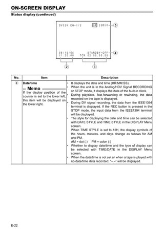
![“B” display: Messages for incorrect operation are displayed for about 3 seconds.
They are displayed when the DISPLAY mode is ON or AUTO.
Display Description
INVALID TAPE! Data tape for PCs or DVC PRO tape is used.
The cassette tape will be automatically ejected.
LP TAPE! The user attempted to play back a tape recorded in the LP mode.
BR-HD50 cannot record or play in the LP mode.
NO HDV/DV SIG- The user attempted to record without HDV or DV signal input.
NAL
COPY INHIBIT The user attempted to record copy-guarded signals.
REC INHIBIT The user attempted to record on a tape that is not ready for recording (the rear
switch is set to SAVE).
OPERATION This message is displayed when an operation button is pressed with OPERA-
LOCK TION LOCK enabled. To enable OPERATION LOCK, set OPERATION LOCK in
the SYSTEM [2/2] Menu screen to ON.
PB INHIBIT This message is displayed when the HD/SD signal format setting differs during
[60/50] playback of a tape recorded in HDV/DV format.
REC INHIBIT • (for U model)
[60/50] This message is displayed when the unit is recorded in PAL mode.
• (for E model)
This message is displayed when the unit is recorded in NTSC mode.
50/25 INHIBIT • When 60/50 SEL in the SYSTEM [2/2] Menu screen is set to 60, this message
is displayed when HDV signal format is not 60Hz.
• This message is displayed when the DV signal from the IEEE1394 terminal is
not NTSC.
60/30 INHIBIT • When 60/50 SEL in the SYSTEM [2/2] Menu screen is set to 50, this message
is displayed when HDV signal format is not 50Hz.
• This message is displayed when the DV signal from the IEEE1394 terminal is
not PAL.
E-25](https://image.slidesharecdn.com/br-hd50brochure-110419040454-phpapp01/85/JVC-BR-HD50-29-320.jpg)
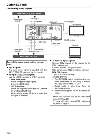
![CONNECTION
Connecting with SERIAL REMOTE terminals
The following describes examples of SERIAL REMOTE terminal connection.
To use the SERIAL REMOTE terminals, set REMOTE SEL SER of the REMOTE [1/2] Menu screen
to “ON” or “LOC+REM.” (XPage 70)
Operate BR-HD50 with the wired remote controller
Connect the wired remote controller to the
SERIAL REMOTE terminal.
SERIAL
REMOTE
Wired remote
controller
Start/stop recording with an external switch, e.g., a foot switch.
Connect an external switch, e.g., a foot switch,
to the SERIAL REMOTE terminal.
The format of the input signals can be selected
with FOOT SW in the REMOTE [2/2] Menu
screen. (XPage 71)
SERIAL
REMOTE
Foot
switch
E-30](https://image.slidesharecdn.com/br-hd50brochure-110419040454-phpapp01/85/JVC-BR-HD50-34-320.jpg)
![CONNECTION
Connecting the AC adapter
Connect the supplied AC adapter to BR-HD50.
1. Clamp
Screw
3. Clamp
Supplied AC adapter
DC IN terminal
4.
Supplied power cord
DC cord 2.
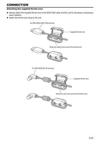
Supplied ferrite core 5.
OPERATE indicator Always attach the supplied ferrite core
to the DC cord. (XPage 29)
OPERATE
1. Remove one screw on the back panel of the
button unit, and remove the DC cord clamp.
2. Connect the DC cord of the AC adapter to
the DC IN terminal of BR-HD50.
3. To prevent accidental disconnection of the
DC cord, insert the DC cord into the clamp,
orient the clamp as shown in the figure
above, and secure the clamp to the unit.
Memo Use the screw removed in step 1 above to
Even in the OPERATE OFF mode, a small secure the clamp to the unit.
amount of electricity will still flow into the unit. 4. Connect the supplied power cord to the AC
When the unit is in the OPERATE OFF mode, IN terminal of the AC adapter.
no operation can be performed except that of 5. Connect the power cord to the power out-
the OPERATE buttons and cassette loading/ let.
ejecting. • BR-HD50 is turned on and the OPERATE
indicator lights up in red.
(OPERATE OFF mode)
• If DC IN MODE of the SYSTEM [2/2] Menu
screen is set to “OPE ON”, the OPERATE
indicator will light up in green.
(OPERATE ON mode)
Note
Supply power to BR-HD50 using the supplied AC adapter. Do not
use other power sources.
Do not unplug the DC cord and/or the power cord during recording
or playback. LOW VOLTAGE
If the supply voltage is low, an alarm display of “LOW VOLTAGE”
is shown.
Alarm message
E-31](https://image.slidesharecdn.com/br-hd50brochure-110419040454-phpapp01/85/JVC-BR-HD50-35-320.jpg)
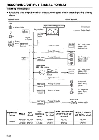
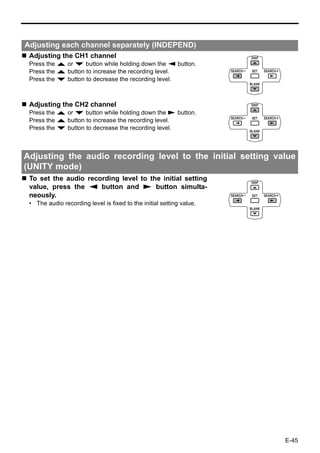
![RECORDING/OUTPUT SIGNAL FORMAT
Inputting digital signal
Recording and output terminal video/audio signal format when inputting digital signal
Input terminal Output terminal
Video signals
Front panel Tape : HDV (720p, 480p, 576p)
IEEE1394 switch DV (480i, 576i) recording Audio signals
Digital
IEEE1394 video HDV format Digital video
DV format
Digital audio
Digital audio
MONITOR SELECT
Digital EE (HDMI[A]/OUT FRMT)
video HDMI OUT HD/SD Digital video
(480i, 480p, 720p, 1080i)
Digital EE
(576i, 576p, 720p, 1080i)
audio MENU: Digital audio
OUT FORMAT[60]
OUT FORMAT[50] COMPONENT
OUT
Cross converter
(480I, 480P, 720P, 1080I) Y
(576I, 576P, 720P, 1080I) HD/SD Analog compo-
D/A con-
PB
nent video
version
(480i, 480p, 720p, 1080i)
(576i, 576p, 720p, 1080i)
PR
Digital EE audio
Down converter
LINE Composite
OUT video (480i)
D/A con- Analog EE video
version (576i)
Y/C
OUT Y/C separate
D/A con- Analog EE video video (480i)
version (576i)
AUDIO OUT
D/A con- Analog EE audio CH 1/3 CH 2/4
version Analog audio
Input video HD signal Input Tape record- HDMI OUT terminal LINE OUT terminal
format format (*1) signal ing format COMPONENT OUT terminal (*2) Y/C OUT terminal
720/30p 720/30p
720/60p, 480/60p, 1080/60i,
60Hz 720/24p 720/24p 480/60i
480/60i
HDV 480/60p 480/60p
720/25p 720/25p 720/50p, 576/50p, 1080/50i,
50Hz 576/50i
576/50p 576/50p 576/50i
Input video Input Tape record- HDMI OUT terminal LINE OUT terminal
Model
format signal ing format COMPONENT OUT terminal (*2) Y/C OUT terminal
720/60p, 480/60p, 1080/60i,
U model 480/60i 480/60i 480/60i
480/60i
DV
720/50p, 576/50p, 1080/50i,
E model 576/50i 576/50i 576/50i
576/50i
*1 : Set using 60/50 SEL in the SYSTEM [2/2] Menu screen.
*2 : Set using OUT FORMAT [60]/OUT FORMAT [50] in the VIDEO Menu screen.
E-33](https://image.slidesharecdn.com/br-hd50brochure-110419040454-phpapp01/85/JVC-BR-HD50-37-320.jpg)
![RECORDING/OUTPUT SIGNAL FORMAT
Playback
Output terminal video/audio signal format during playback
Output terminal
Tape : HDV (720p, 480p, 576p)/
DV (480i, 576i)/DVCAM (480i, 576i) Video signals
format
Audio signals
Playback MONITOR SELECT
(HDMI[A]/OUT FRMT)
Digital Digital video HDMI OUT HD/SD Digital video
audio (480i, 480p, 720p, 1080i)
(576i, 576p, 720p, 1080i)
MENU:
Digital audio
OUT FORMAT[60]
OUT FORMAT[50] COMPONENT
Cross converter OUT
(480I, 480P, 720P, 1080I) Y
(576I, 576P, 720P, 1080I) D/A con- HD/SD Analog compo-
version PB nent video
Digital audio (480i, 480p, 720p, 1080i)
(576i, 576p, 720p, 1080i)
PR
HDV format IEEE1394
Digital video HDV (720p, 480p, 576p)
/DV (480i, 576i) Digital
DV format video
Digital audio Digital audio
Down converter
LINE Composite
OUT video (480i)
D/A con- Analog video
(576i)
version
Y/C
OUT Y/C separate
D/A con- Analog video video (480i)
version (576i)
AUDIO OUT
D/A con- Analog audio CH 1/3 CH 2/4
version Analog audio
Video HD signal Tape record- IEEE1394 HDMI OUT terminal LINE OUT terminal
format format (*1) ing format terminal COMPONENT OUT terminal (*2) Y/C OUT terminal
720/30p 720/30p
720/60p, 480/60p, 1080/60i,
60Hz 720/24p 720/24p 480/60i
480/60i
HDV 480/60p 480/60p
720/25p 720/25p 720/50p, 576/50p, 1080/50i,
50Hz 576/50i
576/50p 576/50p 576/50i
Video Tape record- IEEE1394 HDMI OUT terminal LINE OUT terminal
Model
format ing format terminal COMPONENT OUT terminal (*2) Y/C OUT terminal
720/60p, 480/60p, 1080/60i,
U model 480/60i 480/60i 480/60i
480/60i
DV/DVCAM
720/50p, 576/50p, 1080/50i,
E model 576/50i 576/50i 576/50i
576/50i
*1 : Set using 60/50 SEL in the SYSTEM [2/2] Menu screen.
*2 : Set using OUT FORMAT [60]/OUT FORMAT [50] in the VIDEO Menu screen.
E-34](https://image.slidesharecdn.com/br-hd50brochure-110419040454-phpapp01/85/JVC-BR-HD50-38-320.jpg)
![PREPARATION
Turning on/off the power
Turning on the power
Press the OPERATE button when BR-
OPERATE indicator
HD50 is in the OPERATE OFF mode
(with the OPERATE indicator lit up in
OPERATE red)
button
• The power is turned on and the OPERATE
indicator lights up in green. BR-HD50 is
ready for operation. (OPERATE ON mode)
Memo
In the OPERATE OFF mode, if a cassette tape
is inserted, the power is turned on and BR-
Note HD50 goes into the OPERATE ON mode.
After the OPERATE button is pressed and BR- Whether BR-HD50 goes into the OPERATE
HD50 is turned on, if the green indicator blinks or ON or OFF mode when the power is supplied
the monitor displays “UNPLUG MAIN POWER, to the DC IN terminal can be selected with DC
PLUG BACK IN AFTER A WHILE”, unplug the IN MODE in the SYSTEM [2/2] Menu screen.
power cord from the power outlet, leave it for a
while before turning on the power again.
Turning off the power
Turn off BR-HD50
1. Press the OPERATE button.
• BR-HD50 enters the OPERATE OFF mode and the OPERATE indicator lights up in red.
2. If BR-HD50 is not to be used for a long period of time, unplug the AC adapter.
To unplug the AC adapter, remove the power cord from the power outlet first.
E-35](https://image.slidesharecdn.com/br-hd50brochure-110419040454-phpapp01/85/JVC-BR-HD50-39-320.jpg)
![PREPARATION
Operation method (main unit/remote controller) and OPERATION LOCK mode
Selecting the operating method (main unit/remote controller)
Whether to operate BR-HD50 with its buttons or the remote con-
troller can be selected with the REMOTE/LOCAL switch.
Setting the REMOTE/LOCAL switch
• To operate with the buttons of BR-HD50, set it to “LOCAL”.
• To operate BR-HD50 with RS-422A editing remote controller
that is connected to the REMOTE terminal, set it to
“REMOTE”.
REMOTE/LOCAL switch
REMOTE [1/2] Menu screen
Memo
With the REMOTE/LOCAL switch set to REMOTE, RS-422A can – – – R E MO T E [ 1 / 2 ] – – –
be enabled using REMOTE SEL 9P in the REMOTE [1/2] Menu R E MO T E S E L 9 P
R E MO T E S E L S E R
ON
ON
screen. R EM S E L HD V / D V ON
L OC A L F UNC T I ON STP+EJ T
P R E RO L L 7 SEC
NE X T P AGE
• The setting position of the REMOTE switch for operating BR- P AGE B ACK
HD50 with the SERIAL REMOTE terminal can be selected
using REMOTE SEL SER in the REMOTE [1/2] Menu
screen.
• The setting position of the REMOTE switch for operating BR-
HD50 with the IEEE1394 terminal can be selected at REM Memo
SEL HDV/DV in the REMOTE [1/2] Menu screen. If the REMOTE/LOCAL switch
[XPage 70 “REMOTE [1/2] Menu screen”] is set to REMOTE, the buttons
that can be operated by the
main unit can be selected with
LOCAL FUNCTION.
OPERATION LOCK mode
BR-HD50 comes with an operation lock function to prevent unauthorized or incorrect operation.
In the OPERATION LOCK mode, the operation buttons and slide switches of BR-HD50 are disabled.
However, the OPERATE ON and MENU operations are effective.
The PHONES volume is always effective.
Turning on the OPERATION LOCK mode SYSTEM [2/2] Menu screen
Set OPERATION LOCK in the SYSTEM [2/2] Menu screen to – – – SYS T EM [ 2 / 2 ] – – – – – –
ON. D C I N MOD E OPE OF F
I N D E X WR I T E I NDEX
• If the operation button of BR-HD50 is pressed while BR- OPERA T I ON LOCK ON
6 0 / 5 0 SEL 60
HD50 is in the OPERATION LOCK mode, “OPERATION F AC TORY SE T T I NG CANCE L
LOCK” is displayed on the monitor for about 3 seconds. DRUM HOUR ME T E R 000000
PAGE BACK
Turning off the OPERATION LOCK mode
Set OPERATION LOCK in the SYSTEM [2/2] Menu screen to
OFF.
E-36](https://image.slidesharecdn.com/br-hd50brochure-110419040454-phpapp01/85/JVC-BR-HD50-40-320.jpg)
![PREPARATION
Setting/Displaying date and time
This function sets up the date and time of the built-in clock. With the built-in chargeable battery, the date
and time data that have been set are maintained even after the main power is turned off. The set date
and time data are displayed on the monitor according to the settings in the Menu screen. Date and time
display information are recorded onto the tape. During IEEE1394 terminal DV signal input, internal
clock data is not recorded.
MENU button
R button S button
OPERATE button
Q button
SET button
P button
TC/UB/CLOCK [2/2] Menu screen
Setting date and time
– – – TC / UB / C LOCK [ 2 / 2 ] – – –
The date and time are set up at the CLOCK ADJUST Menu U-BI T [ 50 ] OFF
screen. C LOCK AD J US T . .
PAGE BACK
The CLOCK ADJUST Menu screen is found under the TC/UB/
CLOCK [2/2] Menu.
Setting can be performed while checking the information shown on
the monitor.
Press the OPERATE button to turn on the power and
Cursor
set it to the STOP mode.
CLOCK ADJUST Menu screen
1. Press the MENU button to display the TOP Menu screen. Date (MM/DD/YY)...U model
2. Displaying the CLOCK ADJUST Menu. Date (DD/MM/YY)...E model
1 Press the R or P button to bring the cursor to the desired
TC/UB/CLOCK item. Press SET or the S button. – – – C L OCK AD J US T – – –
2 Press the R or P button to bring the cursor to the NEXT D A T E ( D D / MM / Y Y )
T I ME
06 / 10 / 05
00 : 00
PAGE item in the TC/UB/CLOCK [1/2] Menu screen. Press PAGE BACK
SET or the S button. Time (Hour, minute)
3 Press the R or P button to bring the cursor to the CLOCK
ADJUST item in the TC/UB/CLOCK [2/2] Menu screen.
Press SET or the S button.
3. Setting the date and time in the CLOCK ADJUST Menu
screen. – – – C L OCK AD J US T – – –
D A T E ( D D / MM / Y Y ) 06 / 10 / 05
1 Press the R or P button to bring the cursor to the date or T I ME 12 : 00
PAGE BACK
time item. Press SET or the S button.
2 Press the S or Q button to select the digit for setting.
The selected digit starts blinking.
3 Press the R or P to set the value.
4 Repeat step 1 – 3. After completing the required setting,
press the SET button.
E-38](https://image.slidesharecdn.com/br-hd50brochure-110419040454-phpapp01/85/JVC-BR-HD50-42-320.jpg)
![PREPARATION
Selecting HD signal format
On this unit, 60Hz format or 50Hz format for the HD signal format can be selected using 60/50 SEL in
the SYSTEM [2/2] Menu screen.
This must be set in the following situations.
Set to match the input signal format when recording HDV signals from the IEEE1394 terminal.
Set to match the playback signal format when playing a tape recorded with HDV signals.
Check settings
Current settings on this unit can be checked by whether the front
panel 60 or 50 indicator light is lit.
60 indicator : The HD signal format is 60Hz.
50 indicator : The HD signal format is 50Hz.
Setting the Menu screen
Set this using 60/50 SEL in the SYSTEM [2/2] Menu screen.
Perform setting while checking the monitor display.
Press the OPERATE button to turn on the power, and SYSTEM [2/2] Menu screen
set it to the STOP mode. – – – SYS T EM [ 2 / 2 ] – – – – – –
D C I N MOD E OPE OF F
1. Press the MENU button to display the TOP Menu screen. I N D E X WR I T E I NDEX
OPERA T I ON LOCK ON
2. Display the SYSTEM Menu screen. 6 0 / 5 0 SEL 60
F AC TORY SE T T I NG CANCE L
Press the R or P button to move the cursor to SYSTEM, DRUM HOUR ME T E R 000000
PAGE BACK
then press SET or the S button.
3. Display the SYSTEM [2/2] Menu screen.
Press the R or P button to move the cursor to NEXT PAGE,
then press SET or the S button.
4. Set 60/50 SEL.
1 Press the R or P button to move the cursor to 60/50 SEL
in the SYSTEM [2/2] Menu screen, then press SET or the S
button.
• The setting value area flashes.
2 Press the R or P button to select the setting value.
60 : The HD signal format becomes 60Hz.
50 : The HD signal format becomes 50Hz.
3 Press the SET or S button confirm the setting value.
The unit automatically restarts when the setting is
confirmed.
Memo
Recording and playback are unavailable when the unit setting
differs from the HDV input signal or HDV recorded tape signal
format.
During DV/analog signal input or when playing a tape recorded
with DV/analog signals, the field frequency format is fixed for
the region, regardless of the 60/50 SEL menu setting.
(U model: 60Hz, E model: 50Hz)
E-40](https://image.slidesharecdn.com/br-hd50brochure-110419040454-phpapp01/85/JVC-BR-HD50-44-320.jpg)
![RECORDING
Settings for analog signal input
INPUT SELECT switch
Selecting analog input signal Setting SYSTEM Menu screen
Set the INPUT SELECT switch located on the REC LONG P. TIME
front panel to LINE or Y/C. This is for setting the time for BR-HD50 to
LINE : Inputs composite video from the enter the tape protection mode if there is a
LINE IN terminal, and analog audio long recording pause.
signals from the AUDIO IN terminal. INDEX WRITE: SYSTEM [2/2] Menu
Y/C : Inputs Y/C separate signals from This is for selecting whether to record index
the Y/C IN terminal, and analog signals automatically when recording starts.
audio signals from the AUDIO IN (SYSTEM menu details: XPage 67 to 69)
terminal.
For settings when recording time
Setting Menu screens codes, refer to pages 60 and 61.
Setting VIDEO Menu screen
SET UP [60]: DV (only for U model)
Set here according to the existence of the
setup of analog video signals (composite and
Y/C separate). If it exists, set here to ON. If it
does not, OFF.
Setting AUDIO Menu screen
AUDIO MODE: DV (In DV mode only)
Selects the audio sampling frequency for
recording.
32k : Records in 12-bit 32 kHz mode. DV
format has up to four channels of
recording tracks available, but this
unit only records onto two chan-
nels: CH1 and CH2.
48k : Records in 16-bit 48 kHz mode.
Records onto CH1 and CH2.
Memo
Audio dubbing is not available on this unit.
E-41](https://image.slidesharecdn.com/br-hd50brochure-110419040454-phpapp01/85/JVC-BR-HD50-45-320.jpg)
![Setting related Menu screen
Setting SYSTEM Menu screen Settings for recording the time code
REC LONG P. TIME Select the time code to record, from the data in
This is for setting the time for BR-HD50 to the built-in time code generator or from the
enter the tape protection mode if there is a time code data input from the IEEE1394 termi-
long recording pause. nal, using TC DUPLI.: DV in the TC/UB/
INDEX WRITE: SYSTEM [2/2] Menu CLOCK [1/2] Menu screen. To record the time
This is for selecting whether to record index code from the IEEE1394 terminal, set TC
signals automatically when recording starts. DUPLI.: DV to AUTO or NON DROP. (In DV
(SYSTEM menu details: XPage 67 to 69) mode only)
(Setting time code recording: XPage 60, 61)
Setting VIDEO Menu screen
OUT FORMAT [60]/[50] Memo
Select the EE image format output from the Audio mode
HDMI OUT terminal and the COMPONENT During digital signal input, the audio mode is
OUT terminal. (Cross converter video) identical to the IEEE1394 terminal input signal
Setting [60]: NATIVE/480I/480P/1080I/720P mode.
Setting [50]: NATIVE/576I/576P/1080I/720P DV format : 48K, 44.1K, or 32K mode
MONITOR SELECT HDV format : 48K mode
To automatically match the EE image format During digital signal input, the AUDIO MODE:
output from the HDMI terminal to the video for- DV setting in the AUDIO menu is invalid.
mat of the connected display, set this menu Time/Date display
item to HDMI[A]. During DV signal input, data from the built-in
[Settings: HDMI[A]/OUT FRMT] clock cannot be recorded.
DOWN CONV. MODE The date/time data input from the IEEE1394
The HDV signal is a wide-screen video signal. terminal is recorded, regardless of the menu
When HDV signals are input, the output from settings.
the LINE OUT terminal and Y/C OUT terminal
will be down-converted EE images (480i/576i).
Set the style for displaying the down-con-
verted EE image on a display with a 4:3 aspect
ratio.
This will also apply to down-converted EE
images (480i/576i) output from the COMPO-
NENT OUT terminal.
[Settings: SQUEEZE/LETTER BOX/SIDE-
CUT]
UP CONV. MODE
Up-converts DV input signals or DV/DVCAM
recorded tape playback signals, and sets the
video mode for output from the COMPONENT
OUT terminal.
[Settings: FULL/SIDE P.]
(VIDEO menu details: XPage 73 to 75)
E-43](https://image.slidesharecdn.com/br-hd50brochure-110419040454-phpapp01/85/JVC-BR-HD50-47-320.jpg)
![RECORDING
Adjusting audio recording level
The analog audio recording level can be adjusted on this unit. There are two adjustment methods,
selected using A.REC VR.MD.: DV in the AUDIO Menu screen.
The audio recording level can be set to the initial setting value. (UNITY mode)
Memo
Audio input level from the IEEE1394 terminal cannot be adjusted.
Settings
Set “Q, S” KEY FUNC. in the SYSTEM [1/2] Menu screen to VAR/RECV.
Select an adjustment method using A.REC VR.MD.: DV in the AUDIO Menu screen.
BOTH : The audio recording level for both CH1 and CH2 are adjusted simultaneously.
INDEPEND : The audio recording level for CH1 and CH2 are adjusted separately.
Adjusting audio recording level
Adjustment buttons Audio level indicator
Hide the Menu screen.
This can be adjusted in the STOP or REC mode. Watching the audio level indicator
on the front panel, adjust so that the far right LED is turned off.
Simultaneously adjusting both channels (BOTH)
Increasing the recording level
Press the R button while holding down the Q or S button. The
audio recording level for both CH1 and CH2 increases.
Decreasing the recording level
Press the P button while holding down the Q or S button. The
audio recording level for CH1 and CH2 decreases.
E-44](https://image.slidesharecdn.com/br-hd50brochure-110419040454-phpapp01/85/JVC-BR-HD50-48-320.jpg)
![RECORDING
Recording procedure
2. REC button 2. 4. PLAY button
3. PAUSE
button
5. STOP button
1. Load the cassette tape.
• Before loading the cassette tape, please ensure that the rear
Memo
The tape protection function
slide of the cassette tape is pushed to REC.
enables BR-HD50 automati-
The unit is turned on.
cally to go into the STOP
2. Start recording. mode when there is a long
• Press the PLAY button while holding down the REC button. recording pause. The time to
3. Pause recording. go into the STOP mode can
• Press the PAUSE button. be set with REC LONG P.
4. Resume recording. TIME in the SYSTEM [1/2]
• Press the PLAY button. Menu screen.
5. Stop recording. When a home-use DV VCR
• Press the STOP button. is used to play tapes record-
ed with BR-HD50, the sound
level may be reduced.
Recording index signals
If INDEX WRITE is set to ON in the SYSTEM [2/2] Menu screen, an index signal is recorded at the
recording starting position of the tape. In the PLAYBACK mode, the position where the index signal is
recorded can be searched. (Index search)
Press the REC button to record index signals during Memo
recording. If recording is performed right
* It is not possible to record only index signals after the record- after the RECORDING PAUSE
ing. Allow at least an interval of 1 minute between recordings mode is exited, index signals
of index. are not recorded.
* Index signals cannot be recorded with the REC button of the
remote controller. Use the record button of BR-HD50.
E-46](https://image.slidesharecdn.com/br-hd50brochure-110419040454-phpapp01/85/JVC-BR-HD50-50-320.jpg)
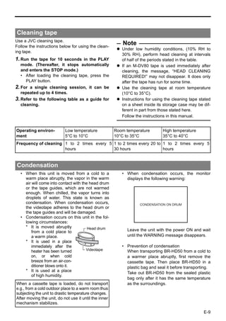
![RECORDING
Backup recording function
In combination with DV equipment, BR-HD50 can perform continuous, long-hour recording.
BR-HD50 can be set as the backup unit connected to a DVcamcorder (GY-DV300/DV500/DV550/
DV5000, etc.). When the recording tape of the source unit nears its end, BR-HD50 can start recording,
enabling long-hour recording.
Backup unit: BR-HD50
IEEE1394 cable
IEEE1394
DV terminal
terminal
INPUT SELECT switch
REMOTE/LOCAL switch
For using GY-DV5000/DV5100 as the
Connection
source unit
Connect the DV terminal of the source unit to the Set DV REC TRIGGER in the OTHERS [1/2]
IEEE1394 terminal of BR-HD50 with an IEEE1394 Menu screen of GY-DV5000/DV5100 to OFF.
cable.
Operation
Setting up BR-HD50
1. Recording begins on the source unit.
Set the INPUT SELECT switch on the * Ensure that recording starts from the begin-
front panel to “HDV/DV”. ning of the recording tape.
Set the REMOTE/LOCAL switch on the 2. BR-HD50 begins recording when the tape of
front panel to “REMOTE”. the source unit nears its end (about 5 min-
utes before the end of the tape).
Set BACKUP REC: DV in the SYSTEM
• BR-HD50 begins recording when the record-
[1/2] Menu screen. ing time of the source unit reaches the time
Use the following settings according to the set by BACKUP REC: DV.
tape length of the source unit.
* For DV or mini DV cassette tape: Memo
25MIN : 30-minute tape In backup recording, BR-HD50 records video/
55MIN : 60-minute tape sound from the source unit.
75MIN : 80-minute tape While this unit is performing backup recording,
115MIN : 120-minute tape continue shooting from the source unit.
175MIN : 180-minute tape The audio mode is the one selected in the
265MIN : 270-minute tape source unit. (32 K/48 K)
OFF : No backup recording Set BACKUP REC: DV to “OFF” if the unit is
Set the REM SEL HDV/DV in the RE- not performing backup recording.
MOTE [1/2] Menu screen to ON or
LOC+REM.
Set TC DUPLI.: DV in the TC/UB/CLOCK
[1/2] Menu screen to OFF.
• It records the data of the built-in time code
generator.
• When TC DUPLI.: DV is set to AUTO or
NON DROP, the time code of the DV cam-
corder will stop advancing. If the DV cable
is disconnected, the time code of the
backup recording will stop advancing.
E-47](https://image.slidesharecdn.com/br-hd50brochure-110419040454-phpapp01/85/JVC-BR-HD50-51-320.jpg)
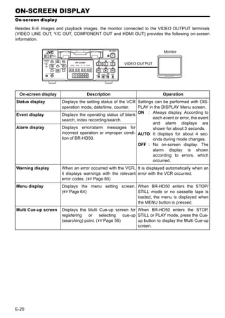
![RECORDING
Recording with SERIAL REMOTE terminals
Recording can be turned ON/OFF with a serial remote controller or foot switch connected to the serial
remote terminal located at the rear panel of BR-HD50.
SERIAL
REMOTE/LOCAL switch REMOTE
• Serial remote controller
• Foot switch
REMOTE [1/2] Menu screen
Connection – – – R E MO T E [ 1 / 2 ] – – –
The serial remote controller can be connected to the SERIAL R E MO T E S E L 9 P ON
R E MO T E S E L S E R ON
REMOTE terminal located on the rear panel of BR-HD50. R EM S E L HD V / D V ON
L OC A L F UNC T I ON STP+EJ T
P R E RO L L 7 SEC
Setting NE X T P AGE
P AGE B ACK
To use the SERIAL REMOTE terminal, set REMOTE
SEL SER in the REMOTE [1/2] Menu screen to ON or
LOC+REM. Then, set the REMOTE/LOCAL switch on
the front panel accordingly. Memo
REMOTE SEL SER Besides recording, the serial
ON : When the REMOTE/LOCAL switch is set to remote controller can per-
REMOTE, operations can be performed via the form other functions.
SERIAL REMOTE terminal. If the REMOTE SEL SER is set
LOC+REM : With the REMOTE/LOCAL switch is set either way, to ON, unit buttons that can be
operations can be performed via the SERIAL operated can be selected from
REMOTE terminal. With this setting, the buttons LOCAL FUNCTION in the
and switches of the unit can be used too. REMOTE [1/2] Menu screen.
Set FOOT SW in the REMOTE [2/2] Menu screen accord- REMOTE [2/2] Menu screen
ing to how the SERIAL REMOTE terminal is used.
– – – R EMO T E [ 2 / 2 ] – – –
OFF : Set to OFF when the serial remote controller is R EM F F / R EW MOD E F F / R EW
used. The footswitch cannot be used. REM S TOP SE L .
PB START DELAY
EE
0F
L EDGE : Recording and recording pause is switched at the SYNCHRON I Z A T I ON ON
CON T ROL L ER SE L TYPE1
LOW edge of the footswitch signal. F OO T SW L EDGE
PAGE BACK
H EDGE : Recording and recording pause is switched at the
HIGH edge of the footswitch signal.
L LEVEL : Recording is performed at the LOW edge and
paused at the HIGH edge of the footswitch signal.
Foot switch
Operation
Signal
Before using the foot switch, set BR-HD50 to the RECORDING or H
RECORDING PAUSE mode using the relevant buttons of the unit. Serial IN
(Only with L EDGE and H EDGE) terminal
L 400ms
Min
Memo
The foot switch can only be used to switch between RECORD-
ING ON and OFF.
The foot switch can be operated regardless of the setting of the
REMOTE/LOCAL switch.
E-48](https://image.slidesharecdn.com/br-hd50brochure-110419040454-phpapp01/85/JVC-BR-HD50-52-320.jpg)
![PLAYBACK
Playback settings
Video settings
This unit plays back tapes recorded in HDV, DV,
or DVCAM format. (SP mode only) Setting VIDEO Menu screen
Selecting video format for HDMI OUT
terminal and COMPONENT OUT terminal
OUT FORMAT [60]/[50]
Select the playback image format to output
from the HDMI OUT terminal and the COMPO-
NENT OUT terminal. (Cross converter video)
[Settings [60]: NATIVE, 480I, 480P, 1080I, 720P]
[Settings [50]: NATIVE, 576I, 576P, 1080I, 720P]
Automatic selection of HDMI OUT ter-
When playing back tapes recorded in HDV or minal video output
DVCAM format, the front panel HDV or DVCAM MONITOR SELECT
indicator is lit. To automatically match the playback image
Selecting playback video format format output from the HDMI OUT terminal to
Set whether to automatically detect the video the video format of the connected display, set
format for playback, or to select a specific for- this menu item to HDMI[A].
mat, using PB TAPE FORMAT on the SYS- [Settings: HDMI[A]/OUT FRMT]
TEM [2/2] Menu screen. Screen display style for up/down-con-
[Settings: AUTO, DV, HDV, DVCAM] verter video
(Details: XPage 69) DOWN CONV. MODE
Setting IEEE1394 terminal output The HDV signal is a wide-screen video signal.
video format When playing a tape recorded in HDV format,
Set the IEEE1394 terminal output video format the output from the LINE OUT terminal and Y/
to HDV or DV. C OUT terminal will be down-converted play-
Set the IEEE1394 switch on the front panel, back images (480i/576i).
according to the playback video format. Set the style for displaying the down-con-
HDV : Use this setting when the playback tape verted playback image on a display with a 4:3
video format is HDV. aspect ratio.
DV : Use this setting when the playback tape This will also apply to down-converted play-
video format is DV or DVCAM. back images (480i/576i) output from the COM-
PONENT OUT terminal.
Memo [Settings: SQUEEZE/LETTER BOX/SIDECUT]
When playing back a tape recorded in HDV
UP CONV. MODE
format, match the unit HD signal format (60Hz
Up-converts DV/DVCAM recorded tape play-
or 50Hz) to the playback signal format.
back signals, and sets the video mode for out-
(XPage 40 “Selecting HD signal format”)
put from the COMPONENT OUT terminal.
Playback output signal format: XPage 34 [Settings: FULL/SIDE P.]
Setting analog signal setup (U model
only)
SET UP [60]: DV
Set enabling or disabling the application of set-
ups to analog video signals (composite, Y/C
separate, and SD component).
VIDEO menu details: XPage 73 to 75
E-49](https://image.slidesharecdn.com/br-hd50brochure-110419040454-phpapp01/85/JVC-BR-HD50-53-320.jpg)
![PLAYBACK
Playback settings (continued)
Audio settings Settings regarding playback
Set audio settings using the AUDIO Menu function
screen. Set various functions in the SYSTEM Menu
Setting AUDIO Menu screen screen.
Selecting output audio channel (DV Setting SYSTEM Menu screen
only) Selecting still pictures or frame-
A.OUTPUT: DV advance playback (DV only)
To play back tapes recorded in the 32 kHz STL/F.ADV: DV
mode, select the output audio channel for the Selects still pictures or frame-advance play-
AUDIO OUT terminal or the PHONES termi- back when playing back DV format video.
nal. In the 48 kHz mode or HDV format, the [Settings : FIELD, 1ST FIELD, 2ND FIELD,
audio of CH1 and CH2 is output regardless of FRAME]
the setting of this menu item. When playing back HDV format video, frame
[Settings: CH-1/2, MIX, CH-3/4] images are output, regardless of the setting of
Selecting audio output during search this menu item.
(DV only) Selecting still mode
A. OUT AT SRH: DV LONG PAUSE TIME
For selecting whether sound is output during For setting the time (minute) when BR-HD50
variable speed playback. In HDV format, audio enters the tape protection mode if BR-HD50 is
is not output during search, regardless of the in the STILL mode for a long time.
setting of this menu item. [Settings: 5, 3, 2, 1 minute or 30 seconds]
[Settings: ON, OFF] LONG PAUSE MODE
Selecting the standard audio output For selecting the state of BR-HD50 when it
level enters the tape protection mode after it stayed
AUDIO OUT LEVEL in the STILL mode for a prolonged period of
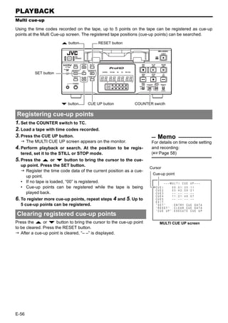
Select the standard audio output level. time.
Set to –12dB to playback tapes recorded at [Settings: F.ADV or STBY-OFF]
–12dB on a home-use DV machine. Selecting Q, S button functions
[Settings: –20dB, –12dB] “Q, S” KEY FUNC.
Selecting V. fade function (DV only) Select whether to use the SEARCH+ (S) and
V.FADE: DV SEARCH– (Q) buttons for index search, or to
Select whether to fade the audio during play- change the search speed.
back at jointed portions of recording. No fading [Settings : INDEX, VAR/RECV]
occurs for HDV format. Selecting repeat playback function
[Settings: OFF, ON] REPEAT MODE
This mode is for turning ON/OFF the REPEAT
PLAYBACK function and selecting the type of
REPEAT PLAYBACK. If REPEAT PLAYBACK
is not performed, set it to OFF.
[Settings: OFF, INDEX, V. END, TAPE END]
E-50](https://image.slidesharecdn.com/br-hd50brochure-110419040454-phpapp01/85/JVC-BR-HD50-54-320.jpg)
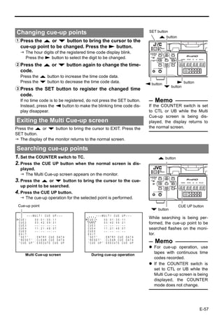
![PLAYBACK
Basic playback procedure
PLAY button
PAUSE button
FF button
REW button STOP button
1. Load a recorded cassette tape.
The power for BR-HD50 is turned on. Note
2. Start playback. Tapes recorded in the LP mode
cannot be played. The monitor
Press the PLAY button.
Playback starts. displays an alarm message:
When playing back tapes recorded in HDV format, the front “LP TAPE!”
panel HDV indicator is lit.
When the tape is recorded in DVCAM format, the DVCAM Memo
indicator is lit. Press the DISPLAY button
3. Pause the tape. during PLAY mode to dis-
Press the PAUSE button. play the playback video for-
A still image is output. mat on the counter display.
Memo When output of still image
The still image selected with STL/F.ADV: DV in the SYSTEM [1/2] continues for a prolonged
Menu screen is output. (1st field image/ 2nd field image/ frame period, BR-HD50 enters the
image) tape protection mode.
Playback of HDV format tapes is always in frame image output.
Playback of tapes recorded
4. Resume playback.
Press the PLAY button.
in HDV format
5. Stop playback. Set 60/50 SEL in the SYSTEM
Press the STOP button. [2/2] Menu screen, according
to the HD signal format. (60Hz
Fast forward/rewind or 50Hz)
When BR-HD50 is in the STOP mode, press the FF IEEE1394 terminal output
button to fast-forward the tape. signal
When BR-HD50 is in the STOP mode, press the REW To use the IEEE1394 terminal
button to rewind the tape. output signal, set the front
panel IEEE1394 switch accord-
ing to the video format of the
playback tape. (HDV or DV)
E-51](https://image.slidesharecdn.com/br-hd50brochure-110419040454-phpapp01/85/JVC-BR-HD50-55-320.jpg)
![PLAYBACK
Special playback functions
PAUSE button
Frame-advance playback
Setting
STL/F. ADV: DV in the SYSTEM [1/2] Menu screen SYSTEM [1/2] Menu screen
The unit of frame advance and still images can be selected. (DV – – – SYS T EM [ 1 / 2 ] – – –
ST L / F . ADV : DV 2ND
format only) BACKUP REC : DV OFF
LONG PAUSE T I ME 3 0SEC
FIELD : Field-by-field advance REC LONG P . T I ME 5M I N
1st FIELD : Frame-by-frame advance and stops at the 1st L ONG P A U S E MOD E S T BY - OF F
“ , ” KEY FUNC . VAR / RECV
field. R E P E A T MOD E
NEXT PAGE
OF F
2nd FIELD : Frame-by-frame advance and stops at the 2nd PAGE BACK
field.
FRAME : Frame-by-frame advance.
• Does not frame-advance when playing back an HDV tape.
Operation
1. Set BR-HD50 to the STILL mode.
2. Press the PAUSE button to perform frame advance.
E-52](https://image.slidesharecdn.com/br-hd50brochure-110419040454-phpapp01/85/JVC-BR-HD50-56-320.jpg)
![SEARCH–/Q button SEARCH+/S button
REW button FF button
Slow playback and Search mode
Setting Memo
Whether to enable/disable
Set “Q, S” KEY FUNC in the SYSTEM [1/2] Menu
audio out in the Slow play-
screen to VAR/RECV.
back or SEARCH mode can
Operation be selected with A. OUT AT
SRH: DV in the AUDIO
1. Set BR-HD50 to the PLAYBACK or the STILL mode. Menu screen.
2. Press the FF button to start fast-forward playback. Search audio is not output
Press the REW button to start reverse playback. for HDV format.
Press the SEARCH+/S button to increase the Playback at ± 0.1 × speed is
search speed. Every time you press this button, the step-slow playback (continu-
speed increases more. ous frame-advance play-
back/frame-reverse
Press the SEARCH–/Q button to decrease the playback).
search speed. Every time you press this button, the In step-slow playback, video
speed decreases more. is output according to the
STL/F.ADV: DV setting in
Search speed the SYSTEM [1/2] Menu
SEARCH+/S button (Fast) (Slow) SEARCH–/Q button screen. (DV format only)
DV recorded tape playback When step-slow playback is
×–20··×–9 (U)/ –10(E)··×–5··×–2··×–1··×–0.5··×–0.33·· continued, the speed is
×–0.2··×–0.1··STILL··×0.1··×0.2··×0.33··×0.5··×1(PLAY)·· automatically set to ±0.2×.
×2··×5··×9 (U)/10 (E)··×20 During slow-playback or
(U): U model frame-advance, noise is
(E): E model generated to the output
* The maximum speed in the DVCAM mode is 15×. images from the IEEE1394
HDV recorded tape playback terminal. For recording slow-
×–16··×–6.5··×–4.5··×–2.5··×–1.5··STILL··×1(PLAY)·· playback images, use ana-
×2.5··×5.5··×8.5··×18 log output signals of BR-
HD50.
• Cannot perform slow playback when playing back an HDV
tape.
E-53](https://image.slidesharecdn.com/br-hd50brochure-110419040454-phpapp01/85/JVC-BR-HD50-57-320.jpg)
![PLAYBACK
Search function
Index search
This function searches to the position where the index signal is recorded.
Setting
Set “Q, S” KEY FUNC in the SYSTEM [1/2] Menu screen
to INDEX.
Operation
To search an index point in the forward direction
from the current tape position:
• Press the SEARCH+ button. SEARCH SEARCH
The index position to be searched can be specified by the – button + button
number of times this button is pressed. (Max: 99)
To search an index point in the reverse direction Monitor screen
from the current tape position:
• Press the SEARCH– button.
The index position to be searched can be specified by the
number of times this button is pressed. (Max: 99) INDEX+1
When the SEARCH+ or SEARCH– button is pressed,
the unit fast-forwards or rewinds to the specified
indexed position and start playing.
Index search progressing:
Memo displayed on the screen
If the interval between index signals is less than one minute, the (The number denotes the corre-
function may not work well. sponding index position.)
The specifications for index signal recording varies with the
device used.
Blank search
This function searches unrecorded parts of the tape.
In the STOP mode, press the BLANK button.
• If the current position is at a recorded part of the tape, BR-
HD50 fast-forwards until an unrecorded part is reached
and stops there.
• If the current position is an unrecorded part of the tape,
BR-HD50 will first advance the tape in the forward direc-
tion for confirmation and thereafter rewind and go into the
STILL mode at the last recorded position. BLANK button
• During a blank search, “BLANK SEARCH” is displayed on Monitor screen
the monitor.
BLANK SEARCH
E-54](https://image.slidesharecdn.com/br-hd50brochure-110419040454-phpapp01/85/JVC-BR-HD50-58-320.jpg)
![PLAYBACK
Repeat playback
Three types of repeat playback are available for BR-HD50.
The repeat playback function can be set with REPEAT MODE in the SYSTEM [1/2] Menu screen.
SYSTEM [1/2] Menu screen
Setting
– – – SYS T EM [ 1 / 2 ] – – –
REPEAT MODE in the SYSTEM [1/2] Menu screen ST L / F . ADV : DV 2 ND
OFF : No repeat playback. BACKUP REC : DV OFF
LONG PAUSE T I ME 3 0SEC
INDEX : Repeat playback between positions where index REC LONG P . T I ME 5MI N
L ONG P A U S E MOD E STBY - OFF
signals are recorded. “ , ” KEY FUNC . VAR / RECV
R E P E A T MOD E I NDE X
V. END : Repeat playback from the beginning of the tape to NEXT PAGE
the position where recording of video signals PAGE BACK
ends.
TAPE END : Repeat playback from the beginning to the end of
the tape.
Operation INDEX repeat playback
1. Press the REW button to rewind the tape to the beginning. If no index signal is
2. Press the PLAY button to start playback. detected during playback,
When it reaches the position set at REPEAT MODE, the tape the tape will run until the
starts rewinding and plays back again. end. If no index signal is
detected during rewind, the
To abort the repeat playback function, press the tape will rewind until the
STOP button. beginning.
If the interval between
Repeat operation index signals is less than
one minute, the function
may not work well.
TAPE END
Memo
V. END If the head is dirty, repeat play-
back may not work well.
INDEX Playback
Rewind
Index signal Index signal
Beginning of tape End of tape
E-55](https://image.slidesharecdn.com/br-hd50brochure-110419040454-phpapp01/85/JVC-BR-HD50-59-320.jpg)
![TIME CODE
Displaying the time code
This unit records or plays back the time code and user’s bit. Whether to record the user’s bit can be
selected with U-BIT in the TC/UB/CLOCK [2/2] Menu screen (only for E model). With the time code
function, accurate positions of the tape contents can be specified to enhance editing precision and
operation efficiency. During recording or playback, the time code and user’s bit are displayed on the
monitor or the Counter display.
Status display (Monitor)
TCG : Time code generator data
DV 3 2 K CH – 1 / 2 SP 6 0M I N
TCR : Time code reader data
WA RN I NG 7 0 0 1
DTCG : Input time code data from D R UM MO T O R F A I L U R E
the IEEE1394 terminal Framing mode
REC I NH I B I T
UBG : User’s bit generator data (for NTSC only)
UBR : User’s bit reader data : (colon) : Non-drop frame
06 / 10 / 05 S T ANDB Y -OF F 1
10 : 20 : 00 T CR 0 2 : 0 0 : 0 0 : 0 0
DUBG : User’s bit input data from . (dot) : Drop frame
the IEEE1394 terminal
Time code/User’s bit display
During recording and stop mode: Data of time code generator
During playback : Data recorded on the tape
During DV input : Data selected with TC DUPLI.:
DV in the TC/UB/CLOCK
Menu screen
To display the time code/ user’s bit, perform the fol- DISPLAY Menu screen
lowing settings. – – –D I SPLAY– – –
D I SPLAY ON
• Set DISPLAY in the DISPLAY Menu screen to ON or AUTO. COUN T ER POS I . L OW E R - R
T I ME CODE ON
The status is displayed on the monitor. V T R MOD E ON
• Set TIME CODE in the DISPLAY Menu screen to ON. T APE REMA I N
T I ME / DA T E
ON
DATE + TM
The time code, user’s bit or CTL counter is displayed at the A/V I NFO . ON
DATE STYLE D D / MM / Y Y
counter display section of the status display. T I ME S T Y L E 2 4 HOUR
PAGE BACK
• Select the counter display mode with the COUNTER switch
on the front panel.
The display position can be
To display the time code, select TC.
selected.
To display the user’s bit, select UB.
Checking the data of time code generator
When it is in the STOP mode, press the REC button and the data
of the time code generator will be displayed while the button is
held down.
COUNTER switch
E-58](https://image.slidesharecdn.com/br-hd50brochure-110419040454-phpapp01/85/JVC-BR-HD50-62-320.jpg)
![TIME CODE
Presetting the time code
Variable values can be set for the time code and the user’s bit for efficient material management and
editing.
SET button
DISP/R button RESET button
Q button
HOLD button P button S button COUNTER switch
TC/UB/CLOCK[1/2] Menu screen
Setting ...TC/UB/CLOCK [1/2] Menu screen
Set TCG SELECT to “PRESET”. – – – TC / UB / C LOCK [ 1 / 2 ]–––
TCG SE L EC T PRESET
The time code advance mode is REC-RUN mode. NDF / DF [ 6 0 ] DROP
DF B I T [ 5 0 ] ON
REC-RUN : The time code runs only during recording. TC DUP L I . : DV OFF
TC OFFSET OFF
NDF/DF [60] (U model only) NEXT PAGE
PAGE BACK
NON-DROP: Enters non-drop frame mode. Use this setting
when emphasizing the frame count.
DROP : Enters drop-frame mode. Use this setting when
emphasizing the recording time.
Operation ...Perform setting while checking the Counter display. Memo
This section describes the setting of the time code. The setting of To stop the setting, press
the user’s bit is the same. Values that can be used to configure the the HOLD button to return to
user’s bit are hexadecimal numeral from 0 - F. the normal screen.
To preset all digits to 0, press
1. Set the COUNTER switch to TC. the RESET button when any
(For user’s bit, set the switch to UB.)
of the digits is blinking.
2. In the STOP mode, press the HOLD button. When the hour digit is blink-
The hour digit of the counter starts blinking. ing, the frame digit starts
3. Press the R or P button to change the value. blinking when the Q button
4. Press the S or Q button to move blinking to the next is pressed.
digit. If a user’s bit is input with its
5. Press the R or P button to change the value of the blink- all digits set as “F”, BR-HD50
ing digit. converts FFFFFFFF to
6. Repeat steps 4 and 5 to perform the necessary settings. FFFFFFFE before recording.
7. Press the SET button to confirm the setting value and
blinking of the counter stops.
The setting is preset to the time code generator.
E-59](https://image.slidesharecdn.com/br-hd50brochure-110419040454-phpapp01/85/JVC-BR-HD50-63-320.jpg)
![TIME CODE
Recording the time code
Time codes can be recorded with the following ways. Whether to record user’s bit can be selected with
U-BIT in the TC/UB/CLOCK [2/2] Menu screen. (Only for E model)
Record it from preset data.
Record it following the one last recorded on the tape.
Record the time code, which is input to the IEEE1394 terminal. (In DV mode only)
Recording from preset data
Record preset time code data to the internal time code generator in the TIME CODE Preset screen.
TC/UB/CLOCK [1/2] Menu screen
Setting
– – – TC / UB / C LOCK [ 1 / 2 ]–––
Set the TC/UB/CLOCK [1/2] Menu as follows. TCG SE L EC T PRESET
NDF / DF [ 6 0 ] DROP
TCG SELECT : PRESET DF B I T [ 5 0 ] ON
TC DUP L I . : DV OFF
The time code advance mode is REC-RUN mode. TC OFFSET OFF
NDF/DF [60] : NON DROP or DROP (U model only) NEXT PAGE
PAGE BACK
Operation
1. Check the preset time code.
1 Set the COUNTER switch to TC or UB.
2 In the STOP mode, hold down the REC button.
The preset time code or the user’s bit is displayed on the REC button
monitor. The counter mode is displayed as TCG or UBG.
3 When the REC button is released, it returns to the origi-
nal display.
2. Record.
Press the PLAY button while holding down the REC button.
The time code and user’s bit are recorded.
To stop recording, press the STOP button.
Preset time code
COUNTER switch
Stopping the power supply to the DV IN terminal of BR-HD50 can-
cels the preset value of the time code generator.
E-60](https://image.slidesharecdn.com/br-hd50brochure-110419040454-phpapp01/85/JVC-BR-HD50-64-320.jpg)
![Recording time code following the one last recorded on the tape
BR-HD50 is equipped with a time code reader. When it enters the RECORD mode from the RECORD-
ING PAUSE mode, it reads the time code data already recorded on the tape and continues recording
time code from that value. (Regeneration)
TC/UB/CLOCK [1/2] Menu screen
Setting
– – – TC / UB / C LOCK [ 1 / 2 ]–––
Set the TC/UB/CLOCK [1/2] Menu as follows. TCG SE L EC T REGEN
NDF / DF [ 6 0 ] DROP
TCG SELECT : REGEN DF B I T [ 5 0 ] ON
TC DUP L I . : DV OFF
NDF/DF [60] : No setting required. The framing mode will TC OFFSET OFF
NEXT PAGE
match the tape. (U model only) PAGE BACK
Operation
1. Insert a tape with time codes recorded.
2. Set BR-HD50 to the RECORDING PAUSE mode at the posi-
tion where time codes are to be recorded again.
3. Press the PLAY button to go to the RECORDING mode.
Time codes will be recorded on the tape, starting from where
it stopped at last recording.
The counter mode display shows either TCR or UBR.
Recording time code, input to the IEEE1394 terminal (In DV mode only)
TC/UB/CLOCK [1/2] Menu screen
Setting
– – – TC / UB / C LOCK [ 1 / 2 ]–––
Set the INPUT SELECT switch on the front panel to TCG SE L EC T PRESET
NDF / DF [ 6 0 ] DROP
HDV/DV. DF B I T [ 5 0 ] ON
TC DUP L I . : DV AUTO
TC OFFSET OFF
Set TC DUPLI.: DV in the TC/UB/CLOCK [1/2] Menu NEXT PAGE
PAGE BACK
screen to AUTO.
* To record the time code from a BR-DV600 or GY-DV500 in
non-drop frame mode, set TC DUPLI.: DV to NON DROP. (U
model only)
Operation
1. Check the time code of the IEEE1394 terminal.
Press the REC button when BR-HD50 is in the STOP mode to
display the time code on the monitor. It will be displayed while
the button is held down.
The counter mode display shows DTCG or DUBG.
2. Select the RECORDING mode.
Record time codes from the IEEE1394 terminal.
Memo
For date/time also, data from the IEEE1394 terminal are recorded.
E-61](https://image.slidesharecdn.com/br-hd50brochure-110419040454-phpapp01/85/JVC-BR-HD50-65-320.jpg)
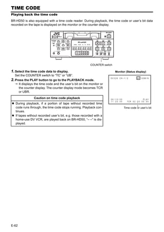
![EDIT
Using a non-linear editing system
Tape contents of BR-HD50 are captured by a non-linear editing system and the non-linear edited con-
tents are recorded on BR-HD50.
Connection
Analog video
VIDEO OUT Analog audio
AUDIO OUT
RS-422A
REMOTE
Non-linear system
IEEE1394 terminal
IEEE1394 (image, audio, control)
Control with RS-422A Control with the IEEE1394 ter-
(Analog signals) minal (Digital signals)
Setting Setting
Set the REMOTE/LOCAL switch on the Set the INPUT SELECT switch located
front panel to REMOTE. on the front panel to HDV/DV.
REMOTE [1/2] Menu screen Set the IEEE1394 switch located on
• Set REMOTE SEL 9-PIN to “ON”. the front panel to match the video for-
REMOTE [2/2] Menu screen mat.
REMOTE FF/REW MODE: • Set to DV position for DV mode, and to
Use this item to select the operation to be per- HDV position for HDV mode.
formed if the FF or REW command is received Set the REMOTE/LOCAL switch on the
during playback. (FF/REW or Search) front panel to the position matching
If the search operation is not performed prop- the REMOTE menu below.
erly, set it to “SEARCH”.
CONTROLLER TYPE (in the REMOTE [2/2]
REMOTE [1/2] Menu screen
• Set REM SEL HDV/DV to ON or LOC+REM.
Menu screen):
Set this item to ON if it is to become
Set this item to “TYPE1”.
enabled only when the REMOTE/LOCAL
switch on the front panel is set to REMOTE.
Set this item to LOC+REM if it is to become
enabled regardless of the position of the
REMOTE/LOCAL switch.
Memo
If the time code of BR-HD50 is not displayed correctly when the non-linear side moves one frame
forward or backward, set the STL/F.ADV: DV in the SYSTEM [1/2] Menu screen to “FRAME.” (In DV
mode only)
When controlling with RS-422A using the HDV format, only the capture operation is supported.
E-63](https://image.slidesharecdn.com/br-hd50brochure-110419040454-phpapp01/85/JVC-BR-HD50-67-320.jpg)
![MENU SCREENS
Setting the menus
The functions of BR-HD50 are configured in the Menu screens. The configured settings are saved in
the memory of BR-HD50 and retained even after power off.
MENU button R button
SET button
Q button
P button S button
Perform the menu settings while viewing the display on the moni- TOP Menu screen
tor. – – –MENU – – –
The counter display shows menu code numbers. SYS T EM . .
R EMO T E . .
Set BR-HD50 to the STOP or STILL mode. AUD I O . .
V I DEO . .
TC / UB / C LOCK . .
1. Displaying the TOP MENU screen. D I SPLAYSET . .
EX I T
Press the MENU button.
2. Displaying the Menu screen items for setting.
1 Press the R or P button to bring the cursor to the Menu
screen item for setting. Cursor Menu Items
2 Press SET or the S button.
Select EXIT of the TOP Menu screen to return to the normal
screen.
3. Setting the Menu item for setting. Cursor Item Setting value
1 Press the R or P button to bring the cursor to the Menu
screen item for setting. – – – SYS T EM [ 1 / 2 ] – – –
2 Press SET or the S button. ST L / F . ADV : DV
BACKUP REC : DV
2ND
OFF
The selected setting value blinks and becomes available LONG PAUSE T I ME 3 0SEC
REC L ONG P . T I ME 5M I N
for changing. L ONG P A U S E MOD E STBY - OFF
“ , ” KEY FUNC . VAR / RECV
3 Press the R or P button to change the value. R E P E A T MOD E OFF
NEXT PAGE
4 Press the SET button to confirm the change. PAGE BACK
Blinking stops and the new value is confirmed.
5 Repeat steps 1 - 4 and continue setting as necessary.
E-64](https://image.slidesharecdn.com/br-hd50brochure-110419040454-phpapp01/85/JVC-BR-HD50-68-320.jpg)
![To display the Menu screen at the next level, bring SYSTEM [1/2] Menu screen
the cursor to NEXT PAGE and press the SET or S – – – SYS T EM [ 1 / 2 ] – – –
button. ST L / F . ADV : DV
BACKUP REC : DV
2ND
OFF
LONG PAUSE T I ME 3 0SEC
To return to the previous Menu screen, do one of the REC L ONG P . T I ME 5M I N
L ONG P A U S E MOD E STBY - OFF
following actions. “ , ” KEY FUNC . VAR / RECV
R E P E A T MOD E OFF
• Press the S button. NEXT PAGE
PAGE BACK
Or
• Select PAGE BACK and press the SET or S button.
4. To return to the normal screen, do one of the following – – – SYS T EM [ 1 / 2 ] – – –
actions. ST L / F . ADV : DV
BACKUP REC : DV
2ND
OFF
• Press the MENU button. LONG PAUSE T I ME 3 0SEC
REC LONG P . T I ME 5M I N
Or L ONG P A U S E MOD E STBY - OFF
“ , ” KEY FUNC . V AR / RECV
• Select EXIT in the TOP Menu screen and press the SET or R E P E A T MOD E OFF
NEXT PAGE
S button. PAGE BACK
Menu screen on counter display
SYSTEM [2/2] Menu screen
The counter display shows menu code numbers when setting
menus.
01 05 00
Setting value
Items
Menu screen
(Example) 01: SYSTEM Menu screen
• Menu display : Flashes when the TOP MENU screen is dis-
played.
• Items : Flashes when each menu screen is displayed.
(No settings are selected yet.)
• Setting : Flashes when a menu item is selected and the
setting on the monitor display is flashing.
E-65](https://image.slidesharecdn.com/br-hd50brochure-110419040454-phpapp01/85/JVC-BR-HD50-69-320.jpg)
![MENU SCREENS
Structure of the Menu screens
The Menu screens are displayed on the monitor. They are structured with multiple layers.
SYSTEM [1/2] menu SYSTEM [2/2] menu
– – – SYS T EM [ 1 / 2 ] – – – – – – – – – SYS T EM [ 2 / 2 ] – – – – – –
ST L / F . ADV : DV 2ND D C I N MOD E OPE OF F
BACKUP REC : DV OFF I N D E X WR I T E ON
LONG PAUSE T I ME 3 0SEC OPERA T I ON LOCK OFF
REC L ONG P . T I ME 5M I N 6 0 / 5 0 SEL 50
L ONG P A U S E MOD E STBY - OFF F AC TORY SE T T I NG CANCE L
“ , ” KEY FUNC . VAR / REC DRUM HOUR ME T E R 000000
V R E P E A T MOD E OFF PAGE BACK
NEXT PAGE
PAGE BACK
REMOTE [1/2] menu REMOTE [2/2] menu
– – – R E MO T E [ 1 / 2 ] – – – – – – R EMO T E [ 2 / 2 ] – – –
R E MO T E S E L 9 P ON R EM F F / R EW MOD E F F / R EW
R E MO T E S E L S E R ON REM S TOP SE L . EE
R EM S E L HD V / D V ON PB START DELAY 0F
L OC A L F UNC T I ON STP+EJ T SYNCHRON I Z A T I ON ON
P R E RO L L 7 SEC CON T ROL L ER SE L TYPE1
NE X T P AGE F OO T SW OFF
P AGE B ACK PAGE BACK
Top menu AUDIO menu
– – –MENU – – – – – – AUD I O– ––
SYS T EM . . A U D I O MOD E : D V 48K
R EMO T E . . A . OU T PU T : DV CH1 / 2
AUD I O . . A . OU T A T SRH : DV ON
V I DEO . . AUD I O OU T L EV - 20dB
T C / UB / C LOCK . . V . FADE : DV ON
D I SPLAYSET . . A . R E C V R . MD . : D V BOTH
EX I T PAGE BACK
VIDEO menu
– – – V I DEO– – –
SET UP [ 6 0 ] : DV ON
Normal screen MON I T OR S E L E C T HDM I [ A ]
OU T F ORMA T [ 6 0 ] NAT I VE
OU T F ORMA T [ 5 0 ] NAT I VE
D OWN C O N V . M O D E SQUE E Z E
U P CON V . MODE FUL L
H DM I MOD E AUTO
DV I COLOR STANDARD
T ES T S I GNA L OFF
PAGE BACK
TC/UB/clock [1/2] menu TC/UB/clock [2/2] menu
– – – T C / UB / C L OCK [ 1 / 2 ] ––– – – – TC / UB / C LOCK [ 2 / 2 ] – – –
TCG SE L ECT REGEN U-BI T [ 50 ]
NDF / DF [ 6 0 ] DROP C L OCK AD J US T . .
DF B I T [ 5 0 ] ON PAGE BACK
TC DUP L I . : DV OFF
TC OFFSET OFF
NEXT PAGE
PAGE BACK
DISPLAY menu CLOCK ADJUST menu
– – –D I SPLAY– –– – – – C LOCK AD J US T – – –
D I SPLAY ON D A T E ( D D / MM / Y Y ) 06 / 10 / 05
COUNT ER POS I . L OW E R - R T I ME 00 : 00
T I ME CODE ON PAGE BACK
V T R MOD E ON
T APE REMA I N ON
T I ME / DA T E DA T E + TM
A / V I NFO . ON
DATE STYLE D D / MM / Y Y
T I ME S T Y L E 2 4 HOUR
PAGE BACK
E-66](https://image.slidesharecdn.com/br-hd50brochure-110419040454-phpapp01/85/JVC-BR-HD50-70-320.jpg)
![MENU SCREENS
Description of the Menu screens
In the following description of the Menus, E indicates factory settings.
Numbers in parentheses by items and settings are the code number shown on the counter display.
TOP Menu screen
Item Setting Description
SYSTEM.. Displays the menus related to the operating system of BR-HD50.
–
It also displays factory setting and the drum hour meter.
REMOTE.. – Displays the menus related to the remote controller.
AUDIO.. – Displays the menus related to the audio.
VIDEO.. – Displays the menus related to the video.
TC/UB/CLOCK.. Displays the menu for setting time codes.
–
Also displays the date/time setting screen.
DISPLAYSET.. – Displays menus related to on-screen display.
EXIT – Return to the normal screen.
SYSTEM Menu screens
The SYSTEM Menu consists of the following two screens (1/2 and 2/2).
SYSTEM [1/2] Menu screens
Item Setting Description
STL/F.ADV: DV FIELD (00) Use this setting to select the still image for the STILL mode or
(0100) 1ST (01) frame-advance playback. (During DV format video playback)
E2ND (02) FIELD : Displays the field image. During frame-advance play-
FRAME (03) back, it displays the 1st and 2nd field images alternately.
1ST : Displays the 1st field image.
2ND : Displays the 2nd field image.
FRAME: Displays the frame image.
Memo
Playback of HDV format tapes is always in frame image output,
regardless of menu settings.
The first field image is displayed as the DV output image from
the IEEE1394 terminal, regardless of the settings.
BACKUP REC EOFF (00) For setting backup recording time with DV input signals according
: DV 25MIN (01) to the tape length of the source unit:
(0101) 55MIN (02) OFF : No backup recording
75MIN (03) 25MIN : For a 30-minute source unit recording tape
115MIN (04) 55MIN : For a 60-minute source unit recording tape
175MIN (05) 75MIN : For a 80-minute source unit recording tape
265MIN (06) 115MIN : For a 120-minute source unit recording tape
175MIN : For a 180-minute source unit recording tape
265MIN : For a 270-minute source unit recording tape
(XPage 47 “Backup recording function”)
Memo
Set this item to “OFF” if DV REC TRIGGER of GY-DV5000/
DV5100 is set to ON.
E-67](https://image.slidesharecdn.com/br-hd50brochure-110419040454-phpapp01/85/JVC-BR-HD50-71-320.jpg)
![MENU SCREENS
Description of the Menu screens (continued)
SYSTEM Menu screens (continued)
Item Setting Description
LONG PAUSE E30SEC (00) Select the time when BR-HD50 enters the TAPE PROTECTION
TIME 1MIN (01) mode if the unit has stayed at still or stop for a prolonged period of
(0102) 2MIN (02) time. The TAPE PROTECTION mode in at STILL can be selected
3MIN (03) from LONG PAUSE MODE:
5MIN (04) 30SEC : 30 seconds
1MIN : 1 minute 3MIN : 3 minutes
2MIN : 2 minutes 5MIN : 5 minutes
Memo
To prevent the video head from clogged or the tape from being
damaged, set as short a time as possible.
REC LONG 30SEC (00) Select the time when BR-HD50 enters the TAPE PROTECTION
P.TIME 1MIN (01) mode if the unit has stayed at recording pause for a prolonged
(0103) 2MIN (02) period of time.
3MIN (03) 30SEC : 30 seconds
E5MIN (04) 1MIN : 1 minute 3MIN : 3 minutes
2MIN : 2 minutes 5MIN : 5 minutes
Memo
To prevent the video head from clogged or the tape from being
damaged, set as short a time as possible.
LONG PAUSE F.ADV (00) For selecting the action when BR-HD50 stays at still for a long time.
MODE ESTBY-OFF (01) In the case of RECORDING PAUSE or STOP, it enters the
(0104) STANDBY-OFF status:
F.ADV : Frame-advances BR-HD50 five times in the forward
direction. On the 6th attempt, this mode stops it.
STBY-OFF : Stops BR-HD50.
“Q,S” KEY INDEX (00) For selecting the function for the SEARCH+/S button and
FUNC. EVAR/RECV SEARCH–/Q button.
(0105) (01) INDEX : Performs index search. (XPage 54)
VAR/RECV : Changes the search speed during a search. (XPage 53)
Enables adjusting analog audio input level. (XPage 44)
REPEAT MODE EOFF (00) For enabling/disabling repeat playback and selecting the type of
(0106) INDEX (01) repeat playback.
V. END (02) OFF : No repeat playback
TAPE END (03) INDEX : Repeat playback between the positions where
index signals are recorded.
V. END : Repeat playback from the beginning of the tape to
the position where video signal recording ends.
TAPE END : Repeat playback from the beginning to the end of
the tape.
NEXT PAGE For displaying the SYSTEM [2/2] Menu screen.
PAGE BACK For returning to the TOP Menu screen.
E-68](https://image.slidesharecdn.com/br-hd50brochure-110419040454-phpapp01/85/JVC-BR-HD50-72-320.jpg)
![SYSTEM [2/2] Menu
Item Setting Description
DC IN MODE EOPE OFF (00) For selecting the action to perform when the power is supplied to
(0107) OPE ON (01) the DC IN terminal:
OPE OFF : Sets BR-HD50 to the OPERATE OFF mode.
OPE ON : Sets BR-HD50 to the OPERATE ON mode.
INDEX WRITE OFF (00) For enabling/disabling index signal recording.
(0108) EON (01) OFF : No index signal
ON : Select here to record index signals.
It records an index signal automatically at the position
where recording starts.
OPERATION EOFF (00) For enabling/disabling OPERATION LOCK.
LOCK ON (01) OFF : Turns off OPERATION LOCK and the operation buttons of
(0109) BR-HD50 can be used.
ON : Turns on OPERATION LOCK. The operation buttons and
slide switches of BR-HD50 are disabled except the OPER-
ATE ON button and MENU operation. (XPage 36)
60/50 SEL 60 (00) Sets HD video signal format to 60Hz or 50Hz.
(010A) 50 (01) This menu item applies only to HDV format.
This must be set in the following situations.
• Set this menu item to match the input video signal format when
inputting HDV signals to the IEEE1394 terminal.
• Set this menu item to match the video format recorded on the
tape when playing a tape recorded with HDV signals.
60 : The HD signal format becomes 60Hz.
50 : The HD signal format becomes 50Hz.
[Settings upon shipping: U model: 60, E model: 50]
Memo
The unit restarts when this menu setting is changed.
The front panel 60 or 50 indicator is lit, according to this menu setting.
Recording and playback are unavailable when this menu setting dif-
fers from the HDV input signal or HDV recorded tape signal format.
During DV/analog signal input or when playing a tape recorded with DV/
analog signals, the field frequency format is fixed for the region, regard-
less of this menu setting. [U model: 60Hz (NTSC), E model: 50Hz (PAL)]
FACTORY SET- ECANCEL (00) For enabling/disabling the factory setting for the Menu screens.
TING EXECUTE (01) CANCEL : Disable the factory setting
(010b) EXECUTE: Enable the factory setting
Memo
The unit restarts when this menu setting is executed.
PB TAPE EAUTO (00) Selects whether to automatically detect playback tape video for-
FORMAT DV (01) mat, or to playback only a specific format.
(010c) HDV (02) AUTO : Automatically detects and plays back all video formats.
DVCAM (03) DV : Plays back only video in DV format.
HDV : Plays back only video in HDV format.
DVCAM : Plays back only video in DVCAM format.
Memo
When set to a specific format and a tape with a different format
is played back, there will be noise in the video.
If you play back a tape containing both DV and HDV formats,
the video signal is disturbed when the signal is switched.
DRUM HOUR For displaying the time of drum usage.
METER * The cursor cannot be brought to this item.
PAGE BACK For returning to the SYSTEM [1/2] Menu screen.
E-69](https://image.slidesharecdn.com/br-hd50brochure-110419040454-phpapp01/85/JVC-BR-HD50-73-320.jpg)
![MENU SCREENS
Description of the Menu screens (continued)
REMOTE Menu screens
The REMOTE Menu consists of the following two screens (1/2 and 2/2).
REMOTE [1/2] Menu screen
Item Setting Description
REMOTE SEL OFF (00) For enabling/disabling the REMOTE terminal when the REMOTE/
9P EON (01) LOCAL switch on the front panel is set to REMOTE.
(0200) OFF : Control through RS-422A disabled.
ON : Control through RS-422A enabled.
REMOTE SEL OFF (00) For enabling/disabling control via the SERIAL REMOTE terminal.
SER EON (01) OFF : Control disabled regardless of the settings of the
(0201) LOC+REM (02) REMOTE/LOCAL switch.
ON : Control enabled only when the REMOTE/LOCAL
switch is set to REMOTE.
LOC+REM : Control enabled regardless of the settings of the
REMOTE/LOCAL switch.
REM SEL OFF (00) For enabling/disabling control via the IEEE1394 terminal.
HDV/DV EON (01) OFF : Control disabled regardless of the settings of the
(0202) LOC+REM (02) REMOTE/LOCAL switch.
ON : Control enabled only when the REMOTE/LOCAL
switch is set to REMOTE.
LOC+REM : Control enabled regardless of the settings of the
REMOTE/LOCAL switch.
LOCAL NO KEY (00) For selecting the buttons of BR-HD50 to be enabled in remote-
FUNCTION EJECT (01) controlling it with the REMOTE terminals or the SERIAL REMOTE
(0203) ESTP+EJT (02) terminal:
ALL KEYS (03) NO KEY : No button enabled.
EJECT : Only the EJECT button enabled.
STP + EJT : Only the STOP button and the EJECT button are
enabled.
ALL KEYS : All operation buttons are enabled.
Memo
If OPERATION LOCK in the SYSTEM [2/2] Menu screen is set to
ON, the buttons on BR-HD50 will be disabled regardless of the
setting here.
PREROLL 3SEC (00) For setting the preroll time of BR-HD50 in remote-controlling it
(0204) 5SEC (01) with the REMOTE terminal. Setting done with the editing remote
E7SEC (02) controller prevails over other settings:
10SEC (03) 3SEC : 3 seconds 7SEC : 7 seconds
5SEC : 5 seconds 10SEC: 10 seconds
Memo
To enhance editing precision, please set it to at least 7 seconds.
NEXT PAGE For displaying the REMOTE [2/2] Menu screen.
PAGE BACK For returning to the TOP Menu screen.
E-70](https://image.slidesharecdn.com/br-hd50brochure-110419040454-phpapp01/85/JVC-BR-HD50-74-320.jpg)
![REMOTE [2/2] Menu screen
Item Setting Description
REM FF/REW EFF/REW (00) For setting the action to be performed when the REMOTE termi-
MODE SEARCH (01) nal or IEEE1394 terminal received an FF/REW command:
(0205) FF/REW : Sets BR-HD50 to perform FF/REW when an FF/REW
command is received. Normal setting.
SEARCH : Sets BR-HD50 to perform searching when an FF/
REW command is received. Use this setting if the
search (cue up) function does not work properly.
REM STOP SEL EEE (00) For setting the action to be performed when the REMOTE termi-
(0206) PB (01) nal received a STANDBY-ON command:
EE: Sets BR-HD50 to the EE mode. (It goes into the STOP mode.)
PB : Sets BR-HD50 to the PLAY mode. (It goes into the STILL mode.)
PB START E0F (00) For adjusting the edit timing. With the remote controller in use, if
DELAY | the start points of edit are not concurrent, adjust the playback
(0207) 9F (09) startup timing:
10F (0A) 0F : No correction.
| 1F to 15F : Delays the timing by the number of frames set by the
15F (0F) user. When BR-HD50 is connected to an editing
remote controller with no bump function, use this set-
ting to adjust the editing precision.
SYNCHRONI- OFF (00) For enabling/disabling the bump function when BR-HD50 is con-
ZATION EON (01) nected to an editing remote controller:
(0208) OFF: No synchronization.
ON : Performs synchronization. The editing precision is
enhanced. Please set the pre-roll time to at least 7 seconds.
CONTROLLER ETYPE1 (00) For setting the type of controller to be connected when remote
SEL TYPE2 (01) control is enabled with the RS-422A interface:
(0209) TYPE3 (02) TYPE1 : RM-G820
TYPE4 (03) TYPE2 : RM-G860 (set the preroll time to at least 10 seconds)
TYPE5 (04) TYPE3 : AG-A850
TYPE6 (05) TYPE4 : RM-450, PVE-500
TYPE7 (06) TYPE5 : FXE-100, FXE-120
TYPE6 : (Not in use)
TYPE7 : Avid Xpress DV, Canopus
DV Rex-RT Professional
FOOT SW EOFF (00) For setting when an external switch (e.g., a footswitch) is con-
(020A) L EDGE (01) nected to the SERIAL REMOTE terminal. Before operating an
H EDGE (02) external switch (footswitch) with L EDGE or H EDGE, turn BR-
L LEVEL (03) HD50 to the RECORDING PAUSE or RECORDING mode:
OFF : For when the external switch is not used.
L EDGE : Recording and recording pause is switched at the
LOW edge of the external switch signal.
H EDGE : Recording and recording pause is switched at the
HIGH edge of the external switch signal.
L LEVEL : Record at the LOW edge and pause recording at the
HIGH edge of the external switch signal.
PAGE BACK Return to the REMOTE [1/2] Menu screen.
E-71](https://image.slidesharecdn.com/br-hd50brochure-110419040454-phpapp01/85/JVC-BR-HD50-75-320.jpg)
![VIDEO Menu Screen
Item Setting Description
SET UP [60]: DV OFF (00) For enabling/disabling the application of setups to analog video
(0400) EON (01) signals (composite, Y/C and SD component).
(During recording and playback) (Only for U model)
OFF : Does not apply setups.
ON : Applies setups.
Memo
The application of setups on playback or recorded video signals
must match the setting of SET UP. Otherwise, if dubbing is
repeatedly performed, the hue and brightness of the video may
not appear normal.
MONITOR EHDMI[A] (00) Select the video format to output from the HDMI OUT terminal
SELECT OUT FRMT (01) and the COMPONENT OUT terminal.
(0401) HDMI[A] : Automatically outputs video to match the video for-
mat for the connected HDMI monitor.
OUT FRMT : Outputs video format set using menu items OUT
FORMAT [60] or OUT FORMAT [50].
OUT FORMAT ENATIVE (00) Sets the video output format to output from COMPONENT OUT
[60] 480I (01) terminal or HDMI OUT terminal during HDV/DV signal input or
(0402) 480P (02) playback. (Cross converter video)
1080l (03) * During HDV signal input or playback of a tape recorded with
720P (04) HDV signals, this menu item is available when 60/50 SEL in
the SYSTEM [2/2] Menu screen is set to 60.
During DV signal input or playback of a tape recorded with DV
signals, this menu item applies to the U model.
NATIVE : Outputs IEEE1394 terminal video input format or the
video format recorded on a tape, without conversion.
480I : Video with 480 effective scanlines, 60-field interlace
scan (SD video)
480P : Video with 480 effective scanlines, 60-frame progres-
sive scan (SD video)
1080I : Video with 1080 effective scanlines, 60-field interlace
scan (HD video)
720P : Video with 720 effective scanlines, 60-frame progres-
sive scan (HD video)
Memo
This menu item is valid when the MONITOR SELECT menu
item is set to OUT FRMT.
It is also valid when an HDMI monitor is not in use while the
MONITOR SELECT menu is set to HDMI[A].
During analog signal input, the SD video (480i) is output from
the COMPONENT OUT terminal and HDMI OUT terminal,
regardless of the menu settings.
E-73](https://image.slidesharecdn.com/br-hd50brochure-110419040454-phpapp01/85/JVC-BR-HD50-77-320.jpg)
![MENU SCREENS
Description of the Menu screens (continued)
VIDEO Menu screen (continued)
Item Setting value Description
OUT FOR- ENATIVE (00) Sets the video output format to output from COMPONENT OUT
MAT[50] 576I (01) terminal or HDMI OUT terminal during HDV/DV signal input or
(0403) 576P (02) playback. (Cross converter video)
1080I (03) * During HDV signal input or playback of a tape recorded with
720P (04) HDV signals, this menu item is valid when 60/50 SEL in the
SYSTEM [2/2] Menu screen is set to 50.
During DV signal input or playback of a tape recorded with DV
signals, this menu item applies to the E model.
NATIVE: Outputs IEEE1394 terminal video input format or the
video format recorded on a tape, without conversion.
576I : Video with 576 effective scanlines, 50-field interlace
scan (SD video)
576P : Video with 576 effective scanlines, 50-frame progres-
sive scan (SD video)
1080I : Video with 1080 effective scanlines, 50-field interlace
scan (HD video)
720P : Video with 720 effective scanlines, 50-frame progres-
sive scan (HD video)
Memo
This menu item is valid when the MONITOR SELECT menu
item is set to OUT FRMT.
It is also valid when an HDMI monitor is not in use while the
MONITOR SELECT menu is set to HDMI[A].
During analog signal input, SD video (576i) is output from the
COMPONENT OUT terminal and HDMI OUT terminal, regard-
less of the menu settings.
DOWN CONV. ESQUEEZE (00) The HDV signal is a wide-screen video signal (aspect ratio 16:9).
MODE LETTER (01) When playing a tape recorded in HDV format, or during HDV sig-
(0404) SIDE CUT (02) nal input, the output from the LINE OUT terminal and Y/C OUT
terminal will be down-converted video (480i or 576i).
Set the style for displaying the down-converted playback video on
a display with a 4:3 aspect ratio.
Also, when OUT FORMAT [60] is set to 480i, or OUT FORMAT
[50] is set to 576i, this applies to the down-converted video output
from the COMPONENT OUT terminal during HDV signal input or
when playing back a tape recorded with HDV signals.
SQUEEZE : The video is compressed horizontally to display
wide-screen video on a display with a 4:3 aspect
ratio. The video will appear elongated vertically.
LETTER : Wide-screen video is displayed on a display with
a 4:3 aspect ratio, with the top and bottom black.
SIDE CUT : Cuts the left and right of the wide-screen video
and displays on a display with a 4:3 aspect ratio.
E-74](https://image.slidesharecdn.com/br-hd50brochure-110419040454-phpapp01/85/JVC-BR-HD50-78-320.jpg)
![MENU SCREENS
Description of the Menu screens (continued)
TC/UB/CLOCK Menu screens
The TC/UB/CLOCK Menu consists of the following two screens. (1/2 and 2/2)
TC/UB/CLOCK [1/2] Menu screen
Item Setting Description
TCG SELECT PRESET (00) For selecting the time code generator mode.
(0500) EREGEN (01) PRESET : PRESET mode
REGEN : REGENERATION mode
NDF/DF [60] NON DROP (00) For selecting the framing mode of the time code generator.
(0501) EDROP (01) (Only for U model)
* Select here in the PRESET mode.
NON DROP : NON-DROP mode
DROP : DROP-FRAME mode
DF BIT [50] OFF (00) For selecting whether to record drop-frame bits. (Only for E
(0502) EON (01) model)
(In DV format mode only)
OFF : No recording
ON : Recording
TC DUPLI.: DV EOFF (00) For selecting the type of time code to be recorded with DV signal
(0503) AUTO (01) input (In DV format only).
NON DROP (02) OFF : Records time code of the built-in time code genera-
tor of BR-HD50.
AUTO : Records the time code input to the IEEE1394 ter-
minal. The framing mode of the time code will be
set automatically to the framing of the time code
input.
NON DROP : Records the time code input to the IEEE1394 ter-
minal. The framing mode of the time code is fixed
to non-drop framing. (Only for U model)
Use this setting for dubbing tapes recorded with
BR-DV600, GY-DV500 or GY-DV550 in the NON-
DROP FRAME mode. (Only for U model)
TC OFFSET EOFF (00) For setting up the timing when time code data from the REMOTE
(0504) +1F (01) terminal of BR-HD50 to the editing remote controller are output.
+2F (02) OFF : Normal setting
–2F (03) +1F : Outputs time code data +1 frame.
–1F (04) +2F : Outputs time code data +2 frames.
–2F : Outputs time code data -2 frames.
–1F : Outputs time code data –1 frame.
NEXT BACK For displaying the TC/UB/CLOCK [2/2] Menu screen.
PAGE BACK For returning to the TOP Menu screen.
E-76](https://image.slidesharecdn.com/br-hd50brochure-110419040454-phpapp01/85/JVC-BR-HD50-80-320.jpg)
![TC/UB/CLOCK [2/2] Menu screen
Item Setting Description
U-BIT [50] OFF (00) For selecting whether to record user’s bit. (Only for E model)
(0505) EON (01) * Functions in DV format mode only.
OFF : No recording
ON : Recording
CLOCK For displaying the CLOCK ADJUST screen
ADJUST.. For setting, refer to page 38 “Setting date and time”.
(0506)
DATE [MM/DD/YY] Sets the date. The item name differs by model.
(0507) U model: DATE [MM/DD/YY], E model: DATE [DD/MM/YY]
TIME Sets the time.
(0508)
PAGE BACK Returns to the TC/UB/CLOCK [2/2] Menu screen.
PAGE BACK For returning to the TC/UB/CLOCK [1/2] Menu screen.
E-77](https://image.slidesharecdn.com/br-hd50brochure-110419040454-phpapp01/85/JVC-BR-HD50-81-320.jpg)
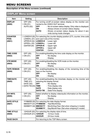
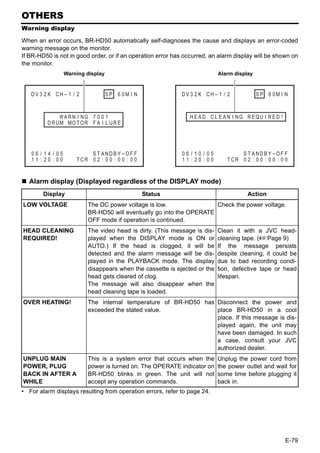
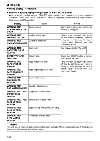
![OTHERS
Troubleshooting
Symptom Action
No power. Is the AC adapter correctly connected?
Unable to record. Is the slide of the cassette tape turned to “REC”?
Set it to “REC” if it is at the “SAVE” position.
The operation buttons of BR-HD50 Is OPERATION LOCK of the SYSTEM [2/2] Menu set to ON?
do not work. Set it to OFF if the operation buttons are to be used.
For REMOTE, select the buttons that can be operated with the
LOCAL FUNCTION Menu.
Editing cannot be controlled even To control with RS-422A, set REMOTE SEL 9P in the REMOTE
after the REMOTE/LOCAL switch [1/2] Menu screen to “ON”.
is set to REMOTE.
Noise is produced on the playback • The tape is damaged.
video. Replace the tape.
Playback sound interrupted. • The head is dirty.
Clean it with the specified head-cleaning tape. (XPage 9)
Cannot play back. Is the setting for PB TAPE FORMAT in the SYSTEM [2/2] Menu
screen something other than AUTO?
Playback is not available when this menu item does not match
the tape format.
Time codes are not correctly Is TC DUPLI.: DV in the TC/UB/CLOCK [1/2] Menu screen cor-
recorded during DV signal input. rectly set up?
Unable to turn on the power with Isn’t the REMOTE/LOCAL switch set to REMOTE when
the OPERATE button. LOCAL FUNCTION in the REMOTE [1/2] Menu screen is not
set to ALL KEYS?
SERIAL REMOTE control does not Isn’t REMOTE SEL SER in the REMOTE [1/2] Menu screen set
function. to OFF?
For SERIAL REMOTE control, set it to ON or LOC+REM.
Unable to operate BR-HD50 with • Isn’t REM SEL HDV/DV in the REMOTE [1/2] Menu screen
the IEEE1394 terminal. set to OFF? To operate with the IEEE1394 terminal, set it to
ON or LOC+REM.
• When the controlling equipment (non-linear editor, etc.) does
not recognize this unit, either reconnect the IEEE1394
cable, or reset the power to the unit.
E-81](https://image.slidesharecdn.com/br-hd50brochure-110419040454-phpapp01/85/JVC-BR-HD50-85-320.jpg)
![OTHERS
Troubleshooting (continued)
Symptom Action
Cannot record HDV signals from • Is the IEEE1394 switch on the front panel set correctly?
the IEEE1394 terminal. To record HDV signals, set this to HDV.
• Is the HD signal format set correctly?
Match the 60/50 SEL setting in the SYSTEM [2/2] Menu
screen to the input HDV signal format. (XPage 40)
Cannot record DV signals from the Is the IEEE1394 switch on the front panel set correctly?
IEEE1394 terminal. To record DV signals, set this to DV.
No HD signal is output from the Is the HD signal format set correctly?
HDMI OUT or COMPONENT OUT Match the 60/50 SEL setting in the SYSTEM [2/2] Menu screen
terminal. to the HD signal format. (XPage 40)
HDMI OUT terminal video does not Is the monitor compatible with video from the HDMI OUT termi-
display on the monitor. nal?
Check the monitor specifications.
To automatically set the HDMI OUT terminal video to the video
format for the connected equipment (monitor), set MONITOR
SELECT to HDMI[A] in the VIDEO Menu screen.
No signal is output from the • Is the IEEE1394 switch on the front panel set correctly?
IEEE1394 terminal during play- Match the IEEE1394 switch setting to the playback tape
back. recording format.
• When playing a tape recorded in HDV format, check that the
HD signal format setting is correct. (XPage 40)
E-82](https://image.slidesharecdn.com/br-hd50brochure-110419040454-phpapp01/85/JVC-BR-HD50-86-320.jpg)
![OTHERS
Checking the hour meter
This unit displays the drum usage time as the hour meter in DRUM HOUR METER in the SYSTEM [2/
2] Menu screen. Use it as a guide for regular maintenance. (XPage 8)
Use standard DV cassette tapes or mini DV cassette tapes.
MENU button R button
SET button
P button S button
TOP Menu screen
Operation
– – –MENU – – –
Set BR-HD50 to the STOP mode: SYS T EM . .
R EMO T E . .
1. Press the MENU button to display the TOP Menu screen. AUD I O . .
V I DEO . .
TC / UB / C LOCK . .
2. Press the R or P button to bring the cursor to SYSTEM. D I SPLAYSET . .
EX I T
Press SET or the S button.
The SYSTEM [1/2] Menu screen is displayed.
3. Press the R or P button to bring the cursor to NEXT PAGE.
Press SET or the S button. SYSTEM [1/2] Menu screen
The SYSTEM [2/2] Menu screen is displayed.
– – – SYS T EM [ 1 / 2 ] – – –
• The drum usage time is displayed on DRUM HOUR METER in ST L / F . ADV : DV 2ND
BACKUP REC : DV OFF
the SYSTEM [2/2] Menu screen. LONG PAUSE T I ME 3 0SEC
REC LONG P . T I ME 5M I N
4. Press the MENU button to return to the normal screen. L ONG P A U S E MOD E STBY - OFF
“ , ” KEY FUNC . VAR / RECV
R E P E A T MOD E OFF
NEXT PAGE
PAGE BACK
SYSTEM [2/2] Menu screen
– – – SYS T EM [ 2 / 2 ] – – – – – –
D C I N MOD E OPE OF F
I N D E X WR I T E I NDEX
OPERA T I ON LOCK ON
6 0 / 5 0 SEL 60
F AC TORY SE T T I NG CANCE L
DRUM HOUR ME T E R 000200
PAGE BACK
Drum usage time
E-83](https://image.slidesharecdn.com/br-hd50brochure-110419040454-phpapp01/85/JVC-BR-HD50-87-320.jpg)
![OTHERS
Specifications
General Connectors
Power requirements:DC 12 V W (from provided Video
AC adapter) [HDV]
Power consumption:DC 12 V W 26.4 W 2.2 A Video outputs
Usable tape : Standard/ mini DV cassette tape Analog component
Tape speed :18.8 mm/s Y :1.0 V (p-p), 75 Ω (BNC)
Record/play time : 276 minutes (with LA-DV276PRO PB/PR :0.7 V (p-p), 75 Ω (BNC)
tape) [DV]
63 minutes (with M-DV63PROHD Video inputs
tape) Analog composite:1.0 V (p-p), 75 Ω (BNC)
External dimension:212 mm (W) × 88 mm (H) × Analog Y/C
327 mm (D) (Excluding pro- Y :1.0 V (p-p), 75 Ω
truding parts) C :0.286 V (NTSC)/0.3 V (PAL)
Weight :Approx. 3.9 d (p-p), 75 Ω (4-pin)
(Not including AC Adapter) Video outputs
Allowable operating temperature Analog composite :1.0 V (p-p), 75 Ω (BNC)
:5°C to 40°C Analog Y/C
Allowable storage temperature Y :1.0 V (p-p), 75 Ω
:–20°C to 60°C C :0.286 V (NTSC)/0.3 V (PAL)
Allowable operating humidity (p-p), 75 Ω (4-pin)
:30% RH to 80% RH Analog component
Allowable storage humidity Y :1.0 V (p-p), 75 Ω (BNC)
:85% RH or less PB/PR :0.7 V (p-p), 75 Ω (BNC)
Video Audio
Recording format :720/24p, 720/25p, 720/30p, Audio inputs
Line :–8 dBs, 10 kΩ unbalanced
576/50p, 480/60p
(BR-HD50U/HD50E), (RCA)
480/60i (BR-HD50U), Audio outputs
Line : –8 dBs, 1 kΩ unbalanced (RCA)
576/50i (BR-HD50E)
Video format : Headphones :– ∞ to – 15 dBs, 8 Ω (Stereo
mini Jack)
[HDV]
Video signal recording format HDMI output :Type A (19-pin)
IEEE1394 interface:6-pin
:HDV720p format, 8-bit, 19.7
RS-422 interface :D-sub-9pin
Mbps
Serial remote interface:Mini jack
Compression :MPEG-2 video (profile &
level: MP@H-14) AC adapter
[DV] Input :AC 100 V – 240 V D,
Video signal recording format 50 Hz/60 Hz 1.0 A – 0.5 A
:DV format, 8-bit, 25 Mbps Output :DC 12 V W 3.5 A
Compression :DV format, 4:1:1 (NTSC)/ Accessories
4:2:0 (PAL) AC adapter (AA-G30) .................................... ×1
Audio Power cord (for BR-HD50U) ......................... ×1
[HDV] Power cord (for BR-HD50E) ......................... ×2
Audio signal recording format Ferrite core (for IEEE1394 cable) ................. ×1
:MPEG1 Audio Layer II Ferrite core (for DC cord) .............................. ×1
[DV]
Audio signal recording format
:16-bit (locked audio), 48 kHz
PCM for 2 channels or 12-bit,
32 kHz PCM for 4 channels
E-84](https://image.slidesharecdn.com/br-hd50brochure-110419040454-phpapp01/85/JVC-BR-HD50-88-320.jpg)
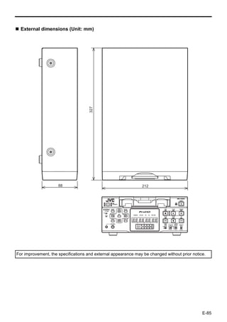


This document contains safety instructions for operating a JVC BR-HD50 HD video cassette recorder. Key points include: 1. Read all instructions carefully before operating the unit and keep the instructions handy for future reference. 2. Do not place the unit near water or in an unstable location and ensure proper ventilation to prevent overheating. 3. Refer any service needs to qualified personnel, as opening the unit yourself may expose you to electric shock. Only have repairs done by approved service technicians using proper replacement parts.


