Download as PDF, PPTX

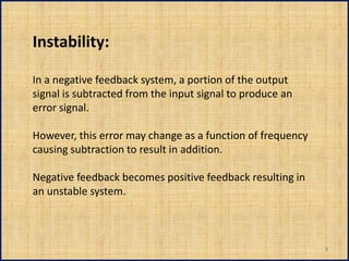
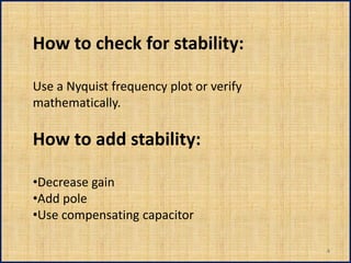

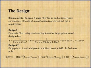
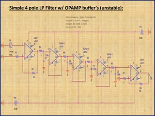
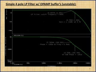

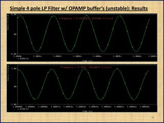

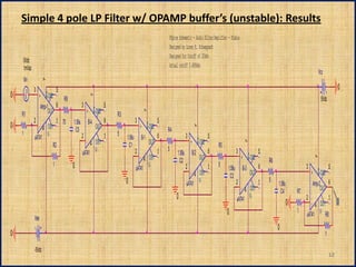
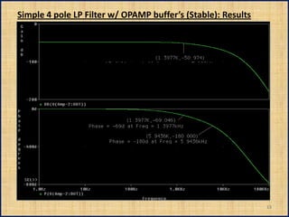
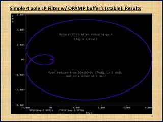


The document discusses feedback instability in electronic systems. It defines instability as negative feedback becoming positive feedback, causing the system to be unstable. The author provides equations to check for stability using a Nyquist plot or mathematically. Design considerations to add stability include decreasing gain, adding poles, and using compensating capacitors. The author then presents an original unstable 4-pole filter design and a modified stable design that decreases the gain and adds a pole.