SlideShare a Scribd company logo
1 of 73
Download to read offline
SPCC GUIDANCE FOR REGIONAL INSPECTORS 4-1
December 16, 2013
Chapter 4 Secondary Containment and
Impracticability
4.1 Introduction
The purpose of the SPCC rule is to prevent discharges of oil into navigable waters of the United States
and adjoining shorelines. One of the primary ways the rule sets out to accomplish this goal is by requiring
secondary containment. A secondary containment system provides an essential line of defense in the event of a
failure of the primary containment, such as a bulk storage container, a mobile or portable container, piping, or
oil-filled equipment. The system provides temporary containment of discharged oil until the appropriate actions
are taken to abate the source of the discharge and remove oil from areas where it has accumulated to prevent it
from reaching navigable waters or adjoining shorelines. The rule includes two categories of secondary
containment requirements:
 A general provision addresses the potential for oil discharges from all regulated parts of a
facility. The containment method, design, and capacity are determined by good engineering
practice to contain the most likely discharge of oil until cleanup occurs.
 Specific provisions address the potential of oil discharges from areas of a facility where oil is
stored or handled. The containment design, sizing, and freeboard requirements are specified by
the SPCC rule to address a major container failure.
The general secondary containment requirements are intended to address, in accordance with good
engineering practice, the most likely oil discharges from areas or containers such as mobile refuelers and other
non-transportation-related tank trucks; oil-filled operational or process equipment; (non-rack) transfer areas; or
piping. In determining the method, design, and capacity for general secondary containment, only the typical
failure mode needs to be considered.
The specific secondary containment requirements are intended to address a major container failure
(e.g., the entire contents of the container and/or compartment) associated with a bulk storage container; single
compartment of a tank car or tank truck at a loading/unloading rack; mobile/portable containers; and
production tank batteries, treatment, and separation installations (including flow-through process vessels and
produced water containers). These specific provisions (see Table 4-1 in Section 4.1.1) provide explicit
requirements for sizing, design, and freeboard.
The purpose of this chapter is to clarify the relationships among the various general and specific
secondary containment requirements of the SPCC rule, and to illustrate how these requirements apply. This
chapter also discusses the rule’s impracticability determination provision, which may be used when a facility
owner/operator cannot install secondary containment by any reasonable method. The additional requirements
that accompany an impracticability determination, the documentation needed to support such a determination,
SPCC GUIDANCE FOR REGIONAL INSPECTORS 4-2
December 16, 2013
Chapter 4: Secondary Containment and Impracticability Determination
and the role of the EPA inspector in reviewing secondary containment requirements and impracticability
determinations are also discussed.
The remainder of this chapter is organized as follows.
 Section 4.2 provides an overview of the SPCC rule’s general secondary containment provisions,
including exceptions to the requirement to provide secondary containment.
 Section 4.3 discusses the specific secondary containment requirements and the meaning of
“sufficient freeboard.”
 Section 4.4 discusses issues related to secondary containment, such as active versus passive
measures, the “sufficiently impervious” requirement, facility drainage, and man-made
structures.
 Section 4.5 describes the impracticability determination provision.
 Section 4.6 describes required measures when secondary containment is impracticable.
 Section 4.7 discusses how the impracticability determination may be used in certain
circumstances.
 Section 4.8 discusses alternative measures in the rule in lieu of secondary containment at oil
production facilities.
4.1.1 Overview of Secondary Containment Provisions
The SPCC rule includes several secondary containment provisions intended to address the various
activities or locations at a facility where oil is handled. This section differentiates among these general and
specific secondary containment provisions.
Table 4-1 lists all the secondary containment provisions of the SPCC rule for different types of facilities.
SPCC GUIDANCE FOR REGIONAL INSPECTORS 4-3
December 16, 2013
Chapter 4: Secondary Containment and Impracticability Determination
Table 4-1: Secondary containment provisions in 40 CFR part 112.
Type of Facility Secondary Containment Rule Section(s)
All Facilities General containment (areas with potential for discharge,
such as piping–including flowlines, bulk storage containers,
oil-filled operating and manufacturing equipment, and oil
equipment associated with transfer areas)
§112.7(c)
Mobile refuelers and other non-transportation-related tank
trucks.
§112.7(c)
Loading/unloading racks** §112.7(h)(1)
Qualified Oil-Filled Operational Equipment §112.7(c) or alternate measures
in §112.7(k)
Onshore Storage Bulk storage containers (except mobile refuelers and other
non-transportation-related tank trucks)
§112.8(c)(2) or §112.12(c)(2)
Mobile or portable oil containers (except mobile refuelers
and other non-transportation-related tank trucks)
§112.8(c)(11) or §112.12(c)(11)
Onshore Oil
Production
Bulk storage containers, including tank batteries,
separation, and treating facility installations (except for
flow-through process vessels and produced water
containers)
§112.9(c)(2)
Flow-through process vessels §112.9(c)(2) or
§112.7(c) and alternate
measures in §112.9(c)(5)
Flowlines and intra-facility gathering lines §112.7(c) or alternate measures
in §112.9(d)(3)
Produced water containers §112.9(c)(2) or
§112.7(c) and alternate
measures in §112.9(c)(6)
Onshore Oil Drilling
and Workover
Mobile drilling or workover equipment §112.10(c)
Offshore Oil Drilling,
Production, and
Workover
Oil drilling, production, or workover equipment §112.7(c)
** Although this requirement applies to all facilities, loading/unloading racks are generally not present at typical oil
production facilities or farms, as discussed in Section 4.7.3.
Figure 4-1 through Figure 4-4 illustrate the relationships between the secondary containment
requirements at various types of facilities. EPA inspectors should use the flowchart that corresponds to the type
of facility he or she is inspecting (see the figure description for each flowchart). The second row of each
flowchart identifies the types of containers, equipment, and activities or areas where oil is handled, with
SPCC GUIDANCE FOR REGIONAL INSPECTORS 4-4
December 16, 2013
Chapter 4: Secondary Containment and Impracticability Determination
reference to the appropriate secondary containment rule provision. The flowcharts note the use of
impracticability determinations and additional design considerations for other areas with the potential for
discharge.
Figure 4-1: Secondary containment provisions in 40 CFR part 112 related to onshore storage facilities
(§§112.7 and 112.8 or 112.12).
SPCC GUIDANCE FOR REGIONAL INSPECTORS 4-5
December 16, 2013
Chapter 4: Secondary Containment and Impracticability Determination
Figure 4-2: Secondary containment provisions in 40 CFR part 112 related to onshore oil production facilities
(§§112.7 and 112.9).
Oil production facilities do not typically have loading/unloading racks as defined in §112.2, but when oil
is transferred through a loading/unloading rack, sized secondary containment in accordance with §112.7(h)(1)
applies. Oil transfers to trucks within oil production facilities normally occur at transfer areas that are subject to
general secondary containment in accordance with §112.7(c).
SPCC GUIDANCE FOR REGIONAL INSPECTORS 4-6
December 16, 2013
Chapter 4: Secondary Containment and Impracticability Determination
Figure 4-3: Secondary containment provisions in 40 CFR part 112 related to onshore oil drilling and
workover facilities (§§112.7 and 112.10).
SPCC GUIDANCE FOR REGIONAL INSPECTORS 4-7
December 16, 2013
Chapter 4: Secondary Containment and Impracticability Determination
Figure 4-4: Secondary containment provisions in 40 CFR part 112 related to offshore oil drilling, production,
and workover facilities (§§112.7 and 112.11).P
79
4.2 General Secondary Containment Requirements
At a regulated facility, all areas and equipment with the potential for a discharge are subject to the
general secondary containment provision, §112.7(c). These may include bulk storage containers;
mobile/portable containers; mobile refuelers and other non-transportation-related tank trucks; oil production
tank batteries, treatment, and separation installations; pieces of oil-filled operational or manufacturing
equipment; loading/unloading areas (also referred to as transfer areas); and piping; and may include other areas
of a facility where oil is present. For the areas where specific (sized) secondary containment is also required (as
described in Section 4.7), this sized secondary containment fulfills the general secondary containment
requirements. The general secondary containment provision requires that these areas be designed with
appropriate containment and/or diversionary structures to prevent a discharge in quantities that may be
harmful (i.e., a discharge as described in §112.1(b)). “Appropriate containment” must be designed to address
the most likely quantity of oil that would be discharged from the primary containment system (e.g., container,
79
Onshore components associated with offshore facilities may also be subject to §§112.8 or 112.9 requirements (as applicable).
SPCC GUIDANCE FOR REGIONAL INSPECTORS 4-8
December 16, 2013
Chapter 4: Secondary Containment and Impracticability Determination
equipment), such that the discharge will not
escape secondary containment before
cleanup occurs. In determining the most likely
quantity, the facility owner/operator should
consider factors such as the typical failure
mode (e.g., overfill, fracture in container wall,
etc.), resulting oil flow rate, facility personnel
response time, and the duration of the
discharge. An example calculation for a
transfer area is included in Section 4.7.2. A
similar calculation can be applied for any area
or equipment subject to the general
secondary containment requirement (e.g., oil-
filled equipment such as transformers).
Calculations may be provided as part of the
documentation to support the adequacy of
secondary containment measures employed
at the facility, although they are not required.
Nevertheless, the Plan preparer must include
enough detail in the SPCC Plan to describe the
efficacy of the measures used to comply with
the general secondary containment
requirements in §112.7(c).
Section 112.7(c) lists several methods
of providing secondary containment, which
are described in Table 4-2. These methods are
examples only; other containment methods
may be used, consistent with good
engineering practice. For example, a facility
could use an oil/water separator, combined
with a drainage system, to collect and retain discharges of oil within the facility. PE certification (or self-
certification, in the case of qualified facilities) of the SPCC Plan includes verification that the selected secondary
containment methods for the facility are appropriate and follow good engineering practice.
§112.7(c)
Provide appropriate containment and/or diversionary structures
or equipment to prevent a discharge as described in §112.1(b)
except as provided in paragraph (k) of this section for qualified oil-
filled operational equipment, and except as provided in
§112.9(d)(3) for flowlines and intra-facility gathering lines at an oil
production facility. The entire containment system, including walls
and floor, must be capable of containing oil and must be
constructed so that any discharge from a primary containment
system, such as a tank or pipe, will not escape the containment
system before cleanup occurs. In determining the method, design,
and capacity for secondary containment, you need only to address
the typical failure mode, and the most likely quantity of oil that
would be discharged. Secondary containment may be either active
or passive in design. At a minimum, you must use one of the
following prevention systems or its equivalent:
(1) For onshore facilities:
(i) Dikes, berms, or retaining walls sufficiently impervious to
contain oil;
(ii) Curbing or drip pans;
(iii) Sumps and collection systems;
(iv) Culverting, gutters, or other drainage systems;
(v) Weirs, booms, or other barriers;
(vi) Spill diversion ponds;
(vii) Retention ponds; or
(viii) Sorbent materials.
(2) For offshore facilities:
(i) Curbing or drip pans; or
(ii) Sumps and collection systems.
Note: The above text is an excerpt of the SPCC rule. Refer to 40 CFR part 112
for the full text of the rule.
SPCC GUIDANCE FOR REGIONAL INSPECTORS 4-9
December 16, 2013
Chapter 4: Secondary Containment and Impracticability Determination
Table 4-2: Example methods of secondary containment listed in §112.7(c).
Secondary
Containment Method
Description of Examples
Dikes, berms, or
retaining walls
sufficiently impervious
to contain oil
Types of permanent engineered barriers, such as raised earth embankments or concrete
containment walls, designed to hold oil. Normally used in areas with potential for large
discharges, such as single or multiple aboveground storage tanks and certain piping.
Temporary dikes and berms may be constructed after a discharge is discovered as an active
containment measure (or a countermeasure) so long as they can be implemented in time to
prevent the spilled oil from reaching surface waters. Please see Section 4.4.1, Passive versus
Active Measures of Secondary Containment.
Curbing Typically consists of a permanent reinforced concrete or an asphalt apron surrounded by a
concrete curb. Can also be of a uniform, rectangular cross-section or combined with
mountable curb sections to allow access to loading/unloading vehicles and materials handling
equipment. Can be used where only small spills are expected and also used to direct spills to
drains or catchment areas. Temporary curbing may be constructed after a discharge is
discovered as an active containment measure (or a countermeasure) so long as it can be
implemented in time to prevent the spilled oil from reaching surface waters. Please see
Section 4.4.1, Passive versus Active Measures of Secondary Containment.
Culverting, gutters, or
other drainage systems
Types of permanent drainage systems designed to direct spills to remote containment or
treatment areas. Ideal for situations where spill containment structures cannot or should not
be located immediately adjacent to the potential spill source.
Weirs Dam-like structures with a notch through which oil may flow to be collected. Generally used
in combination with skimmers to remove oil from the surface of water.
Booms Form a continuous barrier placed as a precautionary measure to contain/collect oil. Typically
used for the containment, exclusion, or deflection of oil floating on water, and is usually
associated with an oil spill contingency or facility response plan to address oil spills that have
reached surface waters. Beach booms are designed to work in shallow or tidal areas.
Sorbent-filled booms can be used for land-based spills. There are very limited applications for
use of booms for land-based containment of discharged oil.
Barriers Spill mats, storm drain covers, and dams used to block or prevent the flow of oil. Temporary
barriers may be put in place prior to a discharge or after a discharge is discovered. These are
all considered effective active containment measures (or countermeasures) as long as they
can be implemented in time to prevent the spilled oil from reaching navigable waters and
adjoining shorelines. Please see Section 4.4.1, Passive versus Active Measures of Secondary
Containment.
Discharge as described in §112.1(b) is a discharge in quantities that may be harmful, as described in part 110 of this
chapter [40 CFR part 110], into or upon the navigable waters of the United States or adjoining shorelines, or into or
upon the waters of the contiguous zone, or in connection with activities under the Outer Continental Shelf Lands Act or
the Deepwater Port Act of 1974, or that may affect natural resources belonging to, appertaining to, or under the
exclusive management authority of the United States (including resources under the Magnuson Fishery Conservation
and Management Act).
Note: The above text is an excerpt of the SPCC rule. Refer to 40 CFR part 112 for the full text of the rule.
SPCC GUIDANCE FOR REGIONAL INSPECTORS 4-10
December 16, 2013
Chapter 4: Secondary Containment and Impracticability Determination
Secondary
Containment Method
Description of Examples
Spill diversion ponds
and retention ponds
Designed for long-term or permanent containment of storm water, but also capable of
capturing and holding oil or runoff and preventing it from entering surface water bodies.
Temporary spill diversion ponds and retention ponds may be constructed after a discharge is
discovered as an active containment measure (or countermeasure) as long as they can be
implemented in time to prevent the spilled oil from reaching navigable waters and adjoining
shorelines. There are very limited applications for use of temporary spill diversion and
retention ponds for land-based containment of discharged oil due to the timely availability of
the appropriate excavation equipment required to rapidly construct the ponds. Please see
Section 4.4.1, Passive versus Active Measures of Secondary Containment.
Sorbent materials Insoluble materials or mixtures of materials (packaged in forms such as spill pads, pillows,
socks, and mats) used to recover liquids through the mechanisms of absorption, adsorption,
or both. Materials include clay, vermiculite, diatomaceous earth, and man-made materials.
Used to isolate and contain small drips or leaks until the source of the leak is repaired.
Commonly used with material handling equipment, such as valves and pumps. Also used as
an active containment measure (or countermeasure) to contain and collect small-volume
discharges before they reach waterways. Proper use of these materials may require a
properly equipped and trained spill response team specifically trained to contain an oil
discharge prior to reaching navigable waters or adjoining shorelines Please see Section 4.4.1,
Passive versus Active Measures of Secondary Containment.
Drip pans Used to isolate and contain small drips or leaks until the source of the leak is repaired. Drip
pans are commonly used with product dispensing containers (usually drums), when
uncoupling hoses during bulk transfer operations, and for pumps, valves, and fittings.
Sumps and collection
systems
A permanent pit or reservoir and its associated troughs/trenches that collect oil.
The general secondary containment provision applies to all areas of a facility that have a potential to
cause an oil discharge. However, the provision allows for alternative measures in the SPCC Plan for:
 Qualified oil-filled operational equipment; and
 Flowlines and intra-facility gathering lines
These alternative measures are further described below.
SPCC GUIDANCE FOR REGIONAL INSPECTORS 4-11
December 16, 2013
Chapter 4: Secondary Containment and Impracticability Determination
4.2.1 Alternative Measures for General Secondary Containment Requirement: Qualified
Oil-Filled Operational Equipment
Providing adequate secondary containment
for oil-filled operational equipment is often
impracticable, therefore, the SPCC rule provides an
optional alternative to the general secondary
containment requirements for oil-filled operational
equipment that meets qualifying criterion in
§112.7(k) (commonly referred to as “qualified oil-
filled operational equipment”).
Oil-filled operational equipment, as defined
in §112.2, is equipment that includes an oil storage
container (or multiple containers) in which the oil
present is used solely to support the function of the
apparatus or the device. For more information on oil-
filled equipment, refer to Chapter 2: SPCC Rule
Applicability.
§112.7(k)
Qualified Oil-filled Operational Equipment. The owner or operator of a facility with oil-filled operational equipment
that meets the qualification criteria in paragraph (k)(1) of this sub-section may choose to implement for this qualified
oil-filled operational equipment the alternate requirements as described in paragraph (k)(2) of this sub-section in lieu
of general secondary containment required in paragraph (c) of this section.
(1) Qualification Criteria—Reportable Discharge History: The owner or operator of a facility that has had no single
discharge as described in § 112.1(b) from any oil-filled operational equipment exceeding 1,000 U.S. gallons or no two
discharges as described in § 112.1(b) from any oil-filled operational equipment each exceeding 42 U.S. gallons within
any twelve month period in the three years prior to the SPCC Plan certification date, or since becoming subject to this
part if the facility has been in operation for less than three years (other than oil discharges as described in § 112.1(b)
that are the result of natural disasters, acts of war or terrorism)
(2) Alternative Requirements to General Secondary Containment. If secondary containment is not provided for qualified
oil-filled operational equipment pursuant to paragraph (c) of this section, the owner or operator of a facility with
qualified oil-filled operational equipment must:
(i) Establish and document the facility procedures for inspections or a monitoring program to detect equipment failure
and/or a discharge; and
(ii) Unless you have submitted a response plan under §112.20, provide in your Plan the following:
(A) An oil spill contingency plan following the provisions of part 109 of this chapter.
(B) A written commitment of manpower, equipment, and materials required to expeditiously control and
remove any quantity of oil discharged that may be harmful.
Note: The above text is an excerpt of the SPCC rule. Refer to 40 CFR part 112 for the full text of the rule.
§112.2
Oil-filled operational equipment means equipment that
includes an oil storage container (or multiple containers)
in which the oil is present solely to support the function
of the apparatus or the device. Oil-filled operational
equipment is not considered a bulk storage container,
and does not include oil-filled manufacturing equipment
(flow-through process). Examples of oil-filled operational
equipment include, but are not limited to, hydraulic
systems, lubricating systems (e.g., those for pumps,
compressors and other rotating equipment, including
pumpjack lubrication systems), gear boxes, machining
coolant systems, heat transfer systems, transformers,
circuit breakers, electrical switches, and other systems
containing oil solely to enable the operation of the
device.
Note: The above text is an excerpt of the SPCC rule. Refer to 40 CFR
part 112 for the full text of the rule.
SPCC GUIDANCE FOR REGIONAL INSPECTORS 4-12
December 16, 2013
Chapter 4: Secondary Containment and Impracticability Determination
Determining Eligibility for Alternative Measures for Oil-Filled Operational Equipment
The facility owner/operator determines if he is eligible to use the alternative measures in §112.7(k) by
considering the reportable discharge history from any oil-filled operational equipment at the facility. Table 4-3
identifies the criterion for determining if the facility has qualified oil-filled operational equipment.
Table 4-3: Reportable discharge history criterion for oil-filled operational equipment.
You must answer no to the following to be eligible for alternative measures in §112.7(k):
In the three years before the SPCC Plan is certified, has the facility had any discharges to navigable waters or adjoining
shorelines from oil-filled operational equipment as described below:
A single discharge of oil greater than 1,000 gallons? Yes or No
Two discharges of oil each greater than 42 gallons within any 12-month period? Yes or No
When considering the above questions, the owner/operator does not need to include discharges that
are the result of natural disasters, acts of war, or terrorism. Additionally, when determining the applicability of
this SPCC reporting requirement, the gallon amount(s) specified (either 1,000 or 42) refers to the amount of oil
that actually reaches navigable waters or adjoining shorelines, not the total amount of oil spilled. EPA considers
the entire volume of the discharge to be oil for the purposes of these reporting requirements.
Let’s consider the following examples:
UExample 1:U A facility has one discharge from oil-filled operational equipment over the past three years in
which 1,500 gallons of oil discharged onto the ground but only 20 gallons reached navigable waters or adjoining
shorelines (causing a sheen and reportable to the NRC).
You must answer no to the following to be eligible for alternative measures in §112.7(k):
In the three years before the SPCC Plan is certified, has the facility had any discharges to navigable waters or adjoining
shorelines from oil-filled operational equipment as described below:
A single discharge of oil greater than 1,000 gallons? No
Two discharges of oil each greater than 42 gallons within any 12-month period? No
Does the facility have qualified oil-filled operational equipment? Yes. The facility has qualified oil-filled
operational equipment because there was only one reportable oil discharge from oil-filled operational
equipment and the amount discharged to navigable waters (20 gallons) was less than 1,000 gallons (i.e., they
met the reportable discharge history criterion).
SPCC GUIDANCE FOR REGIONAL INSPECTORS 4-13
December 16, 2013
Chapter 4: Secondary Containment and Impracticability Determination
UExample 2:U A facility has one 1,500-gallon discharge from oil-filled operational equipment to navigable
waters.
You must answer no to the following to be eligible for alternative measures in §112.7(k):
In the three years before the SPCC Plan is certified, has the facility had any discharges to navigable waters or adjoining
shorelines from oil-filled operational equipment as described below:
A single discharge of oil greater than 1,000 gallons? Yes
Two discharges of oil each greater than 42 gallons within any 12-month period? No
Does the facility have qualified oil-filled operational equipment? No. In this example, the oil discharge to
navigable waters was larger than 1,000 gallons and therefore the facility does not qualify for alternative
measures.
UExample 3:U A 2,000-gallon oil discharge to navigable waters occurs while unloading a vehicle into a bulk
storage container.
You must answer no to the following to be eligible for alternative measures in §112.7(k):
In the three years before the SPCC Plan is certified, has the facility had any discharges to navigable waters or adjoining
shorelines from oil-filled operational equipment as described below:
A single discharge of oil greater than 1,000 gallons? No
Two discharges of oil each greater than 42 gallons within any 12-month period? No
Does the facility have qualified oil-filled operational equipment? Yes. The facility has qualified oil-filled
operational equipment because the oil discharge did not originate from oil-filled operational equipment and
therefore is not considered when determining eligibility of the facility to use alternative measures for qualified
oil-filled operational equipment.
Alternative Measures
If an owner or operator uses alternative measures in lieu of meeting the secondary containment
requirements for qualified oil-filled operational equipment., he or she is required to establish and document an
inspection or monitoring program for qualified oil-filled operational equipment to detect equipment failure
and/or a discharge. Additionally, the owner/operator must prepare an oil spill contingency plan and provide a
written commitment of manpower, equipment, and materials required to expeditiously control and remove any
quantity of oil discharged that may be harmful (unless the facility has submitted a Facility Response Plan.) The
advantage of the §112.7(k) alternative to the general secondary containment requirements is that the facility
owner/operator is not required to prepare an impracticability determination for the qualified oil-filled
operational equipment (impracticability determinations are discussed in Section 4.5 of this chapter). Note that
the use of alternative measures is optional for qualified oil-filled operational equipment; the owner/operator
can instead provide secondary containment or may prepare an impracticability determination.
SPCC GUIDANCE FOR REGIONAL INSPECTORS 4-14
December 16, 2013
Chapter 4: Secondary Containment and Impracticability Determination
For facility owners and operators that rely on contingency planning for qualified oil-filled operational
equipment in lieu of secondary containment, the discovery of a discharge by inspection or monitoring is critical
for effective and timely implementation of the contingency plan. An inspection or monitoring program ensures
that facility personnel are alerted quickly of equipment failures and/or discharges. The SPCC Plan must describe
the inspection or monitoring program and the owner or operator must keep a record of inspections and tests,
signed by the appropriate supervisor or inspector, for a period of three years in accordance with §112.7(e).
Qualified Oil-Filled Operational Equipment and Qualified Facilities Overlap
Some facilities may meet the criteria for qualified facilities as provided in §112.3(g) and have qualified
oil-filled operational equipment on-site. Owners and operators of such facilities can use the alternative
measures for oil-filled operational equipment described in §112.7(k) and self-certify the SPCC Plan. The owner or
operator can choose to develop an oil spill contingency plan, provide a written commitment of manpower,
equipment and materials and implement an inspection or monitoring
program as an alternative to secondary containment for qualified oil-
filled operational equipment. Since no impracticability determination
is necessary for qualified oil-filled operational equipment, the owner
or operator can self-certify his/her SPCC Plan and is not required to
have a PE develop and certify the contingency plan for the qualified
oil-filled operational equipment. The responsibility of preparing a
contingency plan and identifying the necessary equipment, materials
and manpower to implement the contingency plan would fall on the
owner or operator of the qualified facility. For more information on
qualified facilities, visit the EPA website at
4TUhttp://www.epa.gov/oem/content/spcc/spcc_qf.htm.
Oil-Filled Manufacturing Equipment is not Oil-Filled Operational Equipment
The definition of oil-filled operational equipment does not include oil-filled manufacturing equipment
(flow-through process). Oil-filled manufacturing equipment is inherently more complicated than oil-filled
operational equipment because it typically involves a flow-through process and is commonly interconnected
through piping. For example, oil-filled manufacturing equipment may receive a continuous supply of oil, in
contrast to the static capacity of other, non-flow-through oil-filled equipment. Examples of oil-filled
manufacturing equipment include, but are not limited to, process vessels, conveyances such as piping associated
with a process, and equipment used in the alteration, processing or refining of crude oil and other non-
petroleum oils, including animal fats and vegetable oils (71 FR 77276, December 26, 2006).
Tip – Generator sets
One commonly asked question is
whether generator sets are considered
oil-filled operational equipment.
No. Generator sets (gen sets) are a
combination of oil-filled operational
equipment and a bulk storage
container. Lubrication systems on gen
sets may be oil-filled operational
equipment, but bulk storage tanks
providing fuel for the generator
typically are not oil-filled operational
equipment.
SPCC GUIDANCE FOR REGIONAL INSPECTORS 4-15
December 16, 2013
Chapter 4: Secondary Containment and Impracticability Determination
4.2.2 Alternative Measures for General Secondary Containment Requirement: Flowlines
and Intra-facility Gathering Lines
“Flowlines” are typically found at oil production facilities. They are piping that transfer crude oil and
well fluids from the wellhead to the tank battery where separation and treatment equipment are typically
located. Flowlines may also connect a tank battery to an injection well. Depending on the size of the oil field,
flowlines may range in diameter and run from hundreds of
feet to miles between the wellheads and the tank
batteries or primary separation operations.
The term ‘‘gathering lines’’ refers to piping or
pipelines that transfer crude oil product between tank
batteries, within or between facilities. Gathering lines
often originate from an oil production facility’s lease
automatic custody transfer (LACT) unit, which transfers oil
to other facilities involved in gathering, refining or pipeline
transportation operations. EPA considers gathering lines
subject to EPA’s jurisdiction if they are located within the
boundaries of an otherwise regulated SPCC/FRP facility
(that is, intra-facility gathering lines) (73 FR 74274,
December 5, 2008). See Section 2.5.8 for a more detailed
description of flowlines and intra-facility gathering lines,
and the SPCC rule’s applicability to each; note that intra-facility gathering lines subject to DOT requirements at
49 CFR parts 192 or 195 are exempt from the SPCC rule entirely.
Secondary containment is, in many cases, impracticable for flowlines and intra-facility gathering lines.
For example, an oil production facility in a remote area may have many miles of flowlines and gathering lines,
around which it would not be practicable to build permanent containment structures. It may not be possible to
install secondary containment around flowlines running across a farmer’s or rancher’s fields since berms may
become severe erosional features and can impede access to the fields by farm/ranch tractors and other
equipment. Similarly, it may be impracticable to construct secondary containment around flowlines that run
along a fence or county road due to space limitations or intrusions into a county’s property or right-of-way. At
unattended facilities, active secondary containment methods are not effective in meeting secondary
containment requirements because there is limited capability to detect a discharge and deploy active measures
in a timely fashion.
Therefore, §112.9(d)(3) provides an optional alternative to the general secondary containment
requirements for flowlines and intra-facility gathering lines that are subject to the SPCC rule. In lieu of secondary
containment, the facility owner or operator may implement an oil spill contingency plan in accordance with 40
CFR part 109 (Criteria for State, Local and Regional Oil Removal Contingency Plans) and have a written
commitment of manpower, equipment, and materials required to expeditiously control and remove any
quantity of oil discharged that may be harmful. These requirements are the same as those in §112.7(d) of the
§112.9(d)(3)
For flowlines and intra-facility gathering lines that
are not provided with secondary containment in
accordance with §112.7(c), unless you have
submitted a response plan under §112.20, provide
in your Plan the following:
(i) An oil spill contingency plan following the
provisions of part 109 of this chapter.
(ii) A written commitment of manpower,
equipment, and materials required to expeditiously
control and remove any quantity of oil discharged
that might be harmful.
Note: The above text is an excerpt of the SPCC rule. Refer to
40 CFR part 112 for the full text of the rule.
SPCC GUIDANCE FOR REGIONAL INSPECTORS 4-16
December 16, 2013
Chapter 4: Secondary Containment and Impracticability Determination
rule, however, the Plan does not need to include an impracticability determination for each flowline and intra-
facility gathering line.
The contingency plan required when secondary containment is not practicable for flowlines and intra-
facility gathering lines should rely on strong maintenance, corrosion protection, testing, recordkeeping, and
inspection procedures to prevent and quickly detect discharges from such lines. It should also ensure quick
availability and deployment of response equipment. An effective flowline maintenance program is necessary to
detect a discharge in a timely manner so that the oil discharge response operations described in the contingency
plan may be implemented effectively.
Additionally, eliminating the requirement for secondary containment means that more prescriptive
requirements are needed for discharge prevention to ensure the integrity of the primary containment of the
pipe itself. The SPCC rule requires a performance-based program of flowline and intra-facility gathering line
maintenance, in accordance with §112.9(d)(4), that addresses the facility owner or operator’s procedures and
must be documented in their SPCC Plan. See Section 3.3.5 and Chapter 7: Inspection, Evaluation, and Testing
(Section 7.2.12) for more information.
The complexity or simplicity of a facility’s contingency plan is subject to good engineering practice as
determined by the Plan certifier. EPA developed a model contingency plan (see Appendix F of this guidance).
This model contingency plan is intended as an example and inspectors should only use it for this purpose.
4.3 Specific (Sized) Secondary Containment Requirements
While all parts of a regulated facility with potential for a discharge are, at a minimum, subject to the
general secondary containment requirements of §112.7(c),P
80
P areas where certain types of containers, activities,
or equipment are located may be subject to additional, more stringent containment requirements, including
specifications for minimum capacity (see Table 4-1.) The SPCC rule specifies a required minimum size for
secondary containment for the following areas:
 Loading/unloading racks;
 Bulk storage containers including mobile or portable containers (does not apply to mobile
refuelers or other non-transportation-related tank trucks); and
 Production facility bulk storage containers, including tank batteries, separation, and treating
equipment (e.g., produced water tanks).
The applicable requirements for each of these types of containers or equipment are discussed in more
detail in Section 4.7 of this chapter. In general, provisions for specific secondary containment require that the
80
Note that the rule includes alternative provisions for certain equipment, in lieu of the general secondary containment
requirements of §112.7(c).
SPCC GUIDANCE FOR REGIONAL INSPECTORS 4-17
December 16, 2013
Chapter 4: Secondary Containment and Impracticability Determination
chosen containment method be sized to contain the largest single oil compartment or container plus “sufficient
freeboard” to contain precipitation,P
81
P as discussed in Section 4.3.2 below.
EPA inspectors should note that the “largest single compartment” may consist of several containers that
are permanently manifolded together. Permanently manifolded tanks are tanks that are designed, installed, or
operated in such a manner that the multiple containers function as a single storage unit (67 FR 47122, July 17,
2002). Accordingly, the total capacity of manifolded containers is the design capacity standard for the sized
secondary containment provisions (plus freeboard in certain cases).
4.3.1 Role of the EPA Inspector in Evaluating Secondary Containment Methods
The EPA inspector should evaluate whether the secondary containment system is adequate for the
facility, and whether it is maintained to contain oil discharges to navigable waters or adjoining shorelines. This
evaluation may include reviewing inspection reports and maintenance records. Some items that the inspector
should look for include:
For a dike, berm, or other engineered secondary containment system:
 Capacity of the system to contain oil as
determined in accordance with good
engineering practice and the
requirements of the rule;
 Cracks in containment system materials
(e.g., concrete, liners, coatings, earthen
materials);
 Discoloration;
 Presence of spilled or leaked material
(standing liquid);
 Corrosion of the system;
 Erosion of the system;
 Operational status of drain valves or other
drainage controls;
 Dike or berm permeability;
 Presence of debris;
 Level of precipitation in diked area and
available capacity versus design capacity;
 Location/status of pipes, inlets, and
drainage around and beneath containers;
 Excessive vegetation that may inhibit
visual inspection and assessment of berm
integrity;
 Large-rooted plants (e.g., shrubs, cacti,
trees) that could affect the berm integrity;
 Holes or penetrations to the containment
system created by burrowing animals; and
 Drainage records for rainwater discharges
from containment areas.
81
Does not apply to the loading and unloading rack secondary containment requirements.
SPCC GUIDANCE FOR REGIONAL INSPECTORS 4-18
December 16, 2013
Chapter 4: Secondary Containment and Impracticability Determination
For retention and drainage ponds:
 Capacity of the system to contain oil as
determined in accordance with good
engineering practice and the rule
requirements;
 Erosion of the system;
 Discoloration;
 Design capacity versus available capacity;
 Presence of spilled or leaked liquid;
 Presence of debris;
 Cracks in containment system materials
(e.g., concrete, liners, coatings, earthen
materials);
 Stressed vegetation;
 Evidence of water seeps from the system;
and
 Operational status of drain valves or other
drainage controls.
While the rule does not require that secondary containment calculations be kept in the Plan, EPA
strongly recommends that the facility owner or operator maintain the calculations such that if questions arise
during an inspection, the calculations which serve as the basis for the capacity of the secondary containment
system will be readily available for review by the EPA inspector. Industry guidance also recommends that facility
owners or operators include any secondary containment capacity calculations and/ or design standards with the
Plan. API Bulletin D16, ‘‘Suggested Procedure for Development of a Spill Prevention Control and
Countermeasure Plan,’’ contains example calculations to which inspectors may refer (see Exhibit E of
‘‘Suggested Procedure for Development of Spill Prevention Control and Countermeasure Plans,’’ API Bulletin
D16. Fifth Edition, April 2011).
Examples and blank worksheets are available in Appendix H of this guidance. These documents were
developed to help qualified facility owner/operators to calculate secondary containment volume.P
82
P These
worksheets address four specific scenarios and may not be valid for every facility:
 Single Vertical Cylindrical Tank Inside a Rectangular or Square Dike or Berm
 Multiple Horizontal Cylindrical Tanks Inside a Rectangular or Square Dike or Berm
 Rectangular or Square Remote Impoundment Structure
 Constructing New Secondary Containment
82
Disclaimer: Please note that these are simplified calculations for qualified facilities that assume: 1) the secondary containment
is designed with a flat floor; 2) the wall height is equal for all four walls; and 3) the corners of the secondary containment
system are 90 degrees. Additionally, the calculations do not include displacement for support structures or foundations. For
Professional Engineer (PE) certified Plans, the PE may need to account for site-specific conditions associated with the secondary
containment structure which may require modifications to these sample calculations to ensure good engineering practice.
SPCC GUIDANCE FOR REGIONAL INSPECTORS 4-19
December 16, 2013
Chapter 4: Secondary Containment and Impracticability Determination
4.3.2 Sufficient Freeboard
The SPCC rule does not specifically define the term “sufficient freeboard,” nor does it describe how to
calculate this volume. The 1991 proposed amendment to the SPCC rule recommended the use of industry
standards and data on 25-year storm events to determine the appropriate freeboard capacity. Numerous
commenters on the 1991 proposal questioned the 25-year storm event recommendation and suggested
alternatives, such as using 110 percent of storage tank capacity or using other characteristic storm events. EPA
addressed these comments in the preamble to the 2002 amendments to the rule:
We believe that the proper standard of “sufficient freeboard” to contain precipitation is that amount
necessary to contain precipitation from a 25-year, 24-hour storm event. That standard allows flexibility
for varying climatic conditions. It is also the standard required for certain tank systems storing or
treating hazardous waste. (67 FR 47117, July 17, 2002)
However, the SPCC rule did not set this standard as a requirement for freeboard capacity. Therefore, the
use of precipitation data from a 25-year, 24-hour storm event is not enforceable as a standard for containment
freeboard. In the 2002 preamble, EPA further stated:
While we believe that the 25-year, 24-hour storm event standard is appropriate for most facilities and
protective of the environment, we are not making it a rule standard because of the difficulty and expense
for some facilities of securing recent information concerning such storm events at this time. (67 FR
47117, July 17, 2002)
Ultimately, EPA determined that, for freeboard, “the proper method of secondary containment is a
matter of engineering practice so [EPA does] not prescribe here any particular method” (67 FR 47101, July 17,
2002). However, where data are available, the facility owner/operator (and/or certifying PE) may want to
consider the appropriateness of the 25-year, 24-hour storm event precipitation design criteria for containment
freeboard.
A “110 percent of storage tank capacity” rule of thumb may be an acceptable design criterion in many
situations, and aboveground storage tank regulations in many states require secondary containment to be sized
to contain at least 110 percent of the volume of the largest tank. However, in some situations, 110 percent of
storage tank capacity may not provide enough volume to contain precipitation from storm events. Some states
require that facilities consider storm events when designing secondary containment structures, and in certain
cases these requirements translate to more stringent sizing criteria than the 110 percent rule of thumb.
Other important factors may be considered in determining necessary secondary containment capacity.
According to practices recommended by industry groups such as the American Petroleum Institute (API), these
factors include:
 Local precipitation conditions (rainfall and/or snowfall);
 Height of the existing dike wall;
SPCC GUIDANCE FOR REGIONAL INSPECTORS 4-20
December 16, 2013
Chapter 4: Secondary Containment and Impracticability Determination
 Size of tank/container;
 Safety considerations; and
 Frequency of dike drainage and inspection.
The following examples (Figure 4-5 and Figure 4-6) present secondary containment size calculations for
hypothetical oil storage areas. The certifying PE (or owner/operator, in the case of qualified facilities)
determines what volume constitutes sufficient freeboard for precipitation for secondary containment and
should document in the Plan how the determination was made.
SPCC GUIDANCE FOR REGIONAL INSPECTORS 4-21
December 16, 2013
Chapter 4: Secondary Containment and Impracticability Determination
Figure 4-5: Sample calculation of containment size, using two design criteria.
The following example compares two different design criteria: one based on the volume of the tank and one based on precipitation.
Scenario:
A 20,000-gallon horizontal tank is placed within an engineered secondary containment structure, such as a concrete dike. The tank is
35 feet long by 10 feet in diameter. The secondary containment area provides a 5-foot buffer on all sides (i.e., dike dimensions are 45
feet x 20 feet.
Given the dike footprint, we want to determine the wall height necessary to provide sufficient freeboard for precipitation, based on
(1) the tank storage capacity; (2) actual precipitation data. Several storm events in the recent past caused precipitation in amounts
between 3.6 and 4.0 inches at this location, although greater amounts have also been reported in the past. Note: The factor for
converting cubic feet to gallons is 7.48 gallons/ft
3
.
1. Calculation of secondary containment capacity, based on a design criterion of 110% of tank storage capacity:
Containment surface area = 45 ft x 20 ft = 900 ft
2
Tank volume, based on 100% of tank capacity = 20,000 gallons
Tank volume, in cubic feet = 20,000 gallons / 7.48 gallons/ft
3
= 2,674 ft
3
Wall height that would contain the tank’s volume = 2,674 ft
3
/ 900 ft
2
= 2.97 ft
Containment capacity with freeboard, based on 110% of tank capacity = 22,000 gallons
Containment capacity, in cubic feet = 22,000 gallons / 7.48 gallons/ft
3
= 2,941 ft
3
Wall height equivalent to 110% of storage capacity = 2,941 ft
3
/ 900 ft
2
= 3.27 feet
Height of freeboard = 3.27 ft - 2.97 ft = 0.3 ft = 3.6 inches
Therefore, a dike design based on a criterion of 110% of tank capacity provides a dike wall height of 3.27 feet.
2. Calculation of secondary containment capacity, based on rainfall criterion:
After a review of historical precipitation data for the vicinity of the facility, the PE determined that a 4.5 inch rain event is the most
reasonable design criterion for this diked area.
Containment surface area = 45 ft x 20 ft = 900 ft
2
Tank volume, based on 100% of tank capacity = 20,000 gallons
Tank volume, in cubic feet = 20,000 gallons / 7.48 gallons/ft
3
= 2,674 ft
3
Wall height that would contain the tank’s volume = 2,674 ft
3
/ 900 ft
2
= 2.97 ft
The height of the dike would need to be 3.35 feet (2.97 ft + 4.5 in).
Therefore, a dike design based on a 4.5 inch rain event provides a dike wall height of 3.35 feet, or almost 1 inch higher than calculated
using the 110% criterion.
Conclusion:
As noted from the comparison of the two design criteria illustrated above, the dike heights are similar although not exactly the same.
The adequacy of the secondary containment freeboard is ultimately an engineering determination made by the PE and certified in the
Plan.
SPCC GUIDANCE FOR REGIONAL INSPECTORS 4-22
December 16, 2013
Chapter 4: Secondary Containment and Impracticability Determination
Figure 4-6: Sample secondary containment calculations, for multiple tanks in a containment area.
The EPA inspector has questioned the adequacy of the secondary containment based on the following scenario and wants to verify
how much precipitation the dike area can hold and compare it to available precipitation data to determine if 112% is an adequate
design criterion for this facility.
Scenario:
A 60 ft x 36 ft concrete dike surrounds one 20,000-gallon horizontal tank (10 ft diameter and 35 ft length) and two 10,000-gallon
vertical tanks (each 10 ft diameter and 15 ft height). The dike walls are 18 inches (1.5 feet) tall. The SPCC Plan states that secondary
containment is designed to hold 112% of the volume of the largest container.
Notes:
 The factor for converting gallons to cubic feet is 7.48 gallons/ft
3
.
 The volume displaced by a cylindrical vertical tank is the tank volume within the containment structure and is equal to the
tank footprint multiplied by height of the concrete dike. The tank footprint is equal to  D
2
/4, where D is the tank diameter.
1. Calculate total dike capacity:
Total capacity of the concrete dike = length x width x height = 60 ft x 36 ft x 1.5 ft = 3,240 ft
3
= 24,235 gallons
2. Calculate net dike capacity, considering displacement from other tanks within the dike:
The total capacity of the concrete dike is reduced by the volume displaced by other tanks inside the containment structure.
The displacement is:
= number of tanks x footprint x height of dike wall = 2  (10 ft)
2
/4 x 1.5 ft = 235.6 ft
3
= 1,762 gallons
The net dike capacity, i.e., the volume that would be available in the event of a failure of the largest tank within the dike, is:
= Total volume - tank displacement = 24,235 - 1,762 = 22,473 gallons = 3,004 ft
3
3. Calculate the amount of available freeboard provided by the dike, given the net dike capacity:
The available freeboard volume is:
= Net dike capacity - volume of largest tank within the dike
= 22,473 - 20,000 = 2,473 gallons = 331 ft
3
This is equivalent, expressed in terms of the capacity of the largest tank, to:
= Net dike capacity/volume of largest tank within the dike
= 22,473 / 20,000 = 112%
This available freeboard volume provides a freeboard height:
= Available freeboard volume / dike surface area
= 331 ft
3
/ (60 ft x 36 ft) = 0.15 ft ≈1.8 in
Therefore, this dike provides sufficient freeboard for 1.8 inches of precipitation.
Conclusion:
The EPA inspector should review the Plan and/or inquire about the precipitation event considered in determining that sufficient
freeboard for precipitation is provided. The adequacy of the secondary containment freeboard is ultimately an engineering
determination made by the PE and is certified in the Plan. This example serves only as a guide on doing the calculations for certain
circumstances in which the inspector has concerns with the freeboard volume associated with the secondary containment design.
SPCC GUIDANCE FOR REGIONAL INSPECTORS 4-23
December 16, 2013
Chapter 4: Secondary Containment and Impracticability Determination
4.3.3 Role of the EPA Inspector in Evaluating Sufficient Freeboard
When reviewing an SPCC Plan, the EPA inspector should evaluate whether the size of secondary
containment is adequate to meet the freeboard requirement. When examining the secondary containment
measures for bulk storage containers, mobile or portable oil containers, and oil production facility bulk storage
containers, the inspector should ensure that the Plan documents that the secondary containment can hold the
entire capacity of the largest single container, plus sufficient freeboard to contain precipitation. Whatever
method is used to calculate the amount of freeboard that is “sufficient” for the facility and container
configuration should be documented in the Plan.
To determine whether secondary containment is sufficient, the EPA inspector may:
 Verify that the Plan specifies the capacity of secondary containment along with supporting
documentation, such as calculations for comparing freeboard capacity to the volume of
precipitation in an expected storm event.
- If calculations are not included with the Plan, and the inspector suspects the secondary
containment is inadequate, the inspector may request supporting documentation from
the owner/operator.P
83
- If diked area calculations appear inadequate, review local precipitation data such as data
from airports or the National Weather Service,P
84
P as needed.
 Review operating procedures, storage tank design, and/or system controls for preventing
inadvertent overfilling of oil storage tanks that could affect the available capacity of the
secondary containment structure.
 Confirm that the secondary containment capacity can reasonably handle the contents of the
largest tank on an ongoing basis (i.e., including during rain events).
 During the inspection, verify that the containment structures and equipment are maintained
and that the SPCC Plan is properly implemented.
4.4 Issues Related to Secondary Containment Requirements
The following sections describe issues related to all secondary containment requirements, general and
specific.
83
Industry guidance recommends that facility owners/operators include any secondary containment capacity calculations and/or
design standards with the Plan. API Bulletin D16, “Suggested Procedure for Development of Spill Prevention Control and
Countermeasure Plans,” contains example calculations to which inspectors may refer.
84
National Weather Service, Hydrometeorological Design Studies Center, Current Precipitation Frequency Publications, available
at http://www.nws.noaa.gov/oh/hdsc/currentpf.htm#N2.
SPCC GUIDANCE FOR REGIONAL INSPECTORS 4-24
December 16, 2013
Chapter 4: Secondary Containment and Impracticability Determination
4.4.1 Passive versus Active Measures of Secondary Containment
In some situations, permanent containment structures, such as dikes, may not be feasible (e.g., may
cause pooling of liquids around electrical equipment which may present a hazard). Section 112.7(c) specifically
allows for the use of active containment measures (countermeasures or spill response capability), which prevent
a discharge to navigable waters or adjoining shorelines. Active containment measures are those that require
deployment or other specific action by the owner or operator. These measures may be deployed either before
the start of an activity involving the handling of oil, or in reaction to a discharge, so long as the active measure is
designed to prevent an oil spill from reaching navigable water or adjoining shorelines. Passive measures are
permanent installations and do not require deployment or action by the owner/operator.
Active measures (countermeasures) include, but are not limited to:
 Placing a properly designed storm drain cover over a drain to contain a potential spill in an
area where a transfer occurs, prior to the transfer activity. Storm drains are normally kept
uncovered; deployment of the drain cover prior to the transfer activity may be an acceptable
active measure to prevent a discharge from reaching navigable waters or adjoining shorelines
through the drainage system.
 Placing a storm drain cover over a drain in reaction to a discharge, before the oil reaches the
drain. If deployment of a drain cover can reliably be achieved in time to prevent a discharge of
oil from reaching navigable waters or adjoining shorelines, this may be an acceptable active
measure. This method may be risky, however, and is subject to a good engineering judgment on
what is realistically and reliably achievable, particularly under adverse circumstances.
 Using spill kits in the event of an oil discharge. The use of spill kits, strategically located and
ready for deployment in the event of an oil discharge, may be an acceptable active measure, in
certain circumstances, to prevent a spill from reaching navigable waters or adjoining shorelines.
This method may be risky and is subject to good engineering judgment, considering the volume
most likely expected to be discharged and proximity to navigable waters or adjoining shorelines.
 Use of spill response capability (spill response teams) in the event of an oil discharge. This
method differs from activating an oil spill contingency plan (see §112.7(d)) because the
response actions are specifically designed to contain an oil discharge prior to reaching navigable
waters or adjoining shorelines. Such actions may include the emergency
construction/deployment of dikes, curbing, diversionary structures, ponds, and other temporary
containment methods (such as sorbent materials), so long as they can be implemented in time
to prevent the spilled oil from reaching navigable waters or adjoining shorelines. This method
may be risky and reliance on oil spill response capability for secondary containment is subject to
good engineering judgment.
SPCC GUIDANCE FOR REGIONAL INSPECTORS 4-25
December 16, 2013
Chapter 4: Secondary Containment and Impracticability Determination
 Closing a gate valve that controls drainage from an undiked area prior to a discharge. If the
gate valve is normally kept open, closing it before an activity that may result in an oil discharge
may be an acceptable active measure to prevent a spill from reaching navigable waters or
adjoining shorelines. Note that the rule requires that bypass valves for diked areas be sealed
closed (§§112.8(c)(3)(i) and 112.12(c)(3)(i)).
Considerations in Selecting an Active Containment Measure
The use of active containment as a strategy to address discharges should be carefully evaluated. The
efficacy of active containment measures to prevent a discharge
depends on their technical effectiveness (e.g., mode of operation,
absorption rate), placement and quantity, and timely deployment
prior to or following a discharge. For discharges that occur only
during attended or observed activities, such as those occurring
during transfers, an active measure (e.g., sock, mat, other portable
barrier, or land-based response capability) may be appropriate,
provided that the measure is capable of containing the most likely
volume of an oil discharge from a typical failure mode, and is timely
and properly constructed/deployed. Ideally, in order to further
reduce the potential for an oil discharge to reach navigable waters
or adjoining shorelines, the active measure should be deployed prior
to initiating the activity with potential for a discharge.
For certain active measures, however, such as the use of “kitty litter” or other sorbent material, it may
be impractical to pre-deploy the measure. In such cases, the sorbent material should be readily available so that
it can be used immediately after a spill occurs but before it can spread. Portable tanks can be equipped with a
spill kit to be used in the event of a discharge during transfers. The spill kit should be sized, however, to
effectively contain the volume of oil that could be discharged. Most commercially available spill kits are
intended for relatively small volumes (up to approximately 150 gallons of oil).
Active containment measures can be used to satisfy the general secondary containment requirement
when they are capable of containing the most likely discharge volume identified in the SPCC Plan. Elements to
consider may include the capacity of the containment measure, effectiveness, timely implementation, and the
availability of facility personnel and equipment to implement the active measure effectively. For example, a
discharge of 600 gallons would require deploying more than 900 “high-capacity” sorbent pads (20 inches by 20
inches) since each pad absorbs less than 0.7 gallons of oil. The same spill volume would require nine sorbent
blankets, each measuring 38 inches by 144 feet and weighing approximately 40 pounds. The rapid deployment
of such response equipment and material would be difficult to achieve under most circumstances, particularly if
only a few individuals are present when the discharge occurs, or during adverse conditions (e.g., rainfall, fire).
Using an active measure to meet the specific secondary containment requirement for a bulk storage
container may be difficult because the containment system must be sized for the entire capacity of the bulk oil
Tip – Active vs. passive
containment measures
Active: The containment measure involves
a certain action by facility personnel
before or after the discharge occurs.
These actions are also referred to as spill
countermeasures.
Passive: The containment measure
remains in place regardless of the facility
operations and therefore does not require
an action by facility personnel.
SPCC GUIDANCE FOR REGIONAL INSPECTORS 4-26
December 16, 2013
Chapter 4: Secondary Containment and Impracticability Determination
storage container. Therefore, the use of active measures for larger oil containers may not be appropriate or in
accordance with good engineering practice or sound industry standards.
In certain circumstances, sorbents, such as socks, booms, pads, or loose materials may be used to
complement passive measures. For example, where berms around transfer areas are open on one side for
access, and where the ground surface slopes away from the opening with no nearby drains, sorbent material
may be effective in preventing small quantities of oil from escaping the bermed area in the event of a discharge.
The secondary containment approach implemented at a facility need not be “one-size-fits-all.” Different
approaches may be taken for the same activity at a given facility, depending on the material and location. For
example, the SPCC Plan may specify that drain covers and sorbent material be pre-deployed prior to transfers of
low viscosity oils in certain areas of a facility located in close proximity to drainage structures or navigable
waters. For other areas and/or other products (e.g., highly viscous oils), the Plan may specify that sufficient spill
response capability (spill response teams) are available for use in the event of a discharge, so long as personnel
and equipment are available at the facility and these measures can be effectively implemented in a timely
manner to prevent oil from reaching navigable waters or adjoining shorelines.
Evaluating the ability of active secondary containment measures deployed after a discharge to prevent
oil from reaching navigable waters or adjoining shorelines involves considering the time it would take to
discover the discharge, the time for the discharge to reach navigable waters or adjoining shorelines, and the
time necessary to deploy the active secondary containment measure. For some active containment measures
such as the use of sorbent materials, the amount of oil the secondary containment measure can effectively
contain, including the potential impact of precipitation on sorption capacity, is also a critical factor. Good
engineering practice would indicate that active secondary containment measures may be used to satisfy the
general secondary containment requirements of §112.7(c) only in certain circumstances.
The use of an active measure containment strategy can be risky if not properly designed, evaluated and
implemented. If an active measure fails to prevent an oil discharge from reaching navigable waters or adjoining
shorelines, the owner or operator is liable for the discharge and cleanup, and is responsible for properly
reporting it to the National Response Center. Furthermore, even when used to comply with §112.7(c), active
measures should be limited to those situations where a PE has determined that the typical failure mode involves
a small volume of oil. Generally, active containment measures are not appropriate for satisfying the specific
containment requirements for a major container failure. Inspectors should closely review the SPCC Plan and
evaluate the rationale, equipment and implementation of such a strategy, as in most cases, this would not be
considered good engineering practice.
Deployment of Active Measures
Active measures are not appropriate for all situations with the potential for an oil discharge. As noted
above, active measures often have limited absorption or containment capacity. Additionally, storage tanks,
piping, and other containers pose a risk of discharge during off-hour periods when facility personnel are
generally not on site or are too few in number to detect a discharge in a timely manner and deploy the
containment measure(s) in order to prevent a discharge of oil to navigable waters or adjoining shorelines. Pre-
SPCC GUIDANCE FOR REGIONAL INSPECTORS 4-27
December 16, 2013
Chapter 4: Secondary Containment and Impracticability Determination
deployment of active measures in a “fixed” configuration may be problematic since sorbent materials or
portable barriers are typically not engineered for long-term deployment, and their performance may be affected
by precipitation, ultraviolet light degradation, or cold temperature. Moreover, in some cases, the deployment of
an active measure can interfere with other systems; for example, by impeding the proper operation of drainage
structures (e.g., drain cover). For these reasons, engineered structures (such as dikes and berms, curbing, spill
diversion ponds, or similar systems) remain the most effective means of spill control and containment for oil
storage containers.
The SPCC Plan must describe the procedures used to deploy the active measures, explain how the use of
active measures is appropriate to the situation, and explain the methods for discharge discovery that will be
used to determine when deployment of the active measures is appropriate (§112.7(a)(3)(iii) and (iv)). The Plan
should, for instance, discuss whether active measures will be put in place before a potential discharge event
(e.g., a boom placed around a vehicle before fueling activities begin) or whether the active measures will be
deployed quickly after a spill occurs as a countermeasure (e.g., sorbents on hand and readily available). The Plan
should describe the amount of materials available and the location where they are stored, and the manpower
required to adequately deploy the material in a timely manner. Both the amount and location of materials
should be determined based on good engineering practice, taking into consideration the potential volume of a
discharge and the time necessary to deploy the measure to prevent a discharge to navigable waters or adjoining
shorelines. Some of this information may already be described in other existing documents at the facility, in
which case, these documents should be referenced in the SPCC Plan and be available at the time of an
inspection.
Using Active Measures with Oil-Filled Operational Equipment
Oil-filled operational equipment (e.g., electrical transformers, capacitors, switches) poses unique
challenges; permanent (passive) containment structures, such as dikes, may not always be feasible. Oil-filled
operational equipment as defined in §112.2 is only subject to the general secondary containment provision, and
the owner/operator may use the flexibility of active containment measures as described above. However, active
containment measures may be risky because they require the ability to detect a discharge, and these measures
must be implemented effectively and in a timely manner to prevent oil from reaching navigable waters and
adjoining shorelines, as required by §112.7(a)(3)(iii) and (c). As provided in §112.7(k), owners and operators of
facilities with eligible oil-filled operational equipment have the option to prepare an oil spill contingency plan
and a written commitment of manpower, equipment, and materials to expeditiously control and remove any oil
discharged that may be harmful, in lieu of general secondary containment, without having to make an individual
impracticability determination as required in §112.7(d).
Role of the EPA Inspector in Evaluating the Use of Active Measures of Secondary Containment
Inspectors should carefully evaluate the use of active measures and determine if the equipment and
personnel are available for deployment of this secondary containment method. The EPA inspector should
inspect the facility to determine whether the active measures are appropriate for the facility – i.e., the inspector
should note whether material storage locations are reasonable given the time necessary to deploy measures,
SPCC GUIDANCE FOR REGIONAL INSPECTORS 4-28
December 16, 2013
Chapter 4: Secondary Containment and Impracticability Determination
and whether the amount of available materials is sufficient to handle the anticipated discharge volume. In
addition, the inspector should document whether the owner/operator of the facility is keeping the necessary
records.
Upon EPA inspection, a facility owner/operator should be able to demonstrate that facility personnel are
able to carry out the deployment procedure as written. The EPA inspector should verify that the facility’s SPCC
Plan contains the following items, and that items in the Plan are observed in the field and/or verified through
discussions with facility personnel. Questions for the EPA inspector to consider in evaluating the adequacy of
active measures are also provided below.
 Explanation showing why the use of active measures is appropriate.
- What is the expected/most likely potential discharge volume, and is the active measure
appropriately sized to contain the spill?
- What is the discharge detection method and is it appropriate?
- How much time is required to deploy the selected active measure?
- Given these factors, is the active measure a reasonable approach?
 Detailed description of deployment procedures.
- Will active measures be put in place before or after a spill occurs?
- If measures are to be activated after a spill occurs, does the Plan describe the method of
discharge detection?
- Are the equipment and personnel available to deploy/implement the proposed active
containment measure in an effective and timely manner to prevent oil from reaching
navigable waters or adjoining shorelines?
- Does the Plan identify drainage pathways and the appropriate deployment location(s) for
the active measures?
 Description of all necessary materials and the location where they are stored (i.e., location of
drain covers, spill kits, or other spill response equipment).
- In cases where spill kits or sorbent materials are to be used, does the Plan describe the
amount of materials available?
- Are inventory and/or maintenance logs provided to ensure that spill response
equipment/materials are currently in sufficient supply and in good working condition (i.e.,
not damaged, expired, or used up)?
- Are the equipment/materials located such that personnel can realistically get to the
equipment and deploy it quickly enough to prevent a discharge to navigable waters or
adjoining shorelines? That is, are the material and equipment accessible (not locked, or a
key is available), and are they located close enough to the potential source of discharge?
SPCC GUIDANCE FOR REGIONAL INSPECTORS 4-29
December 16, 2013
Chapter 4: Secondary Containment and Impracticability Determination
 Description of facility staff responsible for deploying active measures.
- Are training records up to date?
- Have the personnel involved in activities for which the active measures might be deployed
been trained (e.g., are they familiar with the location and use of spill response materials,
drainage conditions)?
- Is there sufficiently trained facility staff present at all times to effectively deploy the
measures in the event of a discharge?
Furthermore, the EPA inspector may review records and documentation such as:
 Personnel training records
 Drill records
 Deployment logs
The EPA inspector does not need to require the facility personnel to actually deploy the active measure
(e.g., through a demonstration or drill) to show that the measure is adequate and can be deployed in a timely
manner. However, the inspector may ask a series of questions in order to determine if the procedures for
deploying an active measure are well understood.
4.4.2 “Sufficiently Impervious”
Section 112.7(c) states that the entire secondary containment system, “including walls and floor, must
be capable of containing oil and must be constructed so that any discharge from a primary containment system
... will not escape containment before cleanup occurs.” With respect to bulk storage containers at onshore
facilities (except oil production facilities), §§112.8(c)(2) and 112.12(c)(2) state that diked areas must be
“sufficiently impervious to contain oil.” The purpose of the secondary containment requirement is to prevent
discharges as described in §112.1(b); therefore, effective secondary containment methods must be able to
contain oil until the oil is cleaned up.
The rule does not specify permeability, hydraulic conductivity, or retention time performance criteria for
these provisions (i.e., “sufficiently impervious” does not necessarily mean indefinitely impervious). Instead, the
owner/operator and/or the certifying PE have the flexibility to determine how best to design the containment
system to prevent a discharge to navigable waters or adjoining shorelines. This determination is based on a good
engineering practice evaluation of the facility configuration, product properties, and other site-specific
conditions. For example, a sufficiently impervious retaining wall, dike, or berm, including the walls and floors,
must be constructed so that any discharge from a primary containment system will not escape the secondary
containment system before cleanup occurs and before the oil reaches navigable waters or adjoining shorelines
(§§112.7(c), 112.8(c)(2) and 112.12(c)(2)). In other words, secondary containment structures such as dikes,
berms and retaining walls can be considered sufficiently impervious as long as they allow for cleanup to occur in
SPCC GUIDANCE FOR REGIONAL INSPECTORS 4-30
December 16, 2013
Chapter 4: Secondary Containment and Impracticability Determination
time to prevent a discharge to navigable waters or adjoining shorelines. Ultimately, the determination of
imperviousness should be verified by a PE and documented in the SPCC Plan.
The preamble to the 2002 SPCC rule amendments states that “a complete description of how secondary
containment is designed, implemented, and maintained to meet the standard of sufficiently impervious is
necessary” (67 FR 47102, July 17, 2002). Therefore, pursuant to §112.7(a)(3)(iii) and (c), the Plan should address
how the secondary containment is designed to effectively contain oil until it is cleaned up. Control and/or
removal of vegetation may be necessary to maintain the imperviousness of the secondary containment and to
allow for the visual detection of discharges. The owner or operator should monitor the conditions of the
secondary containment structure to ensure that it remains impervious to oil. Repairs of excavations or other
penetrations through secondary containment need to be conducted in accordance with good engineering
practice.
The earthen floor of a secondary containment system may be considered “capable of containing oil”
until cleanup occurs, or “sufficiently impervious” if there is no subsurface conduit to navigable waters allowing
the oil to reach navigable waters before it is cleaned up. Should oil reach navigable waters or adjoining
shorelines, it is a reportable discharge under 40 CFR part 110. The suitability of earthen material for secondary
containment systems may depend on the properties of both the product stored and the soil. For example,
compacted local soil may be suitable to contain a viscous product, such as liquid asphalt cement, but may not be
suitable to contain gasoline. Permeability through the wall (or wall-to-floor interface) of the structure may result
in a discharge to navigable waters or adjoining shorelines and must be carefully evaluated.
In certain geographic locations, the native soil (e.g., clay) may be determined as sufficiently impervious.
However, in many more instances good engineering practice would generally not allow the use of a facility’s
native soil alone as secondary containment when the soil is not homogenous. In fact, certain state requirements
may restrict the use of soil as a means of secondary containment, and many state regulations explicitly forbid
the discharge of oil on soil. Pennsylvania’s Storage Tank and Spill Prevention Act, for example, requires that
facilities take immediate steps to prevent injury from any discharge of a substance that has the potential to flow,
be washed or fall into waters, and endanger downstream users. Pennsylvania’s law requires that residual
substances be removed within 15 days from the ground or affected waters. Discharges to soil and groundwater
may violate other federal regulations (and violate Section 311(b)(3) of the Clean Water Act if an oil discharge to
groundwater impacts a navigable water or adjoining shoreline). The EPA inspector should strongly urge facility
owners and operators to investigate and comply with all state and local requirements. An inspector who notices
potential violations of other statutes or regulations should contact the appropriate authorities for follow-up with
the facility.
In summary, the owner/operator must base determinations of sufficiently impervious secondary
containment design on good engineering practice and site-specific considerations and this must be documented
in the Plan.
SPCC GUIDANCE FOR REGIONAL INSPECTORS 4-31
December 16, 2013
Chapter 4: Secondary Containment and Impracticability Determination
Role of the EPA Inspector in Evaluating “Sufficiently Impervious”
Like other technical aspects of the SPCC Plan, the determination that a facility's soil is sufficiently
impervious must be made on a case-by-case basis by the certifying PE (or owner/operator, in the case of
qualified facilities). The EPA inspector should determine whether the facility’s secondary containment is
sufficiently impervious, based on a review of the SPCC Plan, inspection reports, maintenance records, and an
observation of site conditions. The EPA inspector may ask to see any calculations or engineering justifications (as
applicable) used in determining levels of imperviousness; this information should be maintained with the Plan to
facilitate the inspector’s review. To evaluate whether secondary containment is sufficiently impervious, the EPA
inspector may consider the following:
 Whether the SPCC Plan describes how secondary containment is designed, implemented, and
maintained to be sufficiently impervious. The certification of the Plan’s adequacy is the
responsibility of the PE (or the owner or operator of a qualified facility) and a determination of
sufficient imperviousness may be based strictly on geotechnical knowledge of soil classification
and best engineering judgment. The inspector may review records of hydraulic conductivity
tests, if such tests were conducted to ascertain the imperviousness of the secondary
containment structure. The inspector may also review drainage records that are required to be
kept by the facility owner/operator in accordance with §112.8(c)(3), §112.9(b)(1), or
§112.12(c)(3). If, for example, facility personnel never drain the outdoor containment, then the
inspector may pose follow-up questions to clarify how the facility removes precipitation after
heavy rainfall, since lack of rainfall accumulation could indicate that the water is escaping the
containment structure through the walls or floor.
 Procedures for how the owner/operator minimizes and evaluates the potential for corrosion of
the bottom/bases of bulk storage containers that cannot be visually inspected. Corrosion of
container bottom is addressed in part by integrity testing of bulk storage containers under
§112.8(c)(6) or §112.12(c)(6). If a facility owner/operator cannot certify that the material under
the container is sufficiently impervious (whether earthen or manmade), the inspector should
consider:
- Whether the inspection and integrity testing program in the Plan includes an internal
inspection, in accordance with industry standards. The scope of this internal inspection
should include the bottom plate. Since the bottom plate cannot be examined from the
underside, the only inspection available is to assess the fitness of the bottom plate via an
internal inspection. (See Chapter 7: Inspection, Evaluation, and Testing for more
information on integrity testing.)
- Whether the owner/operator of the facility has a system in place to detect oil discharges
from a container bottom in order to commence cleanup before a discharge escapes the
containment systems.
SPCC GUIDANCE FOR REGIONAL INSPECTORS 4-32
December 16, 2013
Chapter 4: Secondary Containment and Impracticability Determination
 Evidence of stained soil or stressed vegetation outside the containment area as well as at
nearby outfalls or other areas affected by runoff from the secondary containment structure. For
example, at onshore oil production facilities, there may be oil stains or white areas and white
salt crystal deposits on the outside of berm walls and on the ground surface farther away from
the berm. These deposits may indicate that oil and produced water has flowed through the
secondary containment and that the structure may not be sufficiently impervious.
 How the secondary containment is constructed (materials and method of construction). The
inspector should consider the type of soil (if soil is used). Floor and walls constructed of sandy
material, for example, may not be appropriate to hold refined products such as gasoline. If
earthen material is used, then it should have a high clay content and be properly compacted,
not simply formed into a mound. Untreated cinder blocks used for containment should be
closely evaluated by an inspector due to their porous nature.
 If a facility considers the earthen floor of a secondary containment system to be sufficiently
impervious, the inspector should consider any underground pathway that could lead to
navigable waters.
4.4.3 Facility Drainage (Onshore Facilities)
The facility drainage requirements of §§112.8(b) and 112.12(b) are design standards for secondary
containment (not additional secondary containment requirements) and are therefore eligible for deviations that
provide equivalent environmental protection in compliance with §112.7(a)(2) and as determined appropriate by
a PE. Chapter 3: Environmental Equivalence discusses ways to evaluate whether facility drainage systems that
deviate from the specified design standards are “environmentally equivalent” and comply with §112.7(a)(2) (see
Section 3.3.1).
The following sections describe how the facility drainage provisions at §§112.8(b) and 112.12(b) relate
to each other and to the secondary containment requirements.
SPCC GUIDANCE FOR REGIONAL INSPECTORS 4-33
December 16, 2013
Chapter 4: Secondary Containment and Impracticability Determination
§§112.8(c)(3) and 112.12(c)(3)
Not allow drainage of uncontaminated rainwater from
the diked area into a storm drain or discharge of an
effluent into an open watercourse, lake, or pond,
bypassing the facility treatment system unless you:
(i) Normally keep the bypass valve sealed closed.
(ii) Inspect the retained rainwater to ensure that its
presence will not cause a discharge as described in
§ 112.1(b).
(iii) Open the bypass valve and reseal it following
drainage under responsible supervision; and
(iv) Keep adequate records of such events, for example,
any records required under permits issued in
accordance with §§ 122.41(j)(2) and 122.41(m)(3) of
this chapter.
Note: The above text is an excerpt of the SPCC rule. Refer to 40
CFR part 112 for the full text of the rule.
Facility Drainage Control from Diked Areas
When a dike (the term as used here also includes
other barrier methods such as berms, retaining walls,
curbing, weirs, or booms) is used as the containment
method to satisfy either general or specific secondary
containment requirements, then facility drainage
requirements also apply. The requirements for diked
areas at onshore facilities (except oil production
facilities) are found in §112.8(b)(1), 112.8(b)(2) (or
§112.12(b)(1), and 112.12(b)(2)); for diked areas at
onshore oil production facilities they are found in
§112.9(b)(1). Drainage from diked storage areas can be
accomplished by several means such as valves, manually
activated pumps, or ejectors. If dikes are drained using
valves, they must be of manual design to prevent an
uncontrolled discharge outside of the dike, such as into a
facility drainage system or effluent treatment system,
except where facility systems are designed to control
such a discharge (§§112.8(b)(1) and 112.12(b)(1)).
Although not required by the rule, owners and operators
should strongly consider locking valves controlling dike
or remote impoundment areas, especially when they can
be accessed by non-facility personnel.
For diked areas serving as secondary
containment for bulk storage containers, §§112.8(c)(3)
and 112.12(c)(3) require that storm water accumulations
be inspected for the presence of oil and that records of
the drainage events be maintained. Prior to draining
these areas, accumulated oil on the rainwater must be
removed and returned to storage or disposed of in
accordance with legally approved methods.
Facility Drainage Control from Undiked Areas
When secondary containment requirements are
addressed through facility drainage controls, such as
culverting, gutters, ponds, or other drainage systems,
the requirements in §112.8(b)(3) and (4), or
§112.12(b)(3) and (4) apply. For example, a facility may
§§112.8(b) and 112.12(b) Facility drainage.
(1) Restrain drainage from diked storage areas by
valves to prevent a discharge into the drainage
system or facility effluent treatment system, except
where facility systems are designed to control such
discharge. You may empty diked areas by pumps or
ejectors; however, you must manually activate
these pumps or ejectors and must inspect the
condition of the accumulation before starting, to
ensure no oil will be discharged.
(2) Use valves of manual, open-and-closed design, for
the drainage of diked areas. You may not use
flapper-type drain valves to drain diked areas. If
your facility drainage drains directly into a
watercourse and not into an on-site wastewater
treatment plant, you must inspect and may drain
uncontaminated retained stormwater, as provided
in paragraphs (c)(3)(ii), (iii), and (iv) of this section.
Note: The above text is an excerpt of the SPCC rule. Refer to 40
CFR part 112 for the full text of the rule.
SPCC GUIDANCE FOR REGIONAL INSPECTORS 4-34
December 16, 2013
Chapter 4: Secondary Containment and Impracticability Determination
choose to use the existing storm drainage system to meet secondary containment requirements by channeling
discharged oil to a remote containment area to prevent a discharge to navigable waters or adjoining shorelines.
The facility drainage system must be designed to flow into ponds, lagoons, or catchment basins designed to
retain oil or return it to the facility. Catchment basins must not be located in areas subject to periodic flooding
(§§112.8(b)(3) and 112.12(b)(3)).
Conversely, the owner or operator of a facility does not have to address the undiked area requirements
of §112.8(b)(3) and (4) or §112.12(b)(3) and (4) if the facility does not use drainage systems to meet one of the
secondary containment requirements in the SPCC rule. For example, if the SPCC Plan documents the use of an
active containment measure (such as a combination of sorbents and a spill mat) that is effective to prevent a
discharge to navigable waters or adjoining shorelines, then secondary containment has been provided and it is
not necessary to alter drainage systems at the facility. The facility drainage system design requirements in
§112.8(b)(3) and (4) or §112.12(b)(3) and (4) apply only when the facility uses these drainage systems to comply
with the secondary containment provisions of the rule.
The EPA inspector should determine if the facility’s documentation in the Plan identifies whether the
final ponds, lagoons, or catchment basins are designed/sized to meet the appropriate general and/or specific
secondary containment requirements. The following examples help to illustrate how to determine the
appropriate size of the ponds, lagoons, or catchment basins:
 General Secondary Containment. A facility owner/operator may use a storm water drainage
system that flows to a containment pond to address the general secondary containment
requirements of §112.7(c) for a piece of operational equipment (including electrical oil-filled
equipment). The secondary containment system must be designed to address the typical failure
mode and to contain the volume of oil most likely to be discharged as determined according to
good engineering practice and documented in the SPCC Plan (not necessarily a complete/major
container failure).
 Specific Secondary Containment. If a facility owner/operator uses a storm water drainage
system that flows to a catchment basin to comply with the specific secondary containment
requirements for a bulk storage container, the secondary containment system must be designed
to contain the capacity of the largest bulk storage container located inside the containment
system (with appropriate freeboard for precipitation) as dictated by the rule’s requirements in
§§112.8(c)(2) or 112.12(c)(2). The specific secondary containment requirement is based on a
worst case container failure in which the entire capacity of the container is discharged.
 General and Specific Secondary Containment. In a case where a drainage system to a final
catchment basin is used to meet multiple secondary containment needs for the facility,
including compliance with both general and specific secondary containment requirements, the
system’s design will need to meet the most stringent rule requirement (typically sized for the
specific secondary containment requirement).
SPCC GUIDANCE FOR REGIONAL INSPECTORS 4-35
December 16, 2013
Chapter 4: Secondary Containment and Impracticability Determination
§112.9(b) Oil production facility drainage.
(1) At tank batteries and separation and treating areas where
there is a reasonable possibility of a discharge as described in
§112.1(b), close and seal at all times drains of dikes or drains of
equivalent measures required under §112.7(c)(1), except when
draining uncontaminated rainwater. Prior to drainage, you
must inspect the diked area and take action as provided in
§ 112.8(c)(3)(ii), (iii), and (iv). You must remove accumulated oil
on the rainwater and return it to storage or dispose of it in
accordance with legally approved methods.
(2) Inspect at regularly scheduled intervals field drainage
systems (such as drainage ditches or road ditches), and oil
traps, sumps, or skimmers, for an accumulation of oil that may
have resulted from any small discharge. You must promptly
remove any accumulations of oil.
Note: The above text is an excerpt of the SPCC rule. Refer to 40 CFR part
112 for the full text of the rule.
Oil Production Facility Drainage
Owners and operators of oil production
facilities must close and seal drains on
secondary containment systems associated
with tank batteries and separation and treating
areas (both dikes and other equivalent
measures required under §112.7(c)(1)) at all
times, except when draining uncontaminated
rainwater (§112.9(b)(1)). Prior to drainage, the
owner/operator must inspect the diked area
and take action as provided in §112.8(c)(3)(ii),
(iii), and (iv). If oil is present, then the
owner/operator must remove accumulated oil
on the rainwater and return it to storage or
dispose of it in accordance with legally
approved methods.
Owners and operators of oil production facilities must also inspect field drainage systems (such as
drainage ditches or road ditches), and oil traps, sumps, or skimmers at regularly scheduled intervals for an
accumulation of oil that may have resulted from any small discharge and promptly remove any accumulations of
oil from these systems. EPA inspectors should evaluate facility records to verify compliance with the drainage
procedures described in §112.8(c)(3). Any storm water discharge records maintained at the facility in
accordance with the NPDES requirements in §122.41(j)(2) or 122.41(m)(3) are acceptable to satisfy the
recordkeeping requirements of §§112.8(c)(3)(iv) or 112.12(c)(3)(iv). Field observations may also shed light on
compliance with the drainage provisions of the rule.
Role of the EPA Inspector in Evaluating Onshore Facility Drainage
The EPA inspector should review the facility’s SPCC Plan to ensure that the drainage procedures are
documented and records are maintained. The EPA inspector should also examine the facility to determine
whether the drainage procedures are implemented as described in the SPCC Plan and whether they are
appropriate for the facility. If a facility uses drainage systems to meet one or more secondary containment
requirements, the EPA inspector should evaluate whether the final ponds, lagoons, or catchment basins are
designed/sized in accordance with the appropriate general and/or specific secondary containment
requirements. The EPA inspector should also evaluate the facility records to verify compliance with the drainage
procedures described in §112.8(c)(3).
4.4.4 Man-made Structures
If an oil storage container at a regulated facility is located inside a building, the PE certifying the SPCC
Plan may take into consideration the ability of the building walls and/or drainage systems to serve as secondary
4 secondarycontainment impracticability_2014

More Related Content

What's hot

OSDM Ships Manoeuverability Availabilty Study
OSDM Ships Manoeuverability Availabilty StudyOSDM Ships Manoeuverability Availabilty Study
OSDM Ships Manoeuverability Availabilty StudyDirk Eduard van Weijen
 
Port state control guidance for examination of fixed co2 firefighting systems
Port state control guidance for examination of fixed co2 firefighting systemsPort state control guidance for examination of fixed co2 firefighting systems
Port state control guidance for examination of fixed co2 firefighting systemsGOLDENDRAGON511
 
PP_CERTIFICATES& DOCS List_Ver.056
PP_CERTIFICATES& DOCS List_Ver.056PP_CERTIFICATES& DOCS List_Ver.056
PP_CERTIFICATES& DOCS List_Ver.056Stavrianidis Stavros
 
Esp booklet for oil tankers tcm155-206361
Esp booklet for oil tankers tcm155-206361Esp booklet for oil tankers tcm155-206361
Esp booklet for oil tankers tcm155-206361KristijanJakimovski1
 
Draft Permit Conditions for Proposed Crestwood LPG Storage Facility at Seneca...
Draft Permit Conditions for Proposed Crestwood LPG Storage Facility at Seneca...Draft Permit Conditions for Proposed Crestwood LPG Storage Facility at Seneca...
Draft Permit Conditions for Proposed Crestwood LPG Storage Facility at Seneca...Marcellus Drilling News
 

What's hot (6)

OSDM Ships Manoeuverability Availabilty Study
OSDM Ships Manoeuverability Availabilty StudyOSDM Ships Manoeuverability Availabilty Study
OSDM Ships Manoeuverability Availabilty Study
 
Port state control guidance for examination of fixed co2 firefighting systems
Port state control guidance for examination of fixed co2 firefighting systemsPort state control guidance for examination of fixed co2 firefighting systems
Port state control guidance for examination of fixed co2 firefighting systems
 
PP_CERTIFICATES& DOCS List_Ver.056
PP_CERTIFICATES& DOCS List_Ver.056PP_CERTIFICATES& DOCS List_Ver.056
PP_CERTIFICATES& DOCS List_Ver.056
 
Esp booklet for oil tankers tcm155-206361
Esp booklet for oil tankers tcm155-206361Esp booklet for oil tankers tcm155-206361
Esp booklet for oil tankers tcm155-206361
 
Certificate list dry
Certificate list   dryCertificate list   dry
Certificate list dry
 
Draft Permit Conditions for Proposed Crestwood LPG Storage Facility at Seneca...
Draft Permit Conditions for Proposed Crestwood LPG Storage Facility at Seneca...Draft Permit Conditions for Proposed Crestwood LPG Storage Facility at Seneca...
Draft Permit Conditions for Proposed Crestwood LPG Storage Facility at Seneca...
 

Similar to 4 secondarycontainment impracticability_2014

Regulatory Briefing | Final Revision To SPCC Rule | Caltha LLP
Regulatory Briefing |  Final Revision To SPCC Rule | Caltha LLPRegulatory Briefing |  Final Revision To SPCC Rule | Caltha LLP
Regulatory Briefing | Final Revision To SPCC Rule | Caltha LLPLoren Larson, CHMM, CSO, CEI
 
Energy Bulletin - Pennsylvania’s New Oil and Gas Regulations for Unconvention...
Energy Bulletin - Pennsylvania’s New Oil and Gas Regulations for Unconvention...Energy Bulletin - Pennsylvania’s New Oil and Gas Regulations for Unconvention...
Energy Bulletin - Pennsylvania’s New Oil and Gas Regulations for Unconvention...CohenGrigsby
 
Is Your Spill Prevention, Control, and Countermeasure Plan EPA Compliant?
Is Your Spill Prevention, Control, and Countermeasure Plan EPA Compliant?Is Your Spill Prevention, Control, and Countermeasure Plan EPA Compliant?
Is Your Spill Prevention, Control, and Countermeasure Plan EPA Compliant?Triumvirate Environmental
 
MARİTİME CONVECTİON
MARİTİME CONVECTİONMARİTİME CONVECTİON
MARİTİME CONVECTİONHakan Küçük
 
Concept Paper of Proposed Changes to 1984 Oil and Gas Act
Concept Paper of Proposed Changes to 1984 Oil and Gas ActConcept Paper of Proposed Changes to 1984 Oil and Gas Act
Concept Paper of Proposed Changes to 1984 Oil and Gas ActMarcellus Drilling News
 
nace-rp077505-evaluation of corrosion coupons.pdf
nace-rp077505-evaluation of corrosion coupons.pdfnace-rp077505-evaluation of corrosion coupons.pdf
nace-rp077505-evaluation of corrosion coupons.pdfMauricioTrebilcock1
 
P_3__MODU_code_rev_0.pptx
P_3__MODU_code_rev_0.pptxP_3__MODU_code_rev_0.pptx
P_3__MODU_code_rev_0.pptxantonygrande
 
Spill Prevention Control and Countermeasures by University of Alaska Fairbanks
Spill Prevention Control and Countermeasures by University of Alaska FairbanksSpill Prevention Control and Countermeasures by University of Alaska Fairbanks
Spill Prevention Control and Countermeasures by University of Alaska FairbanksAtlantic Training, LLC.
 
Rating pressure vessel.pptx
Rating pressure vessel.pptxRating pressure vessel.pptx
Rating pressure vessel.pptxRemmyTorresVega2
 
Secondary Containment for Oil & Gas Well Pads
Secondary Containment for Oil & Gas Well PadsSecondary Containment for Oil & Gas Well Pads
Secondary Containment for Oil & Gas Well PadsNew Pig Corporation
 
EPA Permitting Guidance for Oil & Gas Fracking Using Diesel Fuels
EPA Permitting Guidance for Oil & Gas Fracking Using Diesel FuelsEPA Permitting Guidance for Oil & Gas Fracking Using Diesel Fuels
EPA Permitting Guidance for Oil & Gas Fracking Using Diesel FuelsMarcellus Drilling News
 
The 411 on secondary spill containment and spcc regulations
The 411 on secondary spill containment and spcc regulationsThe 411 on secondary spill containment and spcc regulations
The 411 on secondary spill containment and spcc regulationsC.I.Agent Solutions
 

Similar to 4 secondarycontainment impracticability_2014 (20)

SPCC 2015
SPCC 2015SPCC 2015
SPCC 2015
 
Regulatory Briefing | Final Revision To SPCC Rule | Caltha LLP
Regulatory Briefing |  Final Revision To SPCC Rule | Caltha LLPRegulatory Briefing |  Final Revision To SPCC Rule | Caltha LLP
Regulatory Briefing | Final Revision To SPCC Rule | Caltha LLP
 
2010 4.1
2010 4.12010 4.1
2010 4.1
 
2010 4.2
2010 4.22010 4.2
2010 4.2
 
Energy Bulletin - Pennsylvania’s New Oil and Gas Regulations for Unconvention...
Energy Bulletin - Pennsylvania’s New Oil and Gas Regulations for Unconvention...Energy Bulletin - Pennsylvania’s New Oil and Gas Regulations for Unconvention...
Energy Bulletin - Pennsylvania’s New Oil and Gas Regulations for Unconvention...
 
Is Your Spill Prevention, Control, and Countermeasure Plan EPA Compliant?
Is Your Spill Prevention, Control, and Countermeasure Plan EPA Compliant?Is Your Spill Prevention, Control, and Countermeasure Plan EPA Compliant?
Is Your Spill Prevention, Control, and Countermeasure Plan EPA Compliant?
 
MARİTİME CONVECTİON
MARİTİME CONVECTİONMARİTİME CONVECTİON
MARİTİME CONVECTİON
 
Concept Paper of Proposed Changes to 1984 Oil and Gas Act
Concept Paper of Proposed Changes to 1984 Oil and Gas ActConcept Paper of Proposed Changes to 1984 Oil and Gas Act
Concept Paper of Proposed Changes to 1984 Oil and Gas Act
 
nace-rp077505-evaluation of corrosion coupons.pdf
nace-rp077505-evaluation of corrosion coupons.pdfnace-rp077505-evaluation of corrosion coupons.pdf
nace-rp077505-evaluation of corrosion coupons.pdf
 
hhh
hhhhhh
hhh
 
P_3__MODU_code_rev_0.pptx
P_3__MODU_code_rev_0.pptxP_3__MODU_code_rev_0.pptx
P_3__MODU_code_rev_0.pptx
 
Spill Prevention Control and Countermeasures by University of Alaska Fairbanks
Spill Prevention Control and Countermeasures by University of Alaska FairbanksSpill Prevention Control and Countermeasures by University of Alaska Fairbanks
Spill Prevention Control and Countermeasures by University of Alaska Fairbanks
 
Towingrecomends.pdf
Towingrecomends.pdfTowingrecomends.pdf
Towingrecomends.pdf
 
Towingrecomends
TowingrecomendsTowingrecomends
Towingrecomends
 
Rating pressure vessel.pptx
Rating pressure vessel.pptxRating pressure vessel.pptx
Rating pressure vessel.pptx
 
Secondary Containment for Oil & Gas Well Pads
Secondary Containment for Oil & Gas Well PadsSecondary Containment for Oil & Gas Well Pads
Secondary Containment for Oil & Gas Well Pads
 
Aero
Aero Aero
Aero
 
On DP vessel classification.pdf
On DP vessel classification.pdfOn DP vessel classification.pdf
On DP vessel classification.pdf
 
EPA Permitting Guidance for Oil & Gas Fracking Using Diesel Fuels
EPA Permitting Guidance for Oil & Gas Fracking Using Diesel FuelsEPA Permitting Guidance for Oil & Gas Fracking Using Diesel Fuels
EPA Permitting Guidance for Oil & Gas Fracking Using Diesel Fuels
 
The 411 on secondary spill containment and spcc regulations
The 411 on secondary spill containment and spcc regulationsThe 411 on secondary spill containment and spcc regulations
The 411 on secondary spill containment and spcc regulations
 

Recently uploaded

Extrusion Processes and Their Limitations
Extrusion Processes and Their LimitationsExtrusion Processes and Their Limitations
Extrusion Processes and Their Limitations120cr0395
 
Structural Analysis and Design of Foundations: A Comprehensive Handbook for S...
Structural Analysis and Design of Foundations: A Comprehensive Handbook for S...Structural Analysis and Design of Foundations: A Comprehensive Handbook for S...
Structural Analysis and Design of Foundations: A Comprehensive Handbook for S...Dr.Costas Sachpazis
 
(ANVI) Koregaon Park Call Girls Just Call 7001035870 [ Cash on Delivery ] Pun...
(ANVI) Koregaon Park Call Girls Just Call 7001035870 [ Cash on Delivery ] Pun...(ANVI) Koregaon Park Call Girls Just Call 7001035870 [ Cash on Delivery ] Pun...
(ANVI) Koregaon Park Call Girls Just Call 7001035870 [ Cash on Delivery ] Pun...ranjana rawat
 
UNIT-III FMM. DIMENSIONAL ANALYSIS
UNIT-III FMM.        DIMENSIONAL ANALYSISUNIT-III FMM.        DIMENSIONAL ANALYSIS
UNIT-III FMM. DIMENSIONAL ANALYSISrknatarajan
 
Porous Ceramics seminar and technical writing
Porous Ceramics seminar and technical writingPorous Ceramics seminar and technical writing
Porous Ceramics seminar and technical writingrakeshbaidya232001
 
Online banking management system project.pdf
Online banking management system project.pdfOnline banking management system project.pdf
Online banking management system project.pdfKamal Acharya
 
result management system report for college project
result management system report for college projectresult management system report for college project
result management system report for college projectTonystark477637
 
(SHREYA) Chakan Call Girls Just Call 7001035870 [ Cash on Delivery ] Pune Esc...
(SHREYA) Chakan Call Girls Just Call 7001035870 [ Cash on Delivery ] Pune Esc...(SHREYA) Chakan Call Girls Just Call 7001035870 [ Cash on Delivery ] Pune Esc...
(SHREYA) Chakan Call Girls Just Call 7001035870 [ Cash on Delivery ] Pune Esc...ranjana rawat
 
University management System project report..pdf
University management System project report..pdfUniversity management System project report..pdf
University management System project report..pdfKamal Acharya
 
Call Girls Service Nashik Vaishnavi 7001305949 Independent Escort Service Nashik
Call Girls Service Nashik Vaishnavi 7001305949 Independent Escort Service NashikCall Girls Service Nashik Vaishnavi 7001305949 Independent Escort Service Nashik
Call Girls Service Nashik Vaishnavi 7001305949 Independent Escort Service NashikCall Girls in Nagpur High Profile
 
The Most Attractive Pune Call Girls Manchar 8250192130 Will You Miss This Cha...
The Most Attractive Pune Call Girls Manchar 8250192130 Will You Miss This Cha...The Most Attractive Pune Call Girls Manchar 8250192130 Will You Miss This Cha...
The Most Attractive Pune Call Girls Manchar 8250192130 Will You Miss This Cha...ranjana rawat
 
CCS335 _ Neural Networks and Deep Learning Laboratory_Lab Complete Record
CCS335 _ Neural Networks and Deep Learning Laboratory_Lab Complete RecordCCS335 _ Neural Networks and Deep Learning Laboratory_Lab Complete Record
CCS335 _ Neural Networks and Deep Learning Laboratory_Lab Complete RecordAsst.prof M.Gokilavani
 
Introduction and different types of Ethernet.pptx
Introduction and different types of Ethernet.pptxIntroduction and different types of Ethernet.pptx
Introduction and different types of Ethernet.pptxupamatechverse
 
The Most Attractive Pune Call Girls Budhwar Peth 8250192130 Will You Miss Thi...
The Most Attractive Pune Call Girls Budhwar Peth 8250192130 Will You Miss Thi...The Most Attractive Pune Call Girls Budhwar Peth 8250192130 Will You Miss Thi...
The Most Attractive Pune Call Girls Budhwar Peth 8250192130 Will You Miss Thi...ranjana rawat
 
Java Programming :Event Handling(Types of Events)
Java Programming :Event Handling(Types of Events)Java Programming :Event Handling(Types of Events)
Java Programming :Event Handling(Types of Events)simmis5
 
(PRIYA) Rajgurunagar Call Girls Just Call 7001035870 [ Cash on Delivery ] Pun...
(PRIYA) Rajgurunagar Call Girls Just Call 7001035870 [ Cash on Delivery ] Pun...(PRIYA) Rajgurunagar Call Girls Just Call 7001035870 [ Cash on Delivery ] Pun...
(PRIYA) Rajgurunagar Call Girls Just Call 7001035870 [ Cash on Delivery ] Pun...ranjana rawat
 
Introduction to IEEE STANDARDS and its different types.pptx
Introduction to IEEE STANDARDS and its different types.pptxIntroduction to IEEE STANDARDS and its different types.pptx
Introduction to IEEE STANDARDS and its different types.pptxupamatechverse
 
MANUFACTURING PROCESS-II UNIT-2 LATHE MACHINE
MANUFACTURING PROCESS-II UNIT-2 LATHE MACHINEMANUFACTURING PROCESS-II UNIT-2 LATHE MACHINE
MANUFACTURING PROCESS-II UNIT-2 LATHE MACHINESIVASHANKAR N
 

Recently uploaded (20)

Extrusion Processes and Their Limitations
Extrusion Processes and Their LimitationsExtrusion Processes and Their Limitations
Extrusion Processes and Their Limitations
 
Structural Analysis and Design of Foundations: A Comprehensive Handbook for S...
Structural Analysis and Design of Foundations: A Comprehensive Handbook for S...Structural Analysis and Design of Foundations: A Comprehensive Handbook for S...
Structural Analysis and Design of Foundations: A Comprehensive Handbook for S...
 
(ANVI) Koregaon Park Call Girls Just Call 7001035870 [ Cash on Delivery ] Pun...
(ANVI) Koregaon Park Call Girls Just Call 7001035870 [ Cash on Delivery ] Pun...(ANVI) Koregaon Park Call Girls Just Call 7001035870 [ Cash on Delivery ] Pun...
(ANVI) Koregaon Park Call Girls Just Call 7001035870 [ Cash on Delivery ] Pun...
 
UNIT-III FMM. DIMENSIONAL ANALYSIS
UNIT-III FMM.        DIMENSIONAL ANALYSISUNIT-III FMM.        DIMENSIONAL ANALYSIS
UNIT-III FMM. DIMENSIONAL ANALYSIS
 
Porous Ceramics seminar and technical writing
Porous Ceramics seminar and technical writingPorous Ceramics seminar and technical writing
Porous Ceramics seminar and technical writing
 
Online banking management system project.pdf
Online banking management system project.pdfOnline banking management system project.pdf
Online banking management system project.pdf
 
result management system report for college project
result management system report for college projectresult management system report for college project
result management system report for college project
 
(SHREYA) Chakan Call Girls Just Call 7001035870 [ Cash on Delivery ] Pune Esc...
(SHREYA) Chakan Call Girls Just Call 7001035870 [ Cash on Delivery ] Pune Esc...(SHREYA) Chakan Call Girls Just Call 7001035870 [ Cash on Delivery ] Pune Esc...
(SHREYA) Chakan Call Girls Just Call 7001035870 [ Cash on Delivery ] Pune Esc...
 
University management System project report..pdf
University management System project report..pdfUniversity management System project report..pdf
University management System project report..pdf
 
Call Girls Service Nashik Vaishnavi 7001305949 Independent Escort Service Nashik
Call Girls Service Nashik Vaishnavi 7001305949 Independent Escort Service NashikCall Girls Service Nashik Vaishnavi 7001305949 Independent Escort Service Nashik
Call Girls Service Nashik Vaishnavi 7001305949 Independent Escort Service Nashik
 
DJARUM4D - SLOT GACOR ONLINE | SLOT DEMO ONLINE
DJARUM4D - SLOT GACOR ONLINE | SLOT DEMO ONLINEDJARUM4D - SLOT GACOR ONLINE | SLOT DEMO ONLINE
DJARUM4D - SLOT GACOR ONLINE | SLOT DEMO ONLINE
 
The Most Attractive Pune Call Girls Manchar 8250192130 Will You Miss This Cha...
The Most Attractive Pune Call Girls Manchar 8250192130 Will You Miss This Cha...The Most Attractive Pune Call Girls Manchar 8250192130 Will You Miss This Cha...
The Most Attractive Pune Call Girls Manchar 8250192130 Will You Miss This Cha...
 
CCS335 _ Neural Networks and Deep Learning Laboratory_Lab Complete Record
CCS335 _ Neural Networks and Deep Learning Laboratory_Lab Complete RecordCCS335 _ Neural Networks and Deep Learning Laboratory_Lab Complete Record
CCS335 _ Neural Networks and Deep Learning Laboratory_Lab Complete Record
 
Introduction and different types of Ethernet.pptx
Introduction and different types of Ethernet.pptxIntroduction and different types of Ethernet.pptx
Introduction and different types of Ethernet.pptx
 
The Most Attractive Pune Call Girls Budhwar Peth 8250192130 Will You Miss Thi...
The Most Attractive Pune Call Girls Budhwar Peth 8250192130 Will You Miss Thi...The Most Attractive Pune Call Girls Budhwar Peth 8250192130 Will You Miss Thi...
The Most Attractive Pune Call Girls Budhwar Peth 8250192130 Will You Miss Thi...
 
Java Programming :Event Handling(Types of Events)
Java Programming :Event Handling(Types of Events)Java Programming :Event Handling(Types of Events)
Java Programming :Event Handling(Types of Events)
 
(PRIYA) Rajgurunagar Call Girls Just Call 7001035870 [ Cash on Delivery ] Pun...
(PRIYA) Rajgurunagar Call Girls Just Call 7001035870 [ Cash on Delivery ] Pun...(PRIYA) Rajgurunagar Call Girls Just Call 7001035870 [ Cash on Delivery ] Pun...
(PRIYA) Rajgurunagar Call Girls Just Call 7001035870 [ Cash on Delivery ] Pun...
 
Introduction to IEEE STANDARDS and its different types.pptx
Introduction to IEEE STANDARDS and its different types.pptxIntroduction to IEEE STANDARDS and its different types.pptx
Introduction to IEEE STANDARDS and its different types.pptx
 
Roadmap to Membership of RICS - Pathways and Routes
Roadmap to Membership of RICS - Pathways and RoutesRoadmap to Membership of RICS - Pathways and Routes
Roadmap to Membership of RICS - Pathways and Routes
 
MANUFACTURING PROCESS-II UNIT-2 LATHE MACHINE
MANUFACTURING PROCESS-II UNIT-2 LATHE MACHINEMANUFACTURING PROCESS-II UNIT-2 LATHE MACHINE
MANUFACTURING PROCESS-II UNIT-2 LATHE MACHINE
 

4 secondarycontainment impracticability_2014

  • 1. SPCC GUIDANCE FOR REGIONAL INSPECTORS 4-1 December 16, 2013 Chapter 4 Secondary Containment and Impracticability 4.1 Introduction The purpose of the SPCC rule is to prevent discharges of oil into navigable waters of the United States and adjoining shorelines. One of the primary ways the rule sets out to accomplish this goal is by requiring secondary containment. A secondary containment system provides an essential line of defense in the event of a failure of the primary containment, such as a bulk storage container, a mobile or portable container, piping, or oil-filled equipment. The system provides temporary containment of discharged oil until the appropriate actions are taken to abate the source of the discharge and remove oil from areas where it has accumulated to prevent it from reaching navigable waters or adjoining shorelines. The rule includes two categories of secondary containment requirements:  A general provision addresses the potential for oil discharges from all regulated parts of a facility. The containment method, design, and capacity are determined by good engineering practice to contain the most likely discharge of oil until cleanup occurs.  Specific provisions address the potential of oil discharges from areas of a facility where oil is stored or handled. The containment design, sizing, and freeboard requirements are specified by the SPCC rule to address a major container failure. The general secondary containment requirements are intended to address, in accordance with good engineering practice, the most likely oil discharges from areas or containers such as mobile refuelers and other non-transportation-related tank trucks; oil-filled operational or process equipment; (non-rack) transfer areas; or piping. In determining the method, design, and capacity for general secondary containment, only the typical failure mode needs to be considered. The specific secondary containment requirements are intended to address a major container failure (e.g., the entire contents of the container and/or compartment) associated with a bulk storage container; single compartment of a tank car or tank truck at a loading/unloading rack; mobile/portable containers; and production tank batteries, treatment, and separation installations (including flow-through process vessels and produced water containers). These specific provisions (see Table 4-1 in Section 4.1.1) provide explicit requirements for sizing, design, and freeboard. The purpose of this chapter is to clarify the relationships among the various general and specific secondary containment requirements of the SPCC rule, and to illustrate how these requirements apply. This chapter also discusses the rule’s impracticability determination provision, which may be used when a facility owner/operator cannot install secondary containment by any reasonable method. The additional requirements that accompany an impracticability determination, the documentation needed to support such a determination,
  • 2. SPCC GUIDANCE FOR REGIONAL INSPECTORS 4-2 December 16, 2013 Chapter 4: Secondary Containment and Impracticability Determination and the role of the EPA inspector in reviewing secondary containment requirements and impracticability determinations are also discussed. The remainder of this chapter is organized as follows.  Section 4.2 provides an overview of the SPCC rule’s general secondary containment provisions, including exceptions to the requirement to provide secondary containment.  Section 4.3 discusses the specific secondary containment requirements and the meaning of “sufficient freeboard.”  Section 4.4 discusses issues related to secondary containment, such as active versus passive measures, the “sufficiently impervious” requirement, facility drainage, and man-made structures.  Section 4.5 describes the impracticability determination provision.  Section 4.6 describes required measures when secondary containment is impracticable.  Section 4.7 discusses how the impracticability determination may be used in certain circumstances.  Section 4.8 discusses alternative measures in the rule in lieu of secondary containment at oil production facilities. 4.1.1 Overview of Secondary Containment Provisions The SPCC rule includes several secondary containment provisions intended to address the various activities or locations at a facility where oil is handled. This section differentiates among these general and specific secondary containment provisions. Table 4-1 lists all the secondary containment provisions of the SPCC rule for different types of facilities.
  • 3. SPCC GUIDANCE FOR REGIONAL INSPECTORS 4-3 December 16, 2013 Chapter 4: Secondary Containment and Impracticability Determination Table 4-1: Secondary containment provisions in 40 CFR part 112. Type of Facility Secondary Containment Rule Section(s) All Facilities General containment (areas with potential for discharge, such as piping–including flowlines, bulk storage containers, oil-filled operating and manufacturing equipment, and oil equipment associated with transfer areas) §112.7(c) Mobile refuelers and other non-transportation-related tank trucks. §112.7(c) Loading/unloading racks** §112.7(h)(1) Qualified Oil-Filled Operational Equipment §112.7(c) or alternate measures in §112.7(k) Onshore Storage Bulk storage containers (except mobile refuelers and other non-transportation-related tank trucks) §112.8(c)(2) or §112.12(c)(2) Mobile or portable oil containers (except mobile refuelers and other non-transportation-related tank trucks) §112.8(c)(11) or §112.12(c)(11) Onshore Oil Production Bulk storage containers, including tank batteries, separation, and treating facility installations (except for flow-through process vessels and produced water containers) §112.9(c)(2) Flow-through process vessels §112.9(c)(2) or §112.7(c) and alternate measures in §112.9(c)(5) Flowlines and intra-facility gathering lines §112.7(c) or alternate measures in §112.9(d)(3) Produced water containers §112.9(c)(2) or §112.7(c) and alternate measures in §112.9(c)(6) Onshore Oil Drilling and Workover Mobile drilling or workover equipment §112.10(c) Offshore Oil Drilling, Production, and Workover Oil drilling, production, or workover equipment §112.7(c) ** Although this requirement applies to all facilities, loading/unloading racks are generally not present at typical oil production facilities or farms, as discussed in Section 4.7.3. Figure 4-1 through Figure 4-4 illustrate the relationships between the secondary containment requirements at various types of facilities. EPA inspectors should use the flowchart that corresponds to the type of facility he or she is inspecting (see the figure description for each flowchart). The second row of each flowchart identifies the types of containers, equipment, and activities or areas where oil is handled, with
  • 4. SPCC GUIDANCE FOR REGIONAL INSPECTORS 4-4 December 16, 2013 Chapter 4: Secondary Containment and Impracticability Determination reference to the appropriate secondary containment rule provision. The flowcharts note the use of impracticability determinations and additional design considerations for other areas with the potential for discharge. Figure 4-1: Secondary containment provisions in 40 CFR part 112 related to onshore storage facilities (§§112.7 and 112.8 or 112.12).
  • 5. SPCC GUIDANCE FOR REGIONAL INSPECTORS 4-5 December 16, 2013 Chapter 4: Secondary Containment and Impracticability Determination Figure 4-2: Secondary containment provisions in 40 CFR part 112 related to onshore oil production facilities (§§112.7 and 112.9). Oil production facilities do not typically have loading/unloading racks as defined in §112.2, but when oil is transferred through a loading/unloading rack, sized secondary containment in accordance with §112.7(h)(1) applies. Oil transfers to trucks within oil production facilities normally occur at transfer areas that are subject to general secondary containment in accordance with §112.7(c).
  • 6. SPCC GUIDANCE FOR REGIONAL INSPECTORS 4-6 December 16, 2013 Chapter 4: Secondary Containment and Impracticability Determination Figure 4-3: Secondary containment provisions in 40 CFR part 112 related to onshore oil drilling and workover facilities (§§112.7 and 112.10).
  • 7. SPCC GUIDANCE FOR REGIONAL INSPECTORS 4-7 December 16, 2013 Chapter 4: Secondary Containment and Impracticability Determination Figure 4-4: Secondary containment provisions in 40 CFR part 112 related to offshore oil drilling, production, and workover facilities (§§112.7 and 112.11).P 79 4.2 General Secondary Containment Requirements At a regulated facility, all areas and equipment with the potential for a discharge are subject to the general secondary containment provision, §112.7(c). These may include bulk storage containers; mobile/portable containers; mobile refuelers and other non-transportation-related tank trucks; oil production tank batteries, treatment, and separation installations; pieces of oil-filled operational or manufacturing equipment; loading/unloading areas (also referred to as transfer areas); and piping; and may include other areas of a facility where oil is present. For the areas where specific (sized) secondary containment is also required (as described in Section 4.7), this sized secondary containment fulfills the general secondary containment requirements. The general secondary containment provision requires that these areas be designed with appropriate containment and/or diversionary structures to prevent a discharge in quantities that may be harmful (i.e., a discharge as described in §112.1(b)). “Appropriate containment” must be designed to address the most likely quantity of oil that would be discharged from the primary containment system (e.g., container, 79 Onshore components associated with offshore facilities may also be subject to §§112.8 or 112.9 requirements (as applicable).
  • 8. SPCC GUIDANCE FOR REGIONAL INSPECTORS 4-8 December 16, 2013 Chapter 4: Secondary Containment and Impracticability Determination equipment), such that the discharge will not escape secondary containment before cleanup occurs. In determining the most likely quantity, the facility owner/operator should consider factors such as the typical failure mode (e.g., overfill, fracture in container wall, etc.), resulting oil flow rate, facility personnel response time, and the duration of the discharge. An example calculation for a transfer area is included in Section 4.7.2. A similar calculation can be applied for any area or equipment subject to the general secondary containment requirement (e.g., oil- filled equipment such as transformers). Calculations may be provided as part of the documentation to support the adequacy of secondary containment measures employed at the facility, although they are not required. Nevertheless, the Plan preparer must include enough detail in the SPCC Plan to describe the efficacy of the measures used to comply with the general secondary containment requirements in §112.7(c). Section 112.7(c) lists several methods of providing secondary containment, which are described in Table 4-2. These methods are examples only; other containment methods may be used, consistent with good engineering practice. For example, a facility could use an oil/water separator, combined with a drainage system, to collect and retain discharges of oil within the facility. PE certification (or self- certification, in the case of qualified facilities) of the SPCC Plan includes verification that the selected secondary containment methods for the facility are appropriate and follow good engineering practice. §112.7(c) Provide appropriate containment and/or diversionary structures or equipment to prevent a discharge as described in §112.1(b) except as provided in paragraph (k) of this section for qualified oil- filled operational equipment, and except as provided in §112.9(d)(3) for flowlines and intra-facility gathering lines at an oil production facility. The entire containment system, including walls and floor, must be capable of containing oil and must be constructed so that any discharge from a primary containment system, such as a tank or pipe, will not escape the containment system before cleanup occurs. In determining the method, design, and capacity for secondary containment, you need only to address the typical failure mode, and the most likely quantity of oil that would be discharged. Secondary containment may be either active or passive in design. At a minimum, you must use one of the following prevention systems or its equivalent: (1) For onshore facilities: (i) Dikes, berms, or retaining walls sufficiently impervious to contain oil; (ii) Curbing or drip pans; (iii) Sumps and collection systems; (iv) Culverting, gutters, or other drainage systems; (v) Weirs, booms, or other barriers; (vi) Spill diversion ponds; (vii) Retention ponds; or (viii) Sorbent materials. (2) For offshore facilities: (i) Curbing or drip pans; or (ii) Sumps and collection systems. Note: The above text is an excerpt of the SPCC rule. Refer to 40 CFR part 112 for the full text of the rule.
  • 9. SPCC GUIDANCE FOR REGIONAL INSPECTORS 4-9 December 16, 2013 Chapter 4: Secondary Containment and Impracticability Determination Table 4-2: Example methods of secondary containment listed in §112.7(c). Secondary Containment Method Description of Examples Dikes, berms, or retaining walls sufficiently impervious to contain oil Types of permanent engineered barriers, such as raised earth embankments or concrete containment walls, designed to hold oil. Normally used in areas with potential for large discharges, such as single or multiple aboveground storage tanks and certain piping. Temporary dikes and berms may be constructed after a discharge is discovered as an active containment measure (or a countermeasure) so long as they can be implemented in time to prevent the spilled oil from reaching surface waters. Please see Section 4.4.1, Passive versus Active Measures of Secondary Containment. Curbing Typically consists of a permanent reinforced concrete or an asphalt apron surrounded by a concrete curb. Can also be of a uniform, rectangular cross-section or combined with mountable curb sections to allow access to loading/unloading vehicles and materials handling equipment. Can be used where only small spills are expected and also used to direct spills to drains or catchment areas. Temporary curbing may be constructed after a discharge is discovered as an active containment measure (or a countermeasure) so long as it can be implemented in time to prevent the spilled oil from reaching surface waters. Please see Section 4.4.1, Passive versus Active Measures of Secondary Containment. Culverting, gutters, or other drainage systems Types of permanent drainage systems designed to direct spills to remote containment or treatment areas. Ideal for situations where spill containment structures cannot or should not be located immediately adjacent to the potential spill source. Weirs Dam-like structures with a notch through which oil may flow to be collected. Generally used in combination with skimmers to remove oil from the surface of water. Booms Form a continuous barrier placed as a precautionary measure to contain/collect oil. Typically used for the containment, exclusion, or deflection of oil floating on water, and is usually associated with an oil spill contingency or facility response plan to address oil spills that have reached surface waters. Beach booms are designed to work in shallow or tidal areas. Sorbent-filled booms can be used for land-based spills. There are very limited applications for use of booms for land-based containment of discharged oil. Barriers Spill mats, storm drain covers, and dams used to block or prevent the flow of oil. Temporary barriers may be put in place prior to a discharge or after a discharge is discovered. These are all considered effective active containment measures (or countermeasures) as long as they can be implemented in time to prevent the spilled oil from reaching navigable waters and adjoining shorelines. Please see Section 4.4.1, Passive versus Active Measures of Secondary Containment. Discharge as described in §112.1(b) is a discharge in quantities that may be harmful, as described in part 110 of this chapter [40 CFR part 110], into or upon the navigable waters of the United States or adjoining shorelines, or into or upon the waters of the contiguous zone, or in connection with activities under the Outer Continental Shelf Lands Act or the Deepwater Port Act of 1974, or that may affect natural resources belonging to, appertaining to, or under the exclusive management authority of the United States (including resources under the Magnuson Fishery Conservation and Management Act). Note: The above text is an excerpt of the SPCC rule. Refer to 40 CFR part 112 for the full text of the rule.
  • 10. SPCC GUIDANCE FOR REGIONAL INSPECTORS 4-10 December 16, 2013 Chapter 4: Secondary Containment and Impracticability Determination Secondary Containment Method Description of Examples Spill diversion ponds and retention ponds Designed for long-term or permanent containment of storm water, but also capable of capturing and holding oil or runoff and preventing it from entering surface water bodies. Temporary spill diversion ponds and retention ponds may be constructed after a discharge is discovered as an active containment measure (or countermeasure) as long as they can be implemented in time to prevent the spilled oil from reaching navigable waters and adjoining shorelines. There are very limited applications for use of temporary spill diversion and retention ponds for land-based containment of discharged oil due to the timely availability of the appropriate excavation equipment required to rapidly construct the ponds. Please see Section 4.4.1, Passive versus Active Measures of Secondary Containment. Sorbent materials Insoluble materials or mixtures of materials (packaged in forms such as spill pads, pillows, socks, and mats) used to recover liquids through the mechanisms of absorption, adsorption, or both. Materials include clay, vermiculite, diatomaceous earth, and man-made materials. Used to isolate and contain small drips or leaks until the source of the leak is repaired. Commonly used with material handling equipment, such as valves and pumps. Also used as an active containment measure (or countermeasure) to contain and collect small-volume discharges before they reach waterways. Proper use of these materials may require a properly equipped and trained spill response team specifically trained to contain an oil discharge prior to reaching navigable waters or adjoining shorelines Please see Section 4.4.1, Passive versus Active Measures of Secondary Containment. Drip pans Used to isolate and contain small drips or leaks until the source of the leak is repaired. Drip pans are commonly used with product dispensing containers (usually drums), when uncoupling hoses during bulk transfer operations, and for pumps, valves, and fittings. Sumps and collection systems A permanent pit or reservoir and its associated troughs/trenches that collect oil. The general secondary containment provision applies to all areas of a facility that have a potential to cause an oil discharge. However, the provision allows for alternative measures in the SPCC Plan for:  Qualified oil-filled operational equipment; and  Flowlines and intra-facility gathering lines These alternative measures are further described below.
  • 11. SPCC GUIDANCE FOR REGIONAL INSPECTORS 4-11 December 16, 2013 Chapter 4: Secondary Containment and Impracticability Determination 4.2.1 Alternative Measures for General Secondary Containment Requirement: Qualified Oil-Filled Operational Equipment Providing adequate secondary containment for oil-filled operational equipment is often impracticable, therefore, the SPCC rule provides an optional alternative to the general secondary containment requirements for oil-filled operational equipment that meets qualifying criterion in §112.7(k) (commonly referred to as “qualified oil- filled operational equipment”). Oil-filled operational equipment, as defined in §112.2, is equipment that includes an oil storage container (or multiple containers) in which the oil present is used solely to support the function of the apparatus or the device. For more information on oil- filled equipment, refer to Chapter 2: SPCC Rule Applicability. §112.7(k) Qualified Oil-filled Operational Equipment. The owner or operator of a facility with oil-filled operational equipment that meets the qualification criteria in paragraph (k)(1) of this sub-section may choose to implement for this qualified oil-filled operational equipment the alternate requirements as described in paragraph (k)(2) of this sub-section in lieu of general secondary containment required in paragraph (c) of this section. (1) Qualification Criteria—Reportable Discharge History: The owner or operator of a facility that has had no single discharge as described in § 112.1(b) from any oil-filled operational equipment exceeding 1,000 U.S. gallons or no two discharges as described in § 112.1(b) from any oil-filled operational equipment each exceeding 42 U.S. gallons within any twelve month period in the three years prior to the SPCC Plan certification date, or since becoming subject to this part if the facility has been in operation for less than three years (other than oil discharges as described in § 112.1(b) that are the result of natural disasters, acts of war or terrorism) (2) Alternative Requirements to General Secondary Containment. If secondary containment is not provided for qualified oil-filled operational equipment pursuant to paragraph (c) of this section, the owner or operator of a facility with qualified oil-filled operational equipment must: (i) Establish and document the facility procedures for inspections or a monitoring program to detect equipment failure and/or a discharge; and (ii) Unless you have submitted a response plan under §112.20, provide in your Plan the following: (A) An oil spill contingency plan following the provisions of part 109 of this chapter. (B) A written commitment of manpower, equipment, and materials required to expeditiously control and remove any quantity of oil discharged that may be harmful. Note: The above text is an excerpt of the SPCC rule. Refer to 40 CFR part 112 for the full text of the rule. §112.2 Oil-filled operational equipment means equipment that includes an oil storage container (or multiple containers) in which the oil is present solely to support the function of the apparatus or the device. Oil-filled operational equipment is not considered a bulk storage container, and does not include oil-filled manufacturing equipment (flow-through process). Examples of oil-filled operational equipment include, but are not limited to, hydraulic systems, lubricating systems (e.g., those for pumps, compressors and other rotating equipment, including pumpjack lubrication systems), gear boxes, machining coolant systems, heat transfer systems, transformers, circuit breakers, electrical switches, and other systems containing oil solely to enable the operation of the device. Note: The above text is an excerpt of the SPCC rule. Refer to 40 CFR part 112 for the full text of the rule.
  • 12. SPCC GUIDANCE FOR REGIONAL INSPECTORS 4-12 December 16, 2013 Chapter 4: Secondary Containment and Impracticability Determination Determining Eligibility for Alternative Measures for Oil-Filled Operational Equipment The facility owner/operator determines if he is eligible to use the alternative measures in §112.7(k) by considering the reportable discharge history from any oil-filled operational equipment at the facility. Table 4-3 identifies the criterion for determining if the facility has qualified oil-filled operational equipment. Table 4-3: Reportable discharge history criterion for oil-filled operational equipment. You must answer no to the following to be eligible for alternative measures in §112.7(k): In the three years before the SPCC Plan is certified, has the facility had any discharges to navigable waters or adjoining shorelines from oil-filled operational equipment as described below: A single discharge of oil greater than 1,000 gallons? Yes or No Two discharges of oil each greater than 42 gallons within any 12-month period? Yes or No When considering the above questions, the owner/operator does not need to include discharges that are the result of natural disasters, acts of war, or terrorism. Additionally, when determining the applicability of this SPCC reporting requirement, the gallon amount(s) specified (either 1,000 or 42) refers to the amount of oil that actually reaches navigable waters or adjoining shorelines, not the total amount of oil spilled. EPA considers the entire volume of the discharge to be oil for the purposes of these reporting requirements. Let’s consider the following examples: UExample 1:U A facility has one discharge from oil-filled operational equipment over the past three years in which 1,500 gallons of oil discharged onto the ground but only 20 gallons reached navigable waters or adjoining shorelines (causing a sheen and reportable to the NRC). You must answer no to the following to be eligible for alternative measures in §112.7(k): In the three years before the SPCC Plan is certified, has the facility had any discharges to navigable waters or adjoining shorelines from oil-filled operational equipment as described below: A single discharge of oil greater than 1,000 gallons? No Two discharges of oil each greater than 42 gallons within any 12-month period? No Does the facility have qualified oil-filled operational equipment? Yes. The facility has qualified oil-filled operational equipment because there was only one reportable oil discharge from oil-filled operational equipment and the amount discharged to navigable waters (20 gallons) was less than 1,000 gallons (i.e., they met the reportable discharge history criterion).
  • 13. SPCC GUIDANCE FOR REGIONAL INSPECTORS 4-13 December 16, 2013 Chapter 4: Secondary Containment and Impracticability Determination UExample 2:U A facility has one 1,500-gallon discharge from oil-filled operational equipment to navigable waters. You must answer no to the following to be eligible for alternative measures in §112.7(k): In the three years before the SPCC Plan is certified, has the facility had any discharges to navigable waters or adjoining shorelines from oil-filled operational equipment as described below: A single discharge of oil greater than 1,000 gallons? Yes Two discharges of oil each greater than 42 gallons within any 12-month period? No Does the facility have qualified oil-filled operational equipment? No. In this example, the oil discharge to navigable waters was larger than 1,000 gallons and therefore the facility does not qualify for alternative measures. UExample 3:U A 2,000-gallon oil discharge to navigable waters occurs while unloading a vehicle into a bulk storage container. You must answer no to the following to be eligible for alternative measures in §112.7(k): In the three years before the SPCC Plan is certified, has the facility had any discharges to navigable waters or adjoining shorelines from oil-filled operational equipment as described below: A single discharge of oil greater than 1,000 gallons? No Two discharges of oil each greater than 42 gallons within any 12-month period? No Does the facility have qualified oil-filled operational equipment? Yes. The facility has qualified oil-filled operational equipment because the oil discharge did not originate from oil-filled operational equipment and therefore is not considered when determining eligibility of the facility to use alternative measures for qualified oil-filled operational equipment. Alternative Measures If an owner or operator uses alternative measures in lieu of meeting the secondary containment requirements for qualified oil-filled operational equipment., he or she is required to establish and document an inspection or monitoring program for qualified oil-filled operational equipment to detect equipment failure and/or a discharge. Additionally, the owner/operator must prepare an oil spill contingency plan and provide a written commitment of manpower, equipment, and materials required to expeditiously control and remove any quantity of oil discharged that may be harmful (unless the facility has submitted a Facility Response Plan.) The advantage of the §112.7(k) alternative to the general secondary containment requirements is that the facility owner/operator is not required to prepare an impracticability determination for the qualified oil-filled operational equipment (impracticability determinations are discussed in Section 4.5 of this chapter). Note that the use of alternative measures is optional for qualified oil-filled operational equipment; the owner/operator can instead provide secondary containment or may prepare an impracticability determination.
  • 14. SPCC GUIDANCE FOR REGIONAL INSPECTORS 4-14 December 16, 2013 Chapter 4: Secondary Containment and Impracticability Determination For facility owners and operators that rely on contingency planning for qualified oil-filled operational equipment in lieu of secondary containment, the discovery of a discharge by inspection or monitoring is critical for effective and timely implementation of the contingency plan. An inspection or monitoring program ensures that facility personnel are alerted quickly of equipment failures and/or discharges. The SPCC Plan must describe the inspection or monitoring program and the owner or operator must keep a record of inspections and tests, signed by the appropriate supervisor or inspector, for a period of three years in accordance with §112.7(e). Qualified Oil-Filled Operational Equipment and Qualified Facilities Overlap Some facilities may meet the criteria for qualified facilities as provided in §112.3(g) and have qualified oil-filled operational equipment on-site. Owners and operators of such facilities can use the alternative measures for oil-filled operational equipment described in §112.7(k) and self-certify the SPCC Plan. The owner or operator can choose to develop an oil spill contingency plan, provide a written commitment of manpower, equipment and materials and implement an inspection or monitoring program as an alternative to secondary containment for qualified oil- filled operational equipment. Since no impracticability determination is necessary for qualified oil-filled operational equipment, the owner or operator can self-certify his/her SPCC Plan and is not required to have a PE develop and certify the contingency plan for the qualified oil-filled operational equipment. The responsibility of preparing a contingency plan and identifying the necessary equipment, materials and manpower to implement the contingency plan would fall on the owner or operator of the qualified facility. For more information on qualified facilities, visit the EPA website at 4TUhttp://www.epa.gov/oem/content/spcc/spcc_qf.htm. Oil-Filled Manufacturing Equipment is not Oil-Filled Operational Equipment The definition of oil-filled operational equipment does not include oil-filled manufacturing equipment (flow-through process). Oil-filled manufacturing equipment is inherently more complicated than oil-filled operational equipment because it typically involves a flow-through process and is commonly interconnected through piping. For example, oil-filled manufacturing equipment may receive a continuous supply of oil, in contrast to the static capacity of other, non-flow-through oil-filled equipment. Examples of oil-filled manufacturing equipment include, but are not limited to, process vessels, conveyances such as piping associated with a process, and equipment used in the alteration, processing or refining of crude oil and other non- petroleum oils, including animal fats and vegetable oils (71 FR 77276, December 26, 2006). Tip – Generator sets One commonly asked question is whether generator sets are considered oil-filled operational equipment. No. Generator sets (gen sets) are a combination of oil-filled operational equipment and a bulk storage container. Lubrication systems on gen sets may be oil-filled operational equipment, but bulk storage tanks providing fuel for the generator typically are not oil-filled operational equipment.
  • 15. SPCC GUIDANCE FOR REGIONAL INSPECTORS 4-15 December 16, 2013 Chapter 4: Secondary Containment and Impracticability Determination 4.2.2 Alternative Measures for General Secondary Containment Requirement: Flowlines and Intra-facility Gathering Lines “Flowlines” are typically found at oil production facilities. They are piping that transfer crude oil and well fluids from the wellhead to the tank battery where separation and treatment equipment are typically located. Flowlines may also connect a tank battery to an injection well. Depending on the size of the oil field, flowlines may range in diameter and run from hundreds of feet to miles between the wellheads and the tank batteries or primary separation operations. The term ‘‘gathering lines’’ refers to piping or pipelines that transfer crude oil product between tank batteries, within or between facilities. Gathering lines often originate from an oil production facility’s lease automatic custody transfer (LACT) unit, which transfers oil to other facilities involved in gathering, refining or pipeline transportation operations. EPA considers gathering lines subject to EPA’s jurisdiction if they are located within the boundaries of an otherwise regulated SPCC/FRP facility (that is, intra-facility gathering lines) (73 FR 74274, December 5, 2008). See Section 2.5.8 for a more detailed description of flowlines and intra-facility gathering lines, and the SPCC rule’s applicability to each; note that intra-facility gathering lines subject to DOT requirements at 49 CFR parts 192 or 195 are exempt from the SPCC rule entirely. Secondary containment is, in many cases, impracticable for flowlines and intra-facility gathering lines. For example, an oil production facility in a remote area may have many miles of flowlines and gathering lines, around which it would not be practicable to build permanent containment structures. It may not be possible to install secondary containment around flowlines running across a farmer’s or rancher’s fields since berms may become severe erosional features and can impede access to the fields by farm/ranch tractors and other equipment. Similarly, it may be impracticable to construct secondary containment around flowlines that run along a fence or county road due to space limitations or intrusions into a county’s property or right-of-way. At unattended facilities, active secondary containment methods are not effective in meeting secondary containment requirements because there is limited capability to detect a discharge and deploy active measures in a timely fashion. Therefore, §112.9(d)(3) provides an optional alternative to the general secondary containment requirements for flowlines and intra-facility gathering lines that are subject to the SPCC rule. In lieu of secondary containment, the facility owner or operator may implement an oil spill contingency plan in accordance with 40 CFR part 109 (Criteria for State, Local and Regional Oil Removal Contingency Plans) and have a written commitment of manpower, equipment, and materials required to expeditiously control and remove any quantity of oil discharged that may be harmful. These requirements are the same as those in §112.7(d) of the §112.9(d)(3) For flowlines and intra-facility gathering lines that are not provided with secondary containment in accordance with §112.7(c), unless you have submitted a response plan under §112.20, provide in your Plan the following: (i) An oil spill contingency plan following the provisions of part 109 of this chapter. (ii) A written commitment of manpower, equipment, and materials required to expeditiously control and remove any quantity of oil discharged that might be harmful. Note: The above text is an excerpt of the SPCC rule. Refer to 40 CFR part 112 for the full text of the rule.
  • 16. SPCC GUIDANCE FOR REGIONAL INSPECTORS 4-16 December 16, 2013 Chapter 4: Secondary Containment and Impracticability Determination rule, however, the Plan does not need to include an impracticability determination for each flowline and intra- facility gathering line. The contingency plan required when secondary containment is not practicable for flowlines and intra- facility gathering lines should rely on strong maintenance, corrosion protection, testing, recordkeeping, and inspection procedures to prevent and quickly detect discharges from such lines. It should also ensure quick availability and deployment of response equipment. An effective flowline maintenance program is necessary to detect a discharge in a timely manner so that the oil discharge response operations described in the contingency plan may be implemented effectively. Additionally, eliminating the requirement for secondary containment means that more prescriptive requirements are needed for discharge prevention to ensure the integrity of the primary containment of the pipe itself. The SPCC rule requires a performance-based program of flowline and intra-facility gathering line maintenance, in accordance with §112.9(d)(4), that addresses the facility owner or operator’s procedures and must be documented in their SPCC Plan. See Section 3.3.5 and Chapter 7: Inspection, Evaluation, and Testing (Section 7.2.12) for more information. The complexity or simplicity of a facility’s contingency plan is subject to good engineering practice as determined by the Plan certifier. EPA developed a model contingency plan (see Appendix F of this guidance). This model contingency plan is intended as an example and inspectors should only use it for this purpose. 4.3 Specific (Sized) Secondary Containment Requirements While all parts of a regulated facility with potential for a discharge are, at a minimum, subject to the general secondary containment requirements of §112.7(c),P 80 P areas where certain types of containers, activities, or equipment are located may be subject to additional, more stringent containment requirements, including specifications for minimum capacity (see Table 4-1.) The SPCC rule specifies a required minimum size for secondary containment for the following areas:  Loading/unloading racks;  Bulk storage containers including mobile or portable containers (does not apply to mobile refuelers or other non-transportation-related tank trucks); and  Production facility bulk storage containers, including tank batteries, separation, and treating equipment (e.g., produced water tanks). The applicable requirements for each of these types of containers or equipment are discussed in more detail in Section 4.7 of this chapter. In general, provisions for specific secondary containment require that the 80 Note that the rule includes alternative provisions for certain equipment, in lieu of the general secondary containment requirements of §112.7(c).
  • 17. SPCC GUIDANCE FOR REGIONAL INSPECTORS 4-17 December 16, 2013 Chapter 4: Secondary Containment and Impracticability Determination chosen containment method be sized to contain the largest single oil compartment or container plus “sufficient freeboard” to contain precipitation,P 81 P as discussed in Section 4.3.2 below. EPA inspectors should note that the “largest single compartment” may consist of several containers that are permanently manifolded together. Permanently manifolded tanks are tanks that are designed, installed, or operated in such a manner that the multiple containers function as a single storage unit (67 FR 47122, July 17, 2002). Accordingly, the total capacity of manifolded containers is the design capacity standard for the sized secondary containment provisions (plus freeboard in certain cases). 4.3.1 Role of the EPA Inspector in Evaluating Secondary Containment Methods The EPA inspector should evaluate whether the secondary containment system is adequate for the facility, and whether it is maintained to contain oil discharges to navigable waters or adjoining shorelines. This evaluation may include reviewing inspection reports and maintenance records. Some items that the inspector should look for include: For a dike, berm, or other engineered secondary containment system:  Capacity of the system to contain oil as determined in accordance with good engineering practice and the requirements of the rule;  Cracks in containment system materials (e.g., concrete, liners, coatings, earthen materials);  Discoloration;  Presence of spilled or leaked material (standing liquid);  Corrosion of the system;  Erosion of the system;  Operational status of drain valves or other drainage controls;  Dike or berm permeability;  Presence of debris;  Level of precipitation in diked area and available capacity versus design capacity;  Location/status of pipes, inlets, and drainage around and beneath containers;  Excessive vegetation that may inhibit visual inspection and assessment of berm integrity;  Large-rooted plants (e.g., shrubs, cacti, trees) that could affect the berm integrity;  Holes or penetrations to the containment system created by burrowing animals; and  Drainage records for rainwater discharges from containment areas. 81 Does not apply to the loading and unloading rack secondary containment requirements.
  • 18. SPCC GUIDANCE FOR REGIONAL INSPECTORS 4-18 December 16, 2013 Chapter 4: Secondary Containment and Impracticability Determination For retention and drainage ponds:  Capacity of the system to contain oil as determined in accordance with good engineering practice and the rule requirements;  Erosion of the system;  Discoloration;  Design capacity versus available capacity;  Presence of spilled or leaked liquid;  Presence of debris;  Cracks in containment system materials (e.g., concrete, liners, coatings, earthen materials);  Stressed vegetation;  Evidence of water seeps from the system; and  Operational status of drain valves or other drainage controls. While the rule does not require that secondary containment calculations be kept in the Plan, EPA strongly recommends that the facility owner or operator maintain the calculations such that if questions arise during an inspection, the calculations which serve as the basis for the capacity of the secondary containment system will be readily available for review by the EPA inspector. Industry guidance also recommends that facility owners or operators include any secondary containment capacity calculations and/ or design standards with the Plan. API Bulletin D16, ‘‘Suggested Procedure for Development of a Spill Prevention Control and Countermeasure Plan,’’ contains example calculations to which inspectors may refer (see Exhibit E of ‘‘Suggested Procedure for Development of Spill Prevention Control and Countermeasure Plans,’’ API Bulletin D16. Fifth Edition, April 2011). Examples and blank worksheets are available in Appendix H of this guidance. These documents were developed to help qualified facility owner/operators to calculate secondary containment volume.P 82 P These worksheets address four specific scenarios and may not be valid for every facility:  Single Vertical Cylindrical Tank Inside a Rectangular or Square Dike or Berm  Multiple Horizontal Cylindrical Tanks Inside a Rectangular or Square Dike or Berm  Rectangular or Square Remote Impoundment Structure  Constructing New Secondary Containment 82 Disclaimer: Please note that these are simplified calculations for qualified facilities that assume: 1) the secondary containment is designed with a flat floor; 2) the wall height is equal for all four walls; and 3) the corners of the secondary containment system are 90 degrees. Additionally, the calculations do not include displacement for support structures or foundations. For Professional Engineer (PE) certified Plans, the PE may need to account for site-specific conditions associated with the secondary containment structure which may require modifications to these sample calculations to ensure good engineering practice.
  • 19. SPCC GUIDANCE FOR REGIONAL INSPECTORS 4-19 December 16, 2013 Chapter 4: Secondary Containment and Impracticability Determination 4.3.2 Sufficient Freeboard The SPCC rule does not specifically define the term “sufficient freeboard,” nor does it describe how to calculate this volume. The 1991 proposed amendment to the SPCC rule recommended the use of industry standards and data on 25-year storm events to determine the appropriate freeboard capacity. Numerous commenters on the 1991 proposal questioned the 25-year storm event recommendation and suggested alternatives, such as using 110 percent of storage tank capacity or using other characteristic storm events. EPA addressed these comments in the preamble to the 2002 amendments to the rule: We believe that the proper standard of “sufficient freeboard” to contain precipitation is that amount necessary to contain precipitation from a 25-year, 24-hour storm event. That standard allows flexibility for varying climatic conditions. It is also the standard required for certain tank systems storing or treating hazardous waste. (67 FR 47117, July 17, 2002) However, the SPCC rule did not set this standard as a requirement for freeboard capacity. Therefore, the use of precipitation data from a 25-year, 24-hour storm event is not enforceable as a standard for containment freeboard. In the 2002 preamble, EPA further stated: While we believe that the 25-year, 24-hour storm event standard is appropriate for most facilities and protective of the environment, we are not making it a rule standard because of the difficulty and expense for some facilities of securing recent information concerning such storm events at this time. (67 FR 47117, July 17, 2002) Ultimately, EPA determined that, for freeboard, “the proper method of secondary containment is a matter of engineering practice so [EPA does] not prescribe here any particular method” (67 FR 47101, July 17, 2002). However, where data are available, the facility owner/operator (and/or certifying PE) may want to consider the appropriateness of the 25-year, 24-hour storm event precipitation design criteria for containment freeboard. A “110 percent of storage tank capacity” rule of thumb may be an acceptable design criterion in many situations, and aboveground storage tank regulations in many states require secondary containment to be sized to contain at least 110 percent of the volume of the largest tank. However, in some situations, 110 percent of storage tank capacity may not provide enough volume to contain precipitation from storm events. Some states require that facilities consider storm events when designing secondary containment structures, and in certain cases these requirements translate to more stringent sizing criteria than the 110 percent rule of thumb. Other important factors may be considered in determining necessary secondary containment capacity. According to practices recommended by industry groups such as the American Petroleum Institute (API), these factors include:  Local precipitation conditions (rainfall and/or snowfall);  Height of the existing dike wall;
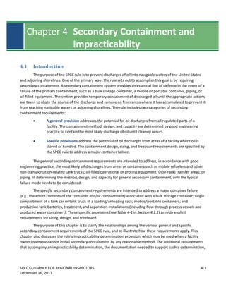
  • 20. SPCC GUIDANCE FOR REGIONAL INSPECTORS 4-20 December 16, 2013 Chapter 4: Secondary Containment and Impracticability Determination  Size of tank/container;  Safety considerations; and  Frequency of dike drainage and inspection. The following examples (Figure 4-5 and Figure 4-6) present secondary containment size calculations for hypothetical oil storage areas. The certifying PE (or owner/operator, in the case of qualified facilities) determines what volume constitutes sufficient freeboard for precipitation for secondary containment and should document in the Plan how the determination was made.
  • 21. SPCC GUIDANCE FOR REGIONAL INSPECTORS 4-21 December 16, 2013 Chapter 4: Secondary Containment and Impracticability Determination Figure 4-5: Sample calculation of containment size, using two design criteria. The following example compares two different design criteria: one based on the volume of the tank and one based on precipitation. Scenario: A 20,000-gallon horizontal tank is placed within an engineered secondary containment structure, such as a concrete dike. The tank is 35 feet long by 10 feet in diameter. The secondary containment area provides a 5-foot buffer on all sides (i.e., dike dimensions are 45 feet x 20 feet. Given the dike footprint, we want to determine the wall height necessary to provide sufficient freeboard for precipitation, based on (1) the tank storage capacity; (2) actual precipitation data. Several storm events in the recent past caused precipitation in amounts between 3.6 and 4.0 inches at this location, although greater amounts have also been reported in the past. Note: The factor for converting cubic feet to gallons is 7.48 gallons/ft 3 . 1. Calculation of secondary containment capacity, based on a design criterion of 110% of tank storage capacity: Containment surface area = 45 ft x 20 ft = 900 ft 2 Tank volume, based on 100% of tank capacity = 20,000 gallons Tank volume, in cubic feet = 20,000 gallons / 7.48 gallons/ft 3 = 2,674 ft 3 Wall height that would contain the tank’s volume = 2,674 ft 3 / 900 ft 2 = 2.97 ft Containment capacity with freeboard, based on 110% of tank capacity = 22,000 gallons Containment capacity, in cubic feet = 22,000 gallons / 7.48 gallons/ft 3 = 2,941 ft 3 Wall height equivalent to 110% of storage capacity = 2,941 ft 3 / 900 ft 2 = 3.27 feet Height of freeboard = 3.27 ft - 2.97 ft = 0.3 ft = 3.6 inches Therefore, a dike design based on a criterion of 110% of tank capacity provides a dike wall height of 3.27 feet. 2. Calculation of secondary containment capacity, based on rainfall criterion: After a review of historical precipitation data for the vicinity of the facility, the PE determined that a 4.5 inch rain event is the most reasonable design criterion for this diked area. Containment surface area = 45 ft x 20 ft = 900 ft 2 Tank volume, based on 100% of tank capacity = 20,000 gallons Tank volume, in cubic feet = 20,000 gallons / 7.48 gallons/ft 3 = 2,674 ft 3 Wall height that would contain the tank’s volume = 2,674 ft 3 / 900 ft 2 = 2.97 ft The height of the dike would need to be 3.35 feet (2.97 ft + 4.5 in). Therefore, a dike design based on a 4.5 inch rain event provides a dike wall height of 3.35 feet, or almost 1 inch higher than calculated using the 110% criterion. Conclusion: As noted from the comparison of the two design criteria illustrated above, the dike heights are similar although not exactly the same. The adequacy of the secondary containment freeboard is ultimately an engineering determination made by the PE and certified in the Plan.
  • 22. SPCC GUIDANCE FOR REGIONAL INSPECTORS 4-22 December 16, 2013 Chapter 4: Secondary Containment and Impracticability Determination Figure 4-6: Sample secondary containment calculations, for multiple tanks in a containment area. The EPA inspector has questioned the adequacy of the secondary containment based on the following scenario and wants to verify how much precipitation the dike area can hold and compare it to available precipitation data to determine if 112% is an adequate design criterion for this facility. Scenario: A 60 ft x 36 ft concrete dike surrounds one 20,000-gallon horizontal tank (10 ft diameter and 35 ft length) and two 10,000-gallon vertical tanks (each 10 ft diameter and 15 ft height). The dike walls are 18 inches (1.5 feet) tall. The SPCC Plan states that secondary containment is designed to hold 112% of the volume of the largest container. Notes:  The factor for converting gallons to cubic feet is 7.48 gallons/ft 3 .  The volume displaced by a cylindrical vertical tank is the tank volume within the containment structure and is equal to the tank footprint multiplied by height of the concrete dike. The tank footprint is equal to  D 2 /4, where D is the tank diameter. 1. Calculate total dike capacity: Total capacity of the concrete dike = length x width x height = 60 ft x 36 ft x 1.5 ft = 3,240 ft 3 = 24,235 gallons 2. Calculate net dike capacity, considering displacement from other tanks within the dike: The total capacity of the concrete dike is reduced by the volume displaced by other tanks inside the containment structure. The displacement is: = number of tanks x footprint x height of dike wall = 2  (10 ft) 2 /4 x 1.5 ft = 235.6 ft 3 = 1,762 gallons The net dike capacity, i.e., the volume that would be available in the event of a failure of the largest tank within the dike, is: = Total volume - tank displacement = 24,235 - 1,762 = 22,473 gallons = 3,004 ft 3 3. Calculate the amount of available freeboard provided by the dike, given the net dike capacity: The available freeboard volume is: = Net dike capacity - volume of largest tank within the dike = 22,473 - 20,000 = 2,473 gallons = 331 ft 3 This is equivalent, expressed in terms of the capacity of the largest tank, to: = Net dike capacity/volume of largest tank within the dike = 22,473 / 20,000 = 112% This available freeboard volume provides a freeboard height: = Available freeboard volume / dike surface area = 331 ft 3 / (60 ft x 36 ft) = 0.15 ft ≈1.8 in Therefore, this dike provides sufficient freeboard for 1.8 inches of precipitation. Conclusion: The EPA inspector should review the Plan and/or inquire about the precipitation event considered in determining that sufficient freeboard for precipitation is provided. The adequacy of the secondary containment freeboard is ultimately an engineering determination made by the PE and is certified in the Plan. This example serves only as a guide on doing the calculations for certain circumstances in which the inspector has concerns with the freeboard volume associated with the secondary containment design.
  • 23. SPCC GUIDANCE FOR REGIONAL INSPECTORS 4-23 December 16, 2013 Chapter 4: Secondary Containment and Impracticability Determination 4.3.3 Role of the EPA Inspector in Evaluating Sufficient Freeboard When reviewing an SPCC Plan, the EPA inspector should evaluate whether the size of secondary containment is adequate to meet the freeboard requirement. When examining the secondary containment measures for bulk storage containers, mobile or portable oil containers, and oil production facility bulk storage containers, the inspector should ensure that the Plan documents that the secondary containment can hold the entire capacity of the largest single container, plus sufficient freeboard to contain precipitation. Whatever method is used to calculate the amount of freeboard that is “sufficient” for the facility and container configuration should be documented in the Plan. To determine whether secondary containment is sufficient, the EPA inspector may:  Verify that the Plan specifies the capacity of secondary containment along with supporting documentation, such as calculations for comparing freeboard capacity to the volume of precipitation in an expected storm event. - If calculations are not included with the Plan, and the inspector suspects the secondary containment is inadequate, the inspector may request supporting documentation from the owner/operator.P 83 - If diked area calculations appear inadequate, review local precipitation data such as data from airports or the National Weather Service,P 84 P as needed.  Review operating procedures, storage tank design, and/or system controls for preventing inadvertent overfilling of oil storage tanks that could affect the available capacity of the secondary containment structure.  Confirm that the secondary containment capacity can reasonably handle the contents of the largest tank on an ongoing basis (i.e., including during rain events).  During the inspection, verify that the containment structures and equipment are maintained and that the SPCC Plan is properly implemented. 4.4 Issues Related to Secondary Containment Requirements The following sections describe issues related to all secondary containment requirements, general and specific. 83 Industry guidance recommends that facility owners/operators include any secondary containment capacity calculations and/or design standards with the Plan. API Bulletin D16, “Suggested Procedure for Development of Spill Prevention Control and Countermeasure Plans,” contains example calculations to which inspectors may refer. 84 National Weather Service, Hydrometeorological Design Studies Center, Current Precipitation Frequency Publications, available at http://www.nws.noaa.gov/oh/hdsc/currentpf.htm#N2.
  • 24. SPCC GUIDANCE FOR REGIONAL INSPECTORS 4-24 December 16, 2013 Chapter 4: Secondary Containment and Impracticability Determination 4.4.1 Passive versus Active Measures of Secondary Containment In some situations, permanent containment structures, such as dikes, may not be feasible (e.g., may cause pooling of liquids around electrical equipment which may present a hazard). Section 112.7(c) specifically allows for the use of active containment measures (countermeasures or spill response capability), which prevent a discharge to navigable waters or adjoining shorelines. Active containment measures are those that require deployment or other specific action by the owner or operator. These measures may be deployed either before the start of an activity involving the handling of oil, or in reaction to a discharge, so long as the active measure is designed to prevent an oil spill from reaching navigable water or adjoining shorelines. Passive measures are permanent installations and do not require deployment or action by the owner/operator. Active measures (countermeasures) include, but are not limited to:  Placing a properly designed storm drain cover over a drain to contain a potential spill in an area where a transfer occurs, prior to the transfer activity. Storm drains are normally kept uncovered; deployment of the drain cover prior to the transfer activity may be an acceptable active measure to prevent a discharge from reaching navigable waters or adjoining shorelines through the drainage system.  Placing a storm drain cover over a drain in reaction to a discharge, before the oil reaches the drain. If deployment of a drain cover can reliably be achieved in time to prevent a discharge of oil from reaching navigable waters or adjoining shorelines, this may be an acceptable active measure. This method may be risky, however, and is subject to a good engineering judgment on what is realistically and reliably achievable, particularly under adverse circumstances.  Using spill kits in the event of an oil discharge. The use of spill kits, strategically located and ready for deployment in the event of an oil discharge, may be an acceptable active measure, in certain circumstances, to prevent a spill from reaching navigable waters or adjoining shorelines. This method may be risky and is subject to good engineering judgment, considering the volume most likely expected to be discharged and proximity to navigable waters or adjoining shorelines.  Use of spill response capability (spill response teams) in the event of an oil discharge. This method differs from activating an oil spill contingency plan (see §112.7(d)) because the response actions are specifically designed to contain an oil discharge prior to reaching navigable waters or adjoining shorelines. Such actions may include the emergency construction/deployment of dikes, curbing, diversionary structures, ponds, and other temporary containment methods (such as sorbent materials), so long as they can be implemented in time to prevent the spilled oil from reaching navigable waters or adjoining shorelines. This method may be risky and reliance on oil spill response capability for secondary containment is subject to good engineering judgment.
  • 25. SPCC GUIDANCE FOR REGIONAL INSPECTORS 4-25 December 16, 2013 Chapter 4: Secondary Containment and Impracticability Determination  Closing a gate valve that controls drainage from an undiked area prior to a discharge. If the gate valve is normally kept open, closing it before an activity that may result in an oil discharge may be an acceptable active measure to prevent a spill from reaching navigable waters or adjoining shorelines. Note that the rule requires that bypass valves for diked areas be sealed closed (§§112.8(c)(3)(i) and 112.12(c)(3)(i)). Considerations in Selecting an Active Containment Measure The use of active containment as a strategy to address discharges should be carefully evaluated. The efficacy of active containment measures to prevent a discharge depends on their technical effectiveness (e.g., mode of operation, absorption rate), placement and quantity, and timely deployment prior to or following a discharge. For discharges that occur only during attended or observed activities, such as those occurring during transfers, an active measure (e.g., sock, mat, other portable barrier, or land-based response capability) may be appropriate, provided that the measure is capable of containing the most likely volume of an oil discharge from a typical failure mode, and is timely and properly constructed/deployed. Ideally, in order to further reduce the potential for an oil discharge to reach navigable waters or adjoining shorelines, the active measure should be deployed prior to initiating the activity with potential for a discharge. For certain active measures, however, such as the use of “kitty litter” or other sorbent material, it may be impractical to pre-deploy the measure. In such cases, the sorbent material should be readily available so that it can be used immediately after a spill occurs but before it can spread. Portable tanks can be equipped with a spill kit to be used in the event of a discharge during transfers. The spill kit should be sized, however, to effectively contain the volume of oil that could be discharged. Most commercially available spill kits are intended for relatively small volumes (up to approximately 150 gallons of oil). Active containment measures can be used to satisfy the general secondary containment requirement when they are capable of containing the most likely discharge volume identified in the SPCC Plan. Elements to consider may include the capacity of the containment measure, effectiveness, timely implementation, and the availability of facility personnel and equipment to implement the active measure effectively. For example, a discharge of 600 gallons would require deploying more than 900 “high-capacity” sorbent pads (20 inches by 20 inches) since each pad absorbs less than 0.7 gallons of oil. The same spill volume would require nine sorbent blankets, each measuring 38 inches by 144 feet and weighing approximately 40 pounds. The rapid deployment of such response equipment and material would be difficult to achieve under most circumstances, particularly if only a few individuals are present when the discharge occurs, or during adverse conditions (e.g., rainfall, fire). Using an active measure to meet the specific secondary containment requirement for a bulk storage container may be difficult because the containment system must be sized for the entire capacity of the bulk oil Tip – Active vs. passive containment measures Active: The containment measure involves a certain action by facility personnel before or after the discharge occurs. These actions are also referred to as spill countermeasures. Passive: The containment measure remains in place regardless of the facility operations and therefore does not require an action by facility personnel.
  • 26. SPCC GUIDANCE FOR REGIONAL INSPECTORS 4-26 December 16, 2013 Chapter 4: Secondary Containment and Impracticability Determination storage container. Therefore, the use of active measures for larger oil containers may not be appropriate or in accordance with good engineering practice or sound industry standards. In certain circumstances, sorbents, such as socks, booms, pads, or loose materials may be used to complement passive measures. For example, where berms around transfer areas are open on one side for access, and where the ground surface slopes away from the opening with no nearby drains, sorbent material may be effective in preventing small quantities of oil from escaping the bermed area in the event of a discharge. The secondary containment approach implemented at a facility need not be “one-size-fits-all.” Different approaches may be taken for the same activity at a given facility, depending on the material and location. For example, the SPCC Plan may specify that drain covers and sorbent material be pre-deployed prior to transfers of low viscosity oils in certain areas of a facility located in close proximity to drainage structures or navigable waters. For other areas and/or other products (e.g., highly viscous oils), the Plan may specify that sufficient spill response capability (spill response teams) are available for use in the event of a discharge, so long as personnel and equipment are available at the facility and these measures can be effectively implemented in a timely manner to prevent oil from reaching navigable waters or adjoining shorelines. Evaluating the ability of active secondary containment measures deployed after a discharge to prevent oil from reaching navigable waters or adjoining shorelines involves considering the time it would take to discover the discharge, the time for the discharge to reach navigable waters or adjoining shorelines, and the time necessary to deploy the active secondary containment measure. For some active containment measures such as the use of sorbent materials, the amount of oil the secondary containment measure can effectively contain, including the potential impact of precipitation on sorption capacity, is also a critical factor. Good engineering practice would indicate that active secondary containment measures may be used to satisfy the general secondary containment requirements of §112.7(c) only in certain circumstances. The use of an active measure containment strategy can be risky if not properly designed, evaluated and implemented. If an active measure fails to prevent an oil discharge from reaching navigable waters or adjoining shorelines, the owner or operator is liable for the discharge and cleanup, and is responsible for properly reporting it to the National Response Center. Furthermore, even when used to comply with §112.7(c), active measures should be limited to those situations where a PE has determined that the typical failure mode involves a small volume of oil. Generally, active containment measures are not appropriate for satisfying the specific containment requirements for a major container failure. Inspectors should closely review the SPCC Plan and evaluate the rationale, equipment and implementation of such a strategy, as in most cases, this would not be considered good engineering practice. Deployment of Active Measures Active measures are not appropriate for all situations with the potential for an oil discharge. As noted above, active measures often have limited absorption or containment capacity. Additionally, storage tanks, piping, and other containers pose a risk of discharge during off-hour periods when facility personnel are generally not on site or are too few in number to detect a discharge in a timely manner and deploy the containment measure(s) in order to prevent a discharge of oil to navigable waters or adjoining shorelines. Pre-
  • 27. SPCC GUIDANCE FOR REGIONAL INSPECTORS 4-27 December 16, 2013 Chapter 4: Secondary Containment and Impracticability Determination deployment of active measures in a “fixed” configuration may be problematic since sorbent materials or portable barriers are typically not engineered for long-term deployment, and their performance may be affected by precipitation, ultraviolet light degradation, or cold temperature. Moreover, in some cases, the deployment of an active measure can interfere with other systems; for example, by impeding the proper operation of drainage structures (e.g., drain cover). For these reasons, engineered structures (such as dikes and berms, curbing, spill diversion ponds, or similar systems) remain the most effective means of spill control and containment for oil storage containers. The SPCC Plan must describe the procedures used to deploy the active measures, explain how the use of active measures is appropriate to the situation, and explain the methods for discharge discovery that will be used to determine when deployment of the active measures is appropriate (§112.7(a)(3)(iii) and (iv)). The Plan should, for instance, discuss whether active measures will be put in place before a potential discharge event (e.g., a boom placed around a vehicle before fueling activities begin) or whether the active measures will be deployed quickly after a spill occurs as a countermeasure (e.g., sorbents on hand and readily available). The Plan should describe the amount of materials available and the location where they are stored, and the manpower required to adequately deploy the material in a timely manner. Both the amount and location of materials should be determined based on good engineering practice, taking into consideration the potential volume of a discharge and the time necessary to deploy the measure to prevent a discharge to navigable waters or adjoining shorelines. Some of this information may already be described in other existing documents at the facility, in which case, these documents should be referenced in the SPCC Plan and be available at the time of an inspection. Using Active Measures with Oil-Filled Operational Equipment Oil-filled operational equipment (e.g., electrical transformers, capacitors, switches) poses unique challenges; permanent (passive) containment structures, such as dikes, may not always be feasible. Oil-filled operational equipment as defined in §112.2 is only subject to the general secondary containment provision, and the owner/operator may use the flexibility of active containment measures as described above. However, active containment measures may be risky because they require the ability to detect a discharge, and these measures must be implemented effectively and in a timely manner to prevent oil from reaching navigable waters and adjoining shorelines, as required by §112.7(a)(3)(iii) and (c). As provided in §112.7(k), owners and operators of facilities with eligible oil-filled operational equipment have the option to prepare an oil spill contingency plan and a written commitment of manpower, equipment, and materials to expeditiously control and remove any oil discharged that may be harmful, in lieu of general secondary containment, without having to make an individual impracticability determination as required in §112.7(d). Role of the EPA Inspector in Evaluating the Use of Active Measures of Secondary Containment Inspectors should carefully evaluate the use of active measures and determine if the equipment and personnel are available for deployment of this secondary containment method. The EPA inspector should inspect the facility to determine whether the active measures are appropriate for the facility – i.e., the inspector should note whether material storage locations are reasonable given the time necessary to deploy measures,
  • 28. SPCC GUIDANCE FOR REGIONAL INSPECTORS 4-28 December 16, 2013 Chapter 4: Secondary Containment and Impracticability Determination and whether the amount of available materials is sufficient to handle the anticipated discharge volume. In addition, the inspector should document whether the owner/operator of the facility is keeping the necessary records. Upon EPA inspection, a facility owner/operator should be able to demonstrate that facility personnel are able to carry out the deployment procedure as written. The EPA inspector should verify that the facility’s SPCC Plan contains the following items, and that items in the Plan are observed in the field and/or verified through discussions with facility personnel. Questions for the EPA inspector to consider in evaluating the adequacy of active measures are also provided below.  Explanation showing why the use of active measures is appropriate. - What is the expected/most likely potential discharge volume, and is the active measure appropriately sized to contain the spill? - What is the discharge detection method and is it appropriate? - How much time is required to deploy the selected active measure? - Given these factors, is the active measure a reasonable approach?  Detailed description of deployment procedures. - Will active measures be put in place before or after a spill occurs? - If measures are to be activated after a spill occurs, does the Plan describe the method of discharge detection? - Are the equipment and personnel available to deploy/implement the proposed active containment measure in an effective and timely manner to prevent oil from reaching navigable waters or adjoining shorelines? - Does the Plan identify drainage pathways and the appropriate deployment location(s) for the active measures?  Description of all necessary materials and the location where they are stored (i.e., location of drain covers, spill kits, or other spill response equipment). - In cases where spill kits or sorbent materials are to be used, does the Plan describe the amount of materials available? - Are inventory and/or maintenance logs provided to ensure that spill response equipment/materials are currently in sufficient supply and in good working condition (i.e., not damaged, expired, or used up)? - Are the equipment/materials located such that personnel can realistically get to the equipment and deploy it quickly enough to prevent a discharge to navigable waters or adjoining shorelines? That is, are the material and equipment accessible (not locked, or a key is available), and are they located close enough to the potential source of discharge?
  • 29. SPCC GUIDANCE FOR REGIONAL INSPECTORS 4-29 December 16, 2013 Chapter 4: Secondary Containment and Impracticability Determination  Description of facility staff responsible for deploying active measures. - Are training records up to date? - Have the personnel involved in activities for which the active measures might be deployed been trained (e.g., are they familiar with the location and use of spill response materials, drainage conditions)? - Is there sufficiently trained facility staff present at all times to effectively deploy the measures in the event of a discharge? Furthermore, the EPA inspector may review records and documentation such as:  Personnel training records  Drill records  Deployment logs The EPA inspector does not need to require the facility personnel to actually deploy the active measure (e.g., through a demonstration or drill) to show that the measure is adequate and can be deployed in a timely manner. However, the inspector may ask a series of questions in order to determine if the procedures for deploying an active measure are well understood. 4.4.2 “Sufficiently Impervious” Section 112.7(c) states that the entire secondary containment system, “including walls and floor, must be capable of containing oil and must be constructed so that any discharge from a primary containment system ... will not escape containment before cleanup occurs.” With respect to bulk storage containers at onshore facilities (except oil production facilities), §§112.8(c)(2) and 112.12(c)(2) state that diked areas must be “sufficiently impervious to contain oil.” The purpose of the secondary containment requirement is to prevent discharges as described in §112.1(b); therefore, effective secondary containment methods must be able to contain oil until the oil is cleaned up. The rule does not specify permeability, hydraulic conductivity, or retention time performance criteria for these provisions (i.e., “sufficiently impervious” does not necessarily mean indefinitely impervious). Instead, the owner/operator and/or the certifying PE have the flexibility to determine how best to design the containment system to prevent a discharge to navigable waters or adjoining shorelines. This determination is based on a good engineering practice evaluation of the facility configuration, product properties, and other site-specific conditions. For example, a sufficiently impervious retaining wall, dike, or berm, including the walls and floors, must be constructed so that any discharge from a primary containment system will not escape the secondary containment system before cleanup occurs and before the oil reaches navigable waters or adjoining shorelines (§§112.7(c), 112.8(c)(2) and 112.12(c)(2)). In other words, secondary containment structures such as dikes, berms and retaining walls can be considered sufficiently impervious as long as they allow for cleanup to occur in
  • 30. SPCC GUIDANCE FOR REGIONAL INSPECTORS 4-30 December 16, 2013 Chapter 4: Secondary Containment and Impracticability Determination time to prevent a discharge to navigable waters or adjoining shorelines. Ultimately, the determination of imperviousness should be verified by a PE and documented in the SPCC Plan. The preamble to the 2002 SPCC rule amendments states that “a complete description of how secondary containment is designed, implemented, and maintained to meet the standard of sufficiently impervious is necessary” (67 FR 47102, July 17, 2002). Therefore, pursuant to §112.7(a)(3)(iii) and (c), the Plan should address how the secondary containment is designed to effectively contain oil until it is cleaned up. Control and/or removal of vegetation may be necessary to maintain the imperviousness of the secondary containment and to allow for the visual detection of discharges. The owner or operator should monitor the conditions of the secondary containment structure to ensure that it remains impervious to oil. Repairs of excavations or other penetrations through secondary containment need to be conducted in accordance with good engineering practice. The earthen floor of a secondary containment system may be considered “capable of containing oil” until cleanup occurs, or “sufficiently impervious” if there is no subsurface conduit to navigable waters allowing the oil to reach navigable waters before it is cleaned up. Should oil reach navigable waters or adjoining shorelines, it is a reportable discharge under 40 CFR part 110. The suitability of earthen material for secondary containment systems may depend on the properties of both the product stored and the soil. For example, compacted local soil may be suitable to contain a viscous product, such as liquid asphalt cement, but may not be suitable to contain gasoline. Permeability through the wall (or wall-to-floor interface) of the structure may result in a discharge to navigable waters or adjoining shorelines and must be carefully evaluated. In certain geographic locations, the native soil (e.g., clay) may be determined as sufficiently impervious. However, in many more instances good engineering practice would generally not allow the use of a facility’s native soil alone as secondary containment when the soil is not homogenous. In fact, certain state requirements may restrict the use of soil as a means of secondary containment, and many state regulations explicitly forbid the discharge of oil on soil. Pennsylvania’s Storage Tank and Spill Prevention Act, for example, requires that facilities take immediate steps to prevent injury from any discharge of a substance that has the potential to flow, be washed or fall into waters, and endanger downstream users. Pennsylvania’s law requires that residual substances be removed within 15 days from the ground or affected waters. Discharges to soil and groundwater may violate other federal regulations (and violate Section 311(b)(3) of the Clean Water Act if an oil discharge to groundwater impacts a navigable water or adjoining shoreline). The EPA inspector should strongly urge facility owners and operators to investigate and comply with all state and local requirements. An inspector who notices potential violations of other statutes or regulations should contact the appropriate authorities for follow-up with the facility. In summary, the owner/operator must base determinations of sufficiently impervious secondary containment design on good engineering practice and site-specific considerations and this must be documented in the Plan.
  • 31. SPCC GUIDANCE FOR REGIONAL INSPECTORS 4-31 December 16, 2013 Chapter 4: Secondary Containment and Impracticability Determination Role of the EPA Inspector in Evaluating “Sufficiently Impervious” Like other technical aspects of the SPCC Plan, the determination that a facility's soil is sufficiently impervious must be made on a case-by-case basis by the certifying PE (or owner/operator, in the case of qualified facilities). The EPA inspector should determine whether the facility’s secondary containment is sufficiently impervious, based on a review of the SPCC Plan, inspection reports, maintenance records, and an observation of site conditions. The EPA inspector may ask to see any calculations or engineering justifications (as applicable) used in determining levels of imperviousness; this information should be maintained with the Plan to facilitate the inspector’s review. To evaluate whether secondary containment is sufficiently impervious, the EPA inspector may consider the following:  Whether the SPCC Plan describes how secondary containment is designed, implemented, and maintained to be sufficiently impervious. The certification of the Plan’s adequacy is the responsibility of the PE (or the owner or operator of a qualified facility) and a determination of sufficient imperviousness may be based strictly on geotechnical knowledge of soil classification and best engineering judgment. The inspector may review records of hydraulic conductivity tests, if such tests were conducted to ascertain the imperviousness of the secondary containment structure. The inspector may also review drainage records that are required to be kept by the facility owner/operator in accordance with §112.8(c)(3), §112.9(b)(1), or §112.12(c)(3). If, for example, facility personnel never drain the outdoor containment, then the inspector may pose follow-up questions to clarify how the facility removes precipitation after heavy rainfall, since lack of rainfall accumulation could indicate that the water is escaping the containment structure through the walls or floor.  Procedures for how the owner/operator minimizes and evaluates the potential for corrosion of the bottom/bases of bulk storage containers that cannot be visually inspected. Corrosion of container bottom is addressed in part by integrity testing of bulk storage containers under §112.8(c)(6) or §112.12(c)(6). If a facility owner/operator cannot certify that the material under the container is sufficiently impervious (whether earthen or manmade), the inspector should consider: - Whether the inspection and integrity testing program in the Plan includes an internal inspection, in accordance with industry standards. The scope of this internal inspection should include the bottom plate. Since the bottom plate cannot be examined from the underside, the only inspection available is to assess the fitness of the bottom plate via an internal inspection. (See Chapter 7: Inspection, Evaluation, and Testing for more information on integrity testing.) - Whether the owner/operator of the facility has a system in place to detect oil discharges from a container bottom in order to commence cleanup before a discharge escapes the containment systems.
  • 32. SPCC GUIDANCE FOR REGIONAL INSPECTORS 4-32 December 16, 2013 Chapter 4: Secondary Containment and Impracticability Determination  Evidence of stained soil or stressed vegetation outside the containment area as well as at nearby outfalls or other areas affected by runoff from the secondary containment structure. For example, at onshore oil production facilities, there may be oil stains or white areas and white salt crystal deposits on the outside of berm walls and on the ground surface farther away from the berm. These deposits may indicate that oil and produced water has flowed through the secondary containment and that the structure may not be sufficiently impervious.  How the secondary containment is constructed (materials and method of construction). The inspector should consider the type of soil (if soil is used). Floor and walls constructed of sandy material, for example, may not be appropriate to hold refined products such as gasoline. If earthen material is used, then it should have a high clay content and be properly compacted, not simply formed into a mound. Untreated cinder blocks used for containment should be closely evaluated by an inspector due to their porous nature.  If a facility considers the earthen floor of a secondary containment system to be sufficiently impervious, the inspector should consider any underground pathway that could lead to navigable waters. 4.4.3 Facility Drainage (Onshore Facilities) The facility drainage requirements of §§112.8(b) and 112.12(b) are design standards for secondary containment (not additional secondary containment requirements) and are therefore eligible for deviations that provide equivalent environmental protection in compliance with §112.7(a)(2) and as determined appropriate by a PE. Chapter 3: Environmental Equivalence discusses ways to evaluate whether facility drainage systems that deviate from the specified design standards are “environmentally equivalent” and comply with §112.7(a)(2) (see Section 3.3.1). The following sections describe how the facility drainage provisions at §§112.8(b) and 112.12(b) relate to each other and to the secondary containment requirements.
  • 33. SPCC GUIDANCE FOR REGIONAL INSPECTORS 4-33 December 16, 2013 Chapter 4: Secondary Containment and Impracticability Determination §§112.8(c)(3) and 112.12(c)(3) Not allow drainage of uncontaminated rainwater from the diked area into a storm drain or discharge of an effluent into an open watercourse, lake, or pond, bypassing the facility treatment system unless you: (i) Normally keep the bypass valve sealed closed. (ii) Inspect the retained rainwater to ensure that its presence will not cause a discharge as described in § 112.1(b). (iii) Open the bypass valve and reseal it following drainage under responsible supervision; and (iv) Keep adequate records of such events, for example, any records required under permits issued in accordance with §§ 122.41(j)(2) and 122.41(m)(3) of this chapter. Note: The above text is an excerpt of the SPCC rule. Refer to 40 CFR part 112 for the full text of the rule. Facility Drainage Control from Diked Areas When a dike (the term as used here also includes other barrier methods such as berms, retaining walls, curbing, weirs, or booms) is used as the containment method to satisfy either general or specific secondary containment requirements, then facility drainage requirements also apply. The requirements for diked areas at onshore facilities (except oil production facilities) are found in §112.8(b)(1), 112.8(b)(2) (or §112.12(b)(1), and 112.12(b)(2)); for diked areas at onshore oil production facilities they are found in §112.9(b)(1). Drainage from diked storage areas can be accomplished by several means such as valves, manually activated pumps, or ejectors. If dikes are drained using valves, they must be of manual design to prevent an uncontrolled discharge outside of the dike, such as into a facility drainage system or effluent treatment system, except where facility systems are designed to control such a discharge (§§112.8(b)(1) and 112.12(b)(1)). Although not required by the rule, owners and operators should strongly consider locking valves controlling dike or remote impoundment areas, especially when they can be accessed by non-facility personnel. For diked areas serving as secondary containment for bulk storage containers, §§112.8(c)(3) and 112.12(c)(3) require that storm water accumulations be inspected for the presence of oil and that records of the drainage events be maintained. Prior to draining these areas, accumulated oil on the rainwater must be removed and returned to storage or disposed of in accordance with legally approved methods. Facility Drainage Control from Undiked Areas When secondary containment requirements are addressed through facility drainage controls, such as culverting, gutters, ponds, or other drainage systems, the requirements in §112.8(b)(3) and (4), or §112.12(b)(3) and (4) apply. For example, a facility may §§112.8(b) and 112.12(b) Facility drainage. (1) Restrain drainage from diked storage areas by valves to prevent a discharge into the drainage system or facility effluent treatment system, except where facility systems are designed to control such discharge. You may empty diked areas by pumps or ejectors; however, you must manually activate these pumps or ejectors and must inspect the condition of the accumulation before starting, to ensure no oil will be discharged. (2) Use valves of manual, open-and-closed design, for the drainage of diked areas. You may not use flapper-type drain valves to drain diked areas. If your facility drainage drains directly into a watercourse and not into an on-site wastewater treatment plant, you must inspect and may drain uncontaminated retained stormwater, as provided in paragraphs (c)(3)(ii), (iii), and (iv) of this section. Note: The above text is an excerpt of the SPCC rule. Refer to 40 CFR part 112 for the full text of the rule.
  • 34. SPCC GUIDANCE FOR REGIONAL INSPECTORS 4-34 December 16, 2013 Chapter 4: Secondary Containment and Impracticability Determination choose to use the existing storm drainage system to meet secondary containment requirements by channeling discharged oil to a remote containment area to prevent a discharge to navigable waters or adjoining shorelines. The facility drainage system must be designed to flow into ponds, lagoons, or catchment basins designed to retain oil or return it to the facility. Catchment basins must not be located in areas subject to periodic flooding (§§112.8(b)(3) and 112.12(b)(3)). Conversely, the owner or operator of a facility does not have to address the undiked area requirements of §112.8(b)(3) and (4) or §112.12(b)(3) and (4) if the facility does not use drainage systems to meet one of the secondary containment requirements in the SPCC rule. For example, if the SPCC Plan documents the use of an active containment measure (such as a combination of sorbents and a spill mat) that is effective to prevent a discharge to navigable waters or adjoining shorelines, then secondary containment has been provided and it is not necessary to alter drainage systems at the facility. The facility drainage system design requirements in §112.8(b)(3) and (4) or §112.12(b)(3) and (4) apply only when the facility uses these drainage systems to comply with the secondary containment provisions of the rule. The EPA inspector should determine if the facility’s documentation in the Plan identifies whether the final ponds, lagoons, or catchment basins are designed/sized to meet the appropriate general and/or specific secondary containment requirements. The following examples help to illustrate how to determine the appropriate size of the ponds, lagoons, or catchment basins:  General Secondary Containment. A facility owner/operator may use a storm water drainage system that flows to a containment pond to address the general secondary containment requirements of §112.7(c) for a piece of operational equipment (including electrical oil-filled equipment). The secondary containment system must be designed to address the typical failure mode and to contain the volume of oil most likely to be discharged as determined according to good engineering practice and documented in the SPCC Plan (not necessarily a complete/major container failure).  Specific Secondary Containment. If a facility owner/operator uses a storm water drainage system that flows to a catchment basin to comply with the specific secondary containment requirements for a bulk storage container, the secondary containment system must be designed to contain the capacity of the largest bulk storage container located inside the containment system (with appropriate freeboard for precipitation) as dictated by the rule’s requirements in §§112.8(c)(2) or 112.12(c)(2). The specific secondary containment requirement is based on a worst case container failure in which the entire capacity of the container is discharged.  General and Specific Secondary Containment. In a case where a drainage system to a final catchment basin is used to meet multiple secondary containment needs for the facility, including compliance with both general and specific secondary containment requirements, the system’s design will need to meet the most stringent rule requirement (typically sized for the specific secondary containment requirement).
  • 35. SPCC GUIDANCE FOR REGIONAL INSPECTORS 4-35 December 16, 2013 Chapter 4: Secondary Containment and Impracticability Determination §112.9(b) Oil production facility drainage. (1) At tank batteries and separation and treating areas where there is a reasonable possibility of a discharge as described in §112.1(b), close and seal at all times drains of dikes or drains of equivalent measures required under §112.7(c)(1), except when draining uncontaminated rainwater. Prior to drainage, you must inspect the diked area and take action as provided in § 112.8(c)(3)(ii), (iii), and (iv). You must remove accumulated oil on the rainwater and return it to storage or dispose of it in accordance with legally approved methods. (2) Inspect at regularly scheduled intervals field drainage systems (such as drainage ditches or road ditches), and oil traps, sumps, or skimmers, for an accumulation of oil that may have resulted from any small discharge. You must promptly remove any accumulations of oil. Note: The above text is an excerpt of the SPCC rule. Refer to 40 CFR part 112 for the full text of the rule. Oil Production Facility Drainage Owners and operators of oil production facilities must close and seal drains on secondary containment systems associated with tank batteries and separation and treating areas (both dikes and other equivalent measures required under §112.7(c)(1)) at all times, except when draining uncontaminated rainwater (§112.9(b)(1)). Prior to drainage, the owner/operator must inspect the diked area and take action as provided in §112.8(c)(3)(ii), (iii), and (iv). If oil is present, then the owner/operator must remove accumulated oil on the rainwater and return it to storage or dispose of it in accordance with legally approved methods. Owners and operators of oil production facilities must also inspect field drainage systems (such as drainage ditches or road ditches), and oil traps, sumps, or skimmers at regularly scheduled intervals for an accumulation of oil that may have resulted from any small discharge and promptly remove any accumulations of oil from these systems. EPA inspectors should evaluate facility records to verify compliance with the drainage procedures described in §112.8(c)(3). Any storm water discharge records maintained at the facility in accordance with the NPDES requirements in §122.41(j)(2) or 122.41(m)(3) are acceptable to satisfy the recordkeeping requirements of §§112.8(c)(3)(iv) or 112.12(c)(3)(iv). Field observations may also shed light on compliance with the drainage provisions of the rule. Role of the EPA Inspector in Evaluating Onshore Facility Drainage The EPA inspector should review the facility’s SPCC Plan to ensure that the drainage procedures are documented and records are maintained. The EPA inspector should also examine the facility to determine whether the drainage procedures are implemented as described in the SPCC Plan and whether they are appropriate for the facility. If a facility uses drainage systems to meet one or more secondary containment requirements, the EPA inspector should evaluate whether the final ponds, lagoons, or catchment basins are designed/sized in accordance with the appropriate general and/or specific secondary containment requirements. The EPA inspector should also evaluate the facility records to verify compliance with the drainage procedures described in §112.8(c)(3). 4.4.4 Man-made Structures If an oil storage container at a regulated facility is located inside a building, the PE certifying the SPCC Plan may take into consideration the ability of the building walls and/or drainage systems to serve as secondary