SlideShare a Scribd company logo
1 of 42
SECTION 4.1

FUEL STORAGE


4.1.1 Introduction


4.1.2 Regulatory Requirements


4.1.3 Standard Operating Practices

         A. SETBACK REQUIREMENTS

         B. CONSTRUCTION MATERIALS

         C. SECONDARY CONTAINMENT

         D. CATHODIC PROTECTION

         E. OVERFLOW/SPILL CONTAINMENT

         F. FOUNDATIONS, SUPPORTS AND ANCHORS

         G. PIPING, PUMPS AND VALVES

         H. LEAK DETECTION

         I. PAINTING AND COATINGS

         J. UPGRADING REQUIREMENTS

         K. ACCESS AND PROTECTION

         L. CONTROL AND DISCHARGE OF IMPOUNDED RAINWATER

         M. REGISTRATION

         N. WITHDRAWAL FROM SERVICE

         O. SPILL/LEAK RESPONSE

         P. BIODEISEL
4.1.4 Colleague Examples
SECTION 4.1

FUEL STORAGE


4.1.1 Introduction


The storage of diesel fuel and gasoline in aboveground and underground storage tanks, if not
managed properly, represents potential environmental liabilities to golf course operators.
Environmental impacts which can result from fuel storage facilities are predominantly related to
product spills during filling and emptying of the tank, and releases from leaking tanks. Product spills
and leaking tanks can create the following problems:


1. Soils both on and off the golf course property can be contaminated.

2. Vapors from light or volatile hydrocarbons can migrate through the soil and into basements
   and sewers creating health risks as well as explosion hazards.

3. Contaminants can run along the ground surface and contaminate ponds, creeks and other
   surface water bodies.
4. Contaminants can travel through the soil and contaminate groundwater supplies.

   This is known as "leaching".


Statistics have shown that approximately 70% of all underground storage tanks (USTs) greater than
15 years old are leaking. Given that costs associated with cleaning up soil and groundwater
contamination can exceed $100,000 on certain sites, there is considerable incentive to ensuring
that fuel storage facilities are designed, constructed and operated properly.


Please note: the information provided in this subsection should be used with caution.
Although fire codes are generally the same, specific provincial and even municipal
requirements do vary.


In addition, superintendents should ensure that all contractors employed to perform work
on their fuel storage area are registered with their provincial fuel tank society.


4.1.2 Regulatory Requirements


Specific design, construction and operation requirements for aboveground storage tanks (ASTs) and
USTs are contained in the fire codes for the particular jurisdiction. For example, the National Fire
Code applies on federal lands (National Parks, Reserves, Armed Forces), while provincial fire codes
apply within the provinces.


         Did You Know . . .
Storage tanks are defined as closed containers having capacities greater than 250 L (66 USG),
used for the storage of flammable or combustible materials. Therefore they apply to just
about all fuel storage facilities, except for small containers and drums. It should be noted that
gasoline is classified as a flammable liquid, whereas diesel fuel is classified as a combustible.


The fire codes contain a number of common requirements for ASTs and USTs. These include the
following:

1. Setbacks from property lines and buildings

2. Construction materials

3. Cathodic protection (for corrosion protection)

4. Secondary containment (for containment of spills)

5. Inventory control requirements to detect product losses

6. Testing, reporting and upgrading requirements (to ensure that leaks do not develop).


Specific requirements for the different provinces and for federal lands are summarized on Table 4.1
for ASTs and on Table 4.2 for USTs.                 A summary of regulatory contacts is presented
in Table 4.3.

In the event of a significant spill or leak from an AST or a UST, federal and provincial legislation
requires that the owner/operator of the tank report the release to the following parties:

•   the owner of the land

•   the owner of any land onto which contamination migrates

•   the appropriate environment ministry (i.e., on federal lands it should be reported to
    Environment Canada whereas on provincial lands it should be reported to the provincial
    ministry).


The definition of a significant spill or leak varies among provinces. Table 4.6 presents the spill
volumes that require reporting in the individual provinces. In addition, Table

4.6 identifies the agencies to which the spills should be reported.


In addition to the regulatory requirements outlined in Tables 4.1, 4.2 and 4.4, a number of other
codes and standards exist which specify requirements for ASTs and USTs.
These include the following:


UNDERWRITERS LABORATORY CANADA (ULC)


ULC develops standards for the insurance industry. Because of the fire and environmental risks
associated with storage of petroleum products, ULC has developed standards for AST and UST
materials and construction. Therefore, in order to obtain insurance, it is necessary to ensure that
tanks are constructed to ULC standards.


ULC standards relate to specific material, welding and fabrication requirements, and are very
technical. From a practical point of view, the fire codes refer to ULC standards, and tank
manufacturers construct tanks to ULC standards. In addition, ULC will certify certain manufacturers
as qualified to construct ASTs and USTs to their standards. Therefore from the golf course
superintendent’s perspective, it is important to ensure that any tanks purchased are ULC-certified.


The ULC Mark
The ULC Mark is nationally recognized for many specific product categories, including building
materials and fire protection and suppression products.


Visit the ULC Website: www.ulc.ca


CANADIAN COUNCIL OF MINISTERS OF THE ENVIRONMENT (CCME)
CCME has developed codes of practice for the design, construction, maintenance, upgrading
and registration of both ASTs and USTs. These have been designed to combine
environmental protection requirements with traditional fire insurance standards. CCME codes
of practice are not legislated, but provide a useful guideline for

AST and UST installations.


Visit the CCME website: www.ccme.ca


4.1.3 Standard Operating Practices


UNDERGROUND VERSUS ABOVEGROUND TANKS


   The decision to install USTs versus ASTs involves considering the following factors:

   •   USTs are less susceptible to vandalism

   •   USTs are less susceptible to fires

   •   USTs minimize visual impacts

   •   Pumps may not be required to transfer products from ASTs

   •   Leaks are much easier to detect on ASTs

   •   ASTs are less expensive to install and perform maintenance upon than USTs.

  •    Soil samples are expensive and must be conducted according to Federal and/or Provincial
       requirements.

  •    AST’s are considered portable and can be moved while renovating your maintenance area.


   In general, if the property is well secured and concerns over visual impacts do not exist, the
   use of ASTs is preferable from an environmental perspective.


GENERAL INFORMATION - ASTs
ASTs are installed in either the horizontal or the vertical position. Diagrams of these two types of
  installations are presented in Figures 4.1 and 4.2 respectively. Horizontal installations are used
  for tanks having volumes up to 75,000 L. Standard sizes for horizontal ASTs range from 5,000 to
  75,000 L (5,000 L is the common size at a golf course maintenance shop). Standard sizes for
  vertical ASTs range from

  1,000 to 15,000 L (1,000; 1,500; 2,000 and 2,500 L are the more common sizes). Larger
  capacities require custom construction. However, larger sizes should not be required for normal
  golf course operations.


  As shown in Figures 4.1 and 4.2, components of a typical AST installation include:

  •   Tank

  •   Support structure

  •   Foundation

  •   Fill nozzle

  •   Emptying or discharge line.


GENERAL INFORMATION - USTs


  A typical UST installation is presented in Figure 4.3. As shown in this figure,
  components of a typical UST installation include:

  •   Tank

  •   Foundation

  •   Fill line

  •   Discharge line

  •   Pump

  •   Protective slab.
Standard UST sizes include 2,500; 5,000; 10,000; 15,000; 20,000 to 50,000 L. (2,500 and
   5,000 L are the more common choices for golf course maintenance shops.)


         Did You Know . . .
It is important to note that numerous options are available in the way of USTs or ASTs. Your
local fuel supplier should be in a position to make recommendations or suggestions as to
local contractors or suppliers who can make either UST or AST installations. In many
instances, this would be the most cost-effective way of doing the required work, while
meeting code or legislation requirements.


   The following sections describe standard operating practices for the most pertinent issues of
   Fuel Storage.


A. SETBACK REQUIREMENTS


   As previously noted, fire codes specify minimum separation distances between fuel storage
   tanks and property lines, buildings and other tanks. Tables 4.1 and 4.2 present the specific
requirements for federal, provincial and territorial lands.


        Setbacks are specified in order to minimize damages to adjacent structures in the event of an
        explosion or fire. In addition they are designed to minimize the potential impact of a spill or
        release.


           Figure 4.42 Suggested Minimum Separation Distances From Fuel Storage Areas


    1


1
    Beneficial Management Practices: Environmental Manual for Alberta Farmsteads - Chapter 6 Fuel Storage and Handling
B. CONSTRUCTION MATERIALS


  1. ASTs


  ULC standards require that tanks and support structures for petroleum product storage be
  constructed out of carbon steel. As previously noted tanks must clearly identify that they are
  ULC-Certified.


  2. USTs


  ULC standards require that tanks be constructed out of either carbon steel or fiberglass. Carbon
  steel is much stronger and is less likely to be damaged during installation. It is, however,
  susceptible to corrosion and therefore must be connected to a cathodic protection system.


  Fiberglass tanks are not susceptible to corrosion and therefore do not require cathodic
  protection. Precautions must be taken during backfilling, however, to

  ensure that the tank is not damaged. Specifically, washed rock or pea gravel must be used to
  backfill the tank excavation.


C. SECONDARY CONTAINMENT


  All new USTs and ASTs installed in Canada require secondary containment, although
  upgrade requirements for existing tanks vary from province to province (see Tables 4.1 and
  4.2 for regulatory requirements).


  Secondary containment systems are designed to accommodate accidental spills

  from an AST or UST. As such, their intent is to confine a potential spill and minimize any
  adverse environmental effects. Essentially there are three types of secondary containment on
  the market: Double-Wall storage tanks, Contained Tank

  Assemblies, and Spill Containment Systems (a.k.a. dikes).
1. Double-Wall storage tanks


   Designed and constructed per ULC standards, Double-Wall storage tanks are essentially two
   tanks (i.e., primary and secondary tanks) in one that can be used for both underground and
   aboveground storage. The primary tank holds the fuel while the secondary tank is a safeguard
   against potential leaks or spills. Secondary tanks are constructed of an impervious material, are
   designed to hold volumes of at least

   110% of the primary tank, and allow for monitoring of the interstitial space between the two
   tanks. Double-Wall tanks eliminate the need for aboveground diking. Unlike dikes, they provide
   maintenance-free monitored containment for assured environmental protection.


          Plain English, Eh!
The term “interstitial” refers to the space between the primary tank and the secondary tank.
There are many monitoring systems on the market that observe this space between tanks to
ensure a leak-tight system (this is discussed more in Subsection H - Leak Detection).


   2. Contained Tank Assemblies


   Designed and constructed per ULC standards, but made only for aboveground storage,
   Contained Tank Assemblies have a primary tank with a steel factory- attached casing having a
   capacity of not less than 110% of the primary tank. Unlike Double-Wall storage tanks, the steel
   factory-attached casing of the Contained Tank Assembly does not cover 360o of the unit.
Contained Tank Assemblies can be ordered in vertical or horizontal models. Contained Tank
   Assemblies eliminate the need for aboveground diking. Unlike dikes, they provide maintenance-
   free monitored containment for assured environmental protection.


   3. Spill Containment Systems (a.k.a. dikes)


   A practical, cost-effective method to upgrade existing ASTs, Spill Containment Systems,
   commonly referred to as “dikes”, provide complete spill containment. National and Provincial
   Fire Codes indicate provisions and specifications for the construction and operation of dikes as
   secondary containment systems. These requirements have been summarized in Tables 4.1
   and 4.2 for ASTs and USTs respectively.


       Did You Know . . .
Depending on your operating budget, Spill Containment Systems, commonly referred to as
“dikes”, are the most economical option by far. However, the implications from impounded
precipitation/fuel spillage entering the Spill Containment System (although some systems
come with weather guards) can create further problems, such as the disposal of water
contaminated with fuel. Either Contained Tank Assemblies or Double-Wall Storage tanks are
the preferred choice if your budget allows, but ensure that the product is designed and
constructed per ULC standards.


   Some of the more important features of secondary containment systems include the following:

   •   Materials should be impermeable (e.g., concrete, solid masonry, steel or earth)

   •   Have a capacity of 110% of the tank
•   Provide safe access to the tank for servicing and emergencies.


         Did You Know . . .
Acceptable impermeable materials vary from province to province, according to Fuel Codes,
Acts and recent Regulatory Bulletins. Please see Tables 4.1 and 4.2 to verify what constitutes
an acceptable secondary containment construction material.


D. CATHODIC PROTECTION


   Cathodic protection is a method of corrosion-control usually applied to USTs and any
   underground piping associated with either USTs or ASTs. It uses electrical methods to
   displace corrosion from the primary structure (e.g., UST) to another sacrificial structure.
   There are two types of cathodic protection. They are the sacrificial anode system, and the
   impressed current system.


   In the sacrificial anode system, an anode (usually made out of zinc or magnesium) is attached to
   the tank, and corrodes instead of the tank. The lifespan of the corrosion protection system is
   therefore limited to the lifespan of the sacrificial anode. Typically, sacrificial anode systems are
   best suited for small, isolated tanks, which utilize additional corrosion protection techniques (i.e.,
   protective coatings).


   The impressed current system differs from the sacrificial anode system in that it uses a direct
   current power source to protect the tank and/or piping. This power source is able to retard
   corrosion on larger tanks and multiple tank installations. The impressed current system is the
   most common form of cathodic protection now being utilized in the fuel storage industry since it
   dramatically increases the UST’s lifespan. Due to their cost, however, impressed current
   systems are not commonplace at golf course maintenance areas.


   Installation and inspection details for cathodic protection systems must meet the minimum
   requirements specified within the Guideline Specification for the Impressed Current Method of
   Cathodic Protection of Underground Service Station Tankage as published by the Petroleum
   Association for Conservation of the Canadian Environment. As such, it is good practice to
   ensure that a registered engineer has designed the Cathodic protection systems.
E. OVERFLOW/SPILL CONTAINMENT


    Both USTs and ASTs can be equipped with automatic shut-off valves which prevent overfilling of
    the tank. This is normally provided on ASTs where the discharge connection is located on the
    base of the tank. Similarly, tanks can be equipped with anti-siphon devices which prevent
    overfilling of the vehicle. This is normally provided on USTs, and on ASTs where the discharge
    line is located at the top of the tank.


          Did You Know . . .
The provision of secondary containment also serves to minimize the impact of spills should
they occur. In addition, tanks can be equipped with spill boxes/trays around the fill opening to
collect any spillage during tank filling. It should be noted that spill boxes/trays are required in
Alberta, Saskatchewan and Ontario. However Ontario’s Liquid Fuel Handling Code has
recently (March, 2002) offered another option to comply with overfill protection – “An
approved overfill protection procedure” that limits tank fills to no more than 90% of tank
volume. Visit www.tssa.org for further information.


F. FOUNDATIONS, SUPPORTS AND ANCHORS


    According to fire codes, ASTs need to be mounted on supports which prevent the design
    stress of the tanks from being exceeded and which minimize the effects of settling and
    corrosion. If the supports are more than 300 mm high, they must provide a two-hour fire
    rating. In addition, depending on tank location (i.e., in an

    area susceptible to flooding), certain ASTs must be anchored to prevent uplift during flooding.
    Special supports must be provided in areas subject to earthquakes.
Generally speaking, USTs should be designed to prevent uplift which may occur should the
water table in the area rise. Normally, the soils and backfill material (e.g., sand or pea size
gravel) provide USTs with sufficient anchorage and support. If anchors and/or groundstraps are
required to hold the tank down, it is recommended that the local fire authority be contacted and
an alternative (e.g., different location or tank type) be explored. Minimum backfill requirements
demand 600 mm of soil overlying the tank. If vehicles will drive over the tank area, then a
minimum of 1 m of soil is required to prevent structural damage to the tank.
G. PIPING, PUMPS AND VALVES


  Piping should be installed outdoors whenever possible. Piping systems for USTs are normally
  located underground, while AST piping can be either underground or aboveground. Key
  items which should be considered in evaluating the piping on your fuel storage tanks are as
  follows:

  •   All piping and pumping systems must be equipped with shut-off valves.

  •   Vent pipes must be installed on both ASTs and USTs to prevent the tank from becoming
      over-pressured during filling, and to prevent the tank from collapsing under vacuum during
      emptying. Typically vents should be located outside, and be at least 3.5 m high for gasoline
      tanks, and 2.0 m high for diesel tanks. Vents for gasoline tanks should never be combined
      with vents from diesel tanks since the fumes can mix. Vents should be located at least 1.5
      m away from building openings, and in a position where fumes will not be carried into or
      trapped against a building.

  •   Connections for filling and emptying a fuel storage tank must be outside, away from
      potential ignition sources and at least 1.5 m from any building openings.

  •   Pumps are normally located outside, not less than 3 m from a property line and 1.5 m from
      building openings. Alternately, they can be located inside specially- designed pump houses or
      rooms, or within covered pits.

  •   Underground piping must be located at least 300 mm from wall footings (except where
      entering a building). In addition, it must be supported on either undisturbed soil, compacted
      soil, or at least 150 mm clean sand, pea gravel or washed, crushed stone. Also, it should
      initially be backfilled with at least 300 mm of pea gravel, clean crushed stone or clean sand,
      prior to placing native fill.

  •   Carbon steel piping should be used for all aboveground piping. For underground piping,
      either steel or fibreglass can be used. If steel is used, it must be cathodically protected. If
      fibreglass is selected, it must be ULC-certified for use in fuel storage systems.

  •   Aboveground outdoor piping must be supported to prevent excessive vibration, must be
      installed at least 1.8 m high or close to walls or ceilings or beams, and must not be
      fastened to combustible or permeable walls or roofs.

  •   All piping on USTs should be connected to the top of the tank.

  •   Fill pipes on USTs must not be located higher than other openings in the tank.

      They must be located outside, at least 1.5 m from building openings and be equipped
      with vapour-tight adapters and caps.
•   Openings for measuring liquid levels should be equipped with vapour-tight caps or covers
    which should be opened only when measuring liquid levels.

•   Secondary containment must be provided for underground piping.
Did You Know . . .
Specific measurements have been taken from the National Fire Code; therefore specific
provincial and/or municipal requirements may vary.


H. LEAK DETECTION


   New pre-assembled storage tanks should be pressure-tested by the manufacturer prior to
   shipment. This is a requirement of the ULC certification.


   During tank installation, it is extremely important that the entire system, (i.e., tank and all
   associated piping), be tested for leaks by a certified contractor. Testing procedures vary
   throughout the country, but normally involve either pressure testing using pneumatics (i.e., air),
   or water. In any event, it is important to ensure that a certified contractor carries out the work.


   During tank operations, a leak-detection monitoring system should be employed. In general,
   there are four forms of leak-detection systems which are used individually or in combination
   with one another. They include the following:

   •   Visual observations

   •   Inventory control

   •   Periodic testing of tank systems

   •   Interstitial space monitoring.


   Visual observation is by far the easiest method of leak detection. Visual inspections should be
   carried out on a daily basis during course operations.


   Inventory control is also a very simple and effective method of leak detection. It involves
   measuring tank levels on a weekly basis and comparing these to product volumes delivered
   and used. Over a period of approximately one month, the records are reviewed to determine if
any unexplainable product losses have occurred. To measure tank levels, use a dipstick
  covered with water-indicating paste to identify the presence of water within the tank. The
  presence of water may indicate tank leakage.


  Periodic testing of tank systems is normally required by the local regulatory agencies
  approximately once every four years. Local tank registry and fire authorities should be contacted
  to verify requirements (see Table 4.3). This method of leak detection is carried out by a certified
  contractor using any number of commercial test methods (e.g., pressure testing or hydrostatic
  tests).


  Monitoring of the interstitial space found in double-walled storage tanks can be carried out using
  fluid or pressure sensors, wire grids, observation wells or U-tubes. This monitoring is a
  requirement in Ontario.


I. PAINTING AND COATINGS


  The application of paints and/or other protective coatings or liners is a useful method of corrosion
  control, particularly for ASTs. Fire codes stipulate that exposed

  surfaces on ASTs must be thoroughly coated with a rust-resistant material that is compatible
  with the tank material.


  While paints and coatings protect against exterior corrosion, liners can be used to protect
  against internal corrosion. This method of corrosion control is applicable to both ASTs and
  USTs. Common lining materials include plastics, coal tar paints, epoxy resins, rubber and
  ceramic.


        Did You Know . . .
Fuel loss from evaporation can occur in many different ways. Loss occurs more so in poorly
located AST’s than UST’s. The heating of aboveground tanks from the sun causes the fuel to
evaporate (volatilize) into the atmosphere.

Fuel losses and risk of contamination, due to condensation, is increased the more the fuel
temperature changes.

Evaporation losses are greater for gasoline than diesel because gasoline is more volatile.

For estimations of evaporative losses due to different tank conditions in summer months for
aboveground storage, refer to the table below.


                 Figure 4.47 Evaporative Losses From a 1,200 litre (265 gallons)

                           Single-wall Aboveground Gasoline Storage Tank.


                                              Evaporation lost per summer   % of full tank
              Tank Conditions
                                                        months                  lost

                 Exposur
    Color                      Vent Cap?         Litres         Gallons            %
                    e

  Dark tank       in sun                           38             8.4              3.2

  White tank      in sun                           23             5.1              1.9

                              with pressure
  Dark tank       in sun                           21             4.6              1.8
                                 vent cap

  White tank      in sun      with pressure        9               2               0.8
vent cap

     Dark tank       in shade                                9                    2                 0.8

                                  with pressure
     White tank      in shade                                5                   1.1                0.4
                                     vent cap

                                         For comparison purposes:

       Underground tank                                     <4                  <1                  0.3

         Double-walled
                                                    Losses similar to underground tank
       aboveground tank


2


J. UPGRADING REQUIREMENTS


       Most provincial legislation specifies that the following upgrading of ASTs and USTs to be
       carried out in accordance with prescribed schedules:

       •   Corrosion protection

       •   Overfill protection devices

       •   Spill containment devices

       •   Leak detection

       •   Line leak detection as pressurized or suction piping systems

       •   Liquid- and vapour-tight adapters and caps.


       Schedules for upgrading of ASTs and USTs are based on the age and the environmental
       sensitivity of the tank. Environmental sensitivity is based on the location of the tank
       relative to water bodies and buildings.


    For example, Alberta classifies USTs as being located on either Class "A" or Class "B" sites. Class
    "A" sites are defined as having a UST located within one of the following:

2
    Beneficial Management Practices: Environmental Manual for Alberta Farmsteads - Chapter 6 Fuel Storage and Handling
•   500 m of an underground water source (Underground Well)

 •   200 m of surface water body

 •   150 m of a major underground structure (Subway, Parkade)


 Class "B" sites are those sites not classified as Class "A".

 Scheduled upgrading requirements in Alberta for the two classes of sites are summarized
 in the following table.


 Table 4.4 Upgrading Schedule for Alberta Underground Storage Tank Systems Note: All
    Underground storage tanks must meet minimum standards for the Alberta Fire Code by August
    31, 2000.

           Age of Tank              Remove, Replace or Upgrade Within (years)
                                           Class "A"                      Class "B"
         System (years)

            25 or more                          2                             4
              15-24                             3                             5
               5-14                             4                             6
                0-4                             5                             7


Upgrading requirements for USTs are typically more stringent than for ASTs. Specific requirements
are identified in Tables 4.1 and 4.2.


 *All underground storage tanks must meet minimum standards of the Alberta Fire Code by August
 31, 2000.


 K. ACCESS AND PROTECTION


     Protection from vehicles in the form of concrete-filled posts (bollards) or standard highway
     guardrails shall be provided for AST and UST installations.
Did You Know . . .
Please note that requirements regarding protection from vehicles have been taken from the
National Fire Code; specific provincial requirements may vary. For example, Ontario’s
Gasoline Handling Code, 1993 states that ASTs are considered to comply with diking
requirements only if the tank assembly is protected from collision damage.


       In addition, signs and fencing should be utilized to restrict access to the tank area. The
       contents of ASTs should be identified with signs posted on at least two sides of the tank. In
       addition, all aboveground piping should be marked to identify the contents of the line.


L. CONTROL AND DISCHARGE OF IMPOUNDED RAINWATER


   Rainwater collected within diked areas around ASTs must be tested prior to being discharged
   or released to a storm sewer, sanitary sewer, ditch or surface water

   body. Parameters to be tested, and limits on concentrations of these parameters, will be dictated
   by the municipality if the water is being discharged to a sewer or ditch, or by the applicable
   provincial or federal ministry of the environment if the water is

   being released to a surface water body. Therefore, both the municipality and the applicable
   environment ministry should be contacted before you release any water

   (see Table 4.3).


   Water samples should be collected in containers provided by an accredited analytical laboratory.
   In some cases preservatives will have to be added to the sample containers. The laboratory will
   provide these preservatives and will show you how they should be added.


   While specific parameters to be analyzed will be determined by either the municipality or the
   environment ministry, typical parameters will include the following:

   •   Benzene, toluene, ethylbenzene and xylene (often referred to as BTEX)

   •   Total purgeable and extractable hydrocarbons
•   Total dissolved solids (often referred to as TDS)

   •   Chlorides.


   It should be noted that unless premium rates are paid, laboratory analysis generally takes 2-3
   weeks. If possible, releases should be planned well in advance. In the event of heavy rainfall,
   however, this is often not possible.


         Did You Know . . .
In cases where fuel contamination of impounded rainwater exceeds provincial governing
limits or municipal sewer-use bylaw governing limits, it may be deemed hazardous and thus
disposed of according to provincial or municipal requirements.
M. REGISTRATION


  Currently all provinces and territories require registration of petroleum storage tanks. In general,
  USTs used for fuel storage need to be registered, regardless of size, while registration of ASTs
  is largely dependent on tank size. For example, ASTs greater than 4,000 L must be registered
  in the Yukon Territories, while Alberta demands registration of ASTs larger than 2,500 L. A
  summary of registration requirements and regulatory agencies for USTs and ASTs is presented
  in Table 4.5.


N. WITHDRAWAL FROM SERVICE


  If a storage tank is to be taken out of service for less than 180 days, it should be isolated by
  closing and locking the valves or capping the piping. Liquid level measurements and
  calculations must be performed monthly except in New Brunswick, where weekly
  measurements are required.


  If the storage tank is to be taken out of service for more than 180 days but less than

  2 years (1 year in Prince Edward Island and 3 years in Ontario), the contents, including
  vapours, must be removed. In addition, markings on the tank should clearly indicate that
  the tank is empty.


  If the storage tank is going to be taken out of service for more than 2 years (1 year in Prince
  Edward Island and 3 years in Ontario), it must be removed along with all piping and equipment.


  Agencies identified in Table 4.5 must be notified before a tank which has been out of service can
  be reactivated.


  When a UST is operated on a seasonal basis, the liquid level must be measured and fill-pipe
  covers, opening covers, dispensing equipment and power controls must be locked at the end of
  each season. At the beginning of the next season, liquid levels must be measured and
  calculations performed to determine if a loss of liquid or intrusion of water has occurred.
O. SPILL/LEAK RESPONSE


    If a spill or leak has occurred, authorities should be notified as per Table 4.6.


Soil samples should be recovered in the vicinity of the spill or leak to assess whether soil quality has
been affected. For surface spills which are cleaned up quickly, shallow sampling using a shovel or
hand auger may be sufficient . For releases which have migrated beyond 1.0 m (e.g., for leaking
tanks or spills which have not been cleaned up quickly), a backhoe or a truck-mounted auger rig will
be required to obtain samples. In both cases, the objective of the investigation is to determine the
extent of contamination which has occurred as a result of the release. If the investigation
determines that hydrocarbons may have migrated into the groundwater, groundwater monitoring
wells should be installed to assess impacts on local groundwater quality.


Provincial environment ministries specify the parameters which should be analyzed in soil and
groundwater samples and hence, these departments should be consulted. However, in general,
the following parameters should be considered for analysis:


•   Gasoline Storage Tanks

    BTEX, Total Purgeable Hydrocarbons, Total Extractable Hydrocarbons (also known as oil
    and grease in some jurisdictions)


•   Diesel Storage Tanks

    Total Extractable Hydrocarbons or Oil and Grease


Results of soil and groundwater analyses should be compared to provincial and/or federal
assessment and remediation criteria. Specific criteria which apply are determined by the provincial
environment ministries on provincial lands, and by the land manager on federal lands. For example,
the CCME has developed assessment and remediation criteria which have been adopted by a
number of provincial environment ministries, as well as most federal departments.
Retaining an environmental consultant to carry out soil and/or groundwater quality investigations
is desirable for maintaining due diligence. The consultant selected should carry errors and
omissions insurance as well as general liability insurance. Many errors and omissions insurance
policies contain environmental exclusion clauses, so be sure that your consultant has adequate
coverage for environmental projects.


A key component of the subsurface investigation is to determine whether the contamination has
migrated from the property. If it has, affected landowners should be notified.


   In the event that contaminant concentrations exceed remediation criteria, then remediation
   will be required. Potential remediation options for contaminated soils include the following:


   1. Excavate and dispose in an off-site landfill. This is often a preferred option for small volumes
      of contaminated soils (i.e., less than 15 m3) as they can be removed quickly and relatively
      cost-effectively. Costs are approximately $100/m3 of contaminated soil.


   2. Utilize biodegradation on-site by spreading out the contaminated soil in a 0.15 -

      0.30 m thick layer, adding fertilizer and water and rototilling periodically. This is also known as
      "land-farming". Another on-site biodegradation method is piling the contaminated soil in
      windrows, adding fertilizer and water and turning periodically, using a backhoe or front end
      loader. This is known as bio-piling. Costs associated with this option are approximately $50/
      m3 of contaminated soil.


   3. Extract hydrocarbon vapours using a vacuum pump connected to a series of boreholes
      drilled into the contaminated soil. This is known as soil vapour extraction. Costs associated
      with this technique depend upon the volume of soil being remediated, but are approximately
      $100/m3 of contaminated soil.


   4. Utilize a thermal treatment process to volatilize and then burn the hydrocarbons.

      This is known as thermal desorption. This is a very expensive technique (approximately
      $350-500/m3) and should be considered for very large projects only.
Did You Know . . .
If contaminated water or soil is to be treated on-site, most provincial environmental regulatory
authorities require notification, and may require approval certificates. Furthermore, if treated
water or soil is to be released on- site after processing, further notification to most provincial
environmental regulatory authorities for approval is necessary.


In the event that groundwater requires remediation, options which are available include the
following:


1. Pump and treat groundwater using either biological treatment, or adsorption on activated
   carbon beds.


2. Install cut-off walls upstream of the contaminant-source to divert groundwater around the
   zone of contamination.


3. Draw down the water table by pumping upstream of the contaminant source, to

    divert groundwater around the zone of contamination.


Groundwater remediation options are typically very expensive (often in excess of

$100,000), and can take many years to complete. Another approach to dealing with contaminated
groundwater is removing the source of contamination (i.e., the contaminated soil) and monitoring
groundwater quality which should improve over time.


Municipalities and provincial environment ministries may require approvals before remediation
projects are undertaken. They should be consulted to determine application and approval
requirements. Again, an environmental consultant should be retained to design and oversee all
remediation projects.
P. BIODESIEL


As fuel prices rise and environmental concerns grow, alternative fuels such as biodiesel are gaining in
popularity. Biodiesel is derived from feed stock crops (generally corn or soy) or animal based oils and
can be used fresh or after its been used for cooking purposes. Biodiesel blends are available
commercially through many fuel supply companies. B100 refers to 100% biodiesel, while B20 refers
to 20% biodiesel and 80% petroleum diesel. B100 is 100% biodegradable, is not considered
hazardous, is less explosive and poses little threat if spilled.


Although costs are expected to drop as availability grows, biodiesel currently costs about the same as
petroleum diesel. Biodiesel mixes (B20 in this example) have shown a considerable reduction in
greenhouse gasses and other harmful emissions compared with petroleum diesel.

   •   Carbon Dioxide (a key Greenhouse Gas) -16.0%

   •   Particulate Matter (Linked to respiratory disease) – 18.0%

   •   Unburned Hydrocarbons (smog/ozone) – 11.0%


Regulatory requirements for the storage of biodiesel varies according to blend type. Generally
handling and storage requirements for B2 (2 per cent biodiesel) or B5 (5 per cent biodiesel) biodiesel
are essentially the same as for petroleum diesel throughout the country. Biodiesel fuels can be stored
for up to one year, taking the following into account:


• Continue to use anti-oxidants or fuel stabilizers, kerosene or other cold-weather additives if you
normally do so.


• Biodiesel can dissolve rust and other deposited material from fuel storage tanks, distribution piping
and vehicle/equipment fuel tanks but this effect is minimal in blends of B20 (20 per cent biodiesel) or
less. Nevertheless, filters should be checked regularly to ensure they do not become clogged.


• Blends of B20 or lower are compatible with most materials in diesel fuel systems including those,
such as nitrile rubber, that are sensitive to higher blends. You should continue to regularly check for
and fix leaks.


A number of turf maintenance vehicle companies are manufacturing biodiesel compatible models due
to come out in the near future. However it is not necessary to wait, you can begin to use biodiesel
fuels now with little to no modification to equipment required. When using biodiesel in equipment that
previously used petroleum diesel the release of accumulated deposits from pipes and tanks walls can
occur. Initially these deposits can clog filters and precautions should be taken to replace filters and
monitor the solvent effect during the first few tanks.


Note: Using biodiesel may affect manufacturers warranty, check with local dealers for specs on
biodiesel compatibility.


Visit the Canadian Renewable Fuels Association for a complete list of approved suppliers. This list is
available on their web site at www.greenfuels.org, by calling 416-304-1324 or by email at
KTeneycke@greenfuels.org


If you want to create your own biodiesel visit BioFuel Ltd for details on the process, necessary
precautions and related regulatory requirements: www.biofuelcanada.ca/
4.1.4 Colleague Examples
4
Figure 4.3

Typical Double-Walled Underground Storage Tank
Figure 4.4

Daily Fuel Consumption Log
Figure 4.5

                          Monthly Fuel Consumption Inventory


Fuel Reading Log


Location:                                For the Month of:


Tank:


Day Opening        Deliveries Meter   Inventory    Physical    Variation Variation
    Physical                  Sales   Should Be    Inventory   Today     This Month
    Inventory
Fuel Storage Regulations and Best Practices

More Related Content

What's hot

Summary of New Rules for Horizontal Drilling in West Virginia, as of July 1, ...
Summary of New Rules for Horizontal Drilling in West Virginia, as of July 1, ...Summary of New Rules for Horizontal Drilling in West Virginia, as of July 1, ...
Summary of New Rules for Horizontal Drilling in West Virginia, as of July 1, ...Marcellus Drilling News
 
Paper: Life Extension of Aging Petroleum Production Facilities Offshore
Paper: Life Extension of Aging Petroleum Production Facilities Offshore Paper: Life Extension of Aging Petroleum Production Facilities Offshore
Paper: Life Extension of Aging Petroleum Production Facilities Offshore E.ON Exploration & Production
 
ISOPE-2010-TCP-0462 Lessons Learnt from deepwater Riser Projects
ISOPE-2010-TCP-0462 Lessons Learnt from deepwater Riser ProjectsISOPE-2010-TCP-0462 Lessons Learnt from deepwater Riser Projects
ISOPE-2010-TCP-0462 Lessons Learnt from deepwater Riser ProjectsJean-Francois Saint-Marcoux
 
ISOPE-2014-TPC-0405 Recent Trends and Future 14-02-24
ISOPE-2014-TPC-0405 Recent Trends and Future 14-02-24ISOPE-2014-TPC-0405 Recent Trends and Future 14-02-24
ISOPE-2014-TPC-0405 Recent Trends and Future 14-02-24Jean-Francois Saint-Marcoux
 
Military Training Summary Long Hand
Military Training Summary Long HandMilitary Training Summary Long Hand
Military Training Summary Long HandPierce Love
 

What's hot (6)

Combo reportservlet
Combo reportservletCombo reportservlet
Combo reportservlet
 
Summary of New Rules for Horizontal Drilling in West Virginia, as of July 1, ...
Summary of New Rules for Horizontal Drilling in West Virginia, as of July 1, ...Summary of New Rules for Horizontal Drilling in West Virginia, as of July 1, ...
Summary of New Rules for Horizontal Drilling in West Virginia, as of July 1, ...
 
Paper: Life Extension of Aging Petroleum Production Facilities Offshore
Paper: Life Extension of Aging Petroleum Production Facilities Offshore Paper: Life Extension of Aging Petroleum Production Facilities Offshore
Paper: Life Extension of Aging Petroleum Production Facilities Offshore
 
ISOPE-2010-TCP-0462 Lessons Learnt from deepwater Riser Projects
ISOPE-2010-TCP-0462 Lessons Learnt from deepwater Riser ProjectsISOPE-2010-TCP-0462 Lessons Learnt from deepwater Riser Projects
ISOPE-2010-TCP-0462 Lessons Learnt from deepwater Riser Projects
 
ISOPE-2014-TPC-0405 Recent Trends and Future 14-02-24
ISOPE-2014-TPC-0405 Recent Trends and Future 14-02-24ISOPE-2014-TPC-0405 Recent Trends and Future 14-02-24
ISOPE-2014-TPC-0405 Recent Trends and Future 14-02-24
 
Military Training Summary Long Hand
Military Training Summary Long HandMilitary Training Summary Long Hand
Military Training Summary Long Hand
 

Viewers also liked

Lipase-Catalyzed Biodiesel Production From Waste Activated Bleaching Earth as...
Lipase-Catalyzed Biodiesel Production From Waste Activated Bleaching Earth as...Lipase-Catalyzed Biodiesel Production From Waste Activated Bleaching Earth as...
Lipase-Catalyzed Biodiesel Production From Waste Activated Bleaching Earth as...ZY8
 
The Growing Importance of Biomass in Biodiesel Production
The Growing Importance of  Biomass in Biodiesel Production  The Growing Importance of  Biomass in Biodiesel Production
The Growing Importance of Biomass in Biodiesel Production QZ1
 
2012 deep research report on global and china biodiesel industry
2012 deep research report on global and china biodiesel industry2012 deep research report on global and china biodiesel industry
2012 deep research report on global and china biodiesel industrysmarter2011
 
Biodiesel thesis
Biodiesel thesisBiodiesel thesis
Biodiesel thesis741111
 
2008 biodiesel handling & use guidelines
2008 biodiesel handling & use guidelines2008 biodiesel handling & use guidelines
2008 biodiesel handling & use guidelinesBiodiesel Automotive
 
Thesis on Biodiesel Engergy Consumption
Thesis on Biodiesel Engergy ConsumptionThesis on Biodiesel Engergy Consumption
Thesis on Biodiesel Engergy Consumptionpkadakia
 
final_sustainable_energy_report
final_sustainable_energy_reportfinal_sustainable_energy_report
final_sustainable_energy_reportIsham Rashik
 
alternate fuel report
alternate fuel reportalternate fuel report
alternate fuel reportrakesh amanta
 
36899863 solar-energyy
36899863 solar-energyy36899863 solar-energyy
36899863 solar-energyyrajkumar88
 
Ray_Parker_ESWRPI_Report
Ray_Parker_ESWRPI_ReportRay_Parker_ESWRPI_Report
Ray_Parker_ESWRPI_ReportRay Parker
 
Electronic fuel injection system
Electronic fuel injection systemElectronic fuel injection system
Electronic fuel injection systemKarthi Vinayak
 
Solar energy car.ppt
Solar energy car.pptSolar energy car.ppt
Solar energy car.pptsodhi22517
 
Electronic Fuel Injection System
Electronic Fuel Injection SystemElectronic Fuel Injection System
Electronic Fuel Injection SystemJohn Alexis
 
A Technical Review of Biodiesel Fuel Emissions and Performance on Industrial ...
A Technical Review of Biodiesel Fuel Emissions and Performance on Industrial ...A Technical Review of Biodiesel Fuel Emissions and Performance on Industrial ...
A Technical Review of Biodiesel Fuel Emissions and Performance on Industrial ...IJMER
 
Evaluation of Biodiesel as an Alternate Fuel to Compression Ignition Engine a...
Evaluation of Biodiesel as an Alternate Fuel to Compression Ignition Engine a...Evaluation of Biodiesel as an Alternate Fuel to Compression Ignition Engine a...
Evaluation of Biodiesel as an Alternate Fuel to Compression Ignition Engine a...IJMER
 

Viewers also liked (20)

Lipase-Catalyzed Biodiesel Production From Waste Activated Bleaching Earth as...
Lipase-Catalyzed Biodiesel Production From Waste Activated Bleaching Earth as...Lipase-Catalyzed Biodiesel Production From Waste Activated Bleaching Earth as...
Lipase-Catalyzed Biodiesel Production From Waste Activated Bleaching Earth as...
 
The Growing Importance of Biomass in Biodiesel Production
The Growing Importance of  Biomass in Biodiesel Production  The Growing Importance of  Biomass in Biodiesel Production
The Growing Importance of Biomass in Biodiesel Production
 
2012 deep research report on global and china biodiesel industry
2012 deep research report on global and china biodiesel industry2012 deep research report on global and china biodiesel industry
2012 deep research report on global and china biodiesel industry
 
Biodiesel thesis
Biodiesel thesisBiodiesel thesis
Biodiesel thesis
 
2008 biodiesel handling & use guidelines
2008 biodiesel handling & use guidelines2008 biodiesel handling & use guidelines
2008 biodiesel handling & use guidelines
 
Thesis on Biodiesel Engergy Consumption
Thesis on Biodiesel Engergy ConsumptionThesis on Biodiesel Engergy Consumption
Thesis on Biodiesel Engergy Consumption
 
final_sustainable_energy_report
final_sustainable_energy_reportfinal_sustainable_energy_report
final_sustainable_energy_report
 
Biodiesel_MQP_FINAL
Biodiesel_MQP_FINALBiodiesel_MQP_FINAL
Biodiesel_MQP_FINAL
 
alternate fuel report
alternate fuel reportalternate fuel report
alternate fuel report
 
36899863 solar-energyy
36899863 solar-energyy36899863 solar-energyy
36899863 solar-energyy
 
Ray_Parker_ESWRPI_Report
Ray_Parker_ESWRPI_ReportRay_Parker_ESWRPI_Report
Ray_Parker_ESWRPI_Report
 
Solar cars
Solar carsSolar cars
Solar cars
 
De 1b report
De 1b reportDe 1b report
De 1b report
 
Biodiesel production Review
Biodiesel production Review Biodiesel production Review
Biodiesel production Review
 
Electronic fuel injection system
Electronic fuel injection systemElectronic fuel injection system
Electronic fuel injection system
 
SOLAR CARS
SOLAR CARSSOLAR CARS
SOLAR CARS
 
Solar energy car.ppt
Solar energy car.pptSolar energy car.ppt
Solar energy car.ppt
 
Electronic Fuel Injection System
Electronic Fuel Injection SystemElectronic Fuel Injection System
Electronic Fuel Injection System
 
A Technical Review of Biodiesel Fuel Emissions and Performance on Industrial ...
A Technical Review of Biodiesel Fuel Emissions and Performance on Industrial ...A Technical Review of Biodiesel Fuel Emissions and Performance on Industrial ...
A Technical Review of Biodiesel Fuel Emissions and Performance on Industrial ...
 
Evaluation of Biodiesel as an Alternate Fuel to Compression Ignition Engine a...
Evaluation of Biodiesel as an Alternate Fuel to Compression Ignition Engine a...Evaluation of Biodiesel as an Alternate Fuel to Compression Ignition Engine a...
Evaluation of Biodiesel as an Alternate Fuel to Compression Ignition Engine a...
 

Similar to Fuel Storage Regulations and Best Practices

Planning to Avoid Failure Storage Tanks
Planning to Avoid Failure Storage TanksPlanning to Avoid Failure Storage Tanks
Planning to Avoid Failure Storage TanksOrlando Costa
 
Safety Council of Western New England 2011
Safety Council of Western New England 2011Safety Council of Western New England 2011
Safety Council of Western New England 2011David Horowitz
 
Structural rules bulk and tanker
Structural rules bulk and tankerStructural rules bulk and tanker
Structural rules bulk and tankerGeorge Teriakidis
 
Aboveground_storage_tank_design_and_operation.pdf
Aboveground_storage_tank_design_and_operation.pdfAboveground_storage_tank_design_and_operation.pdf
Aboveground_storage_tank_design_and_operation.pdfFerranCabre
 
Design and Development of a 10 Million Liters Capacity Petroleum Product Stor...
Design and Development of a 10 Million Liters Capacity Petroleum Product Stor...Design and Development of a 10 Million Liters Capacity Petroleum Product Stor...
Design and Development of a 10 Million Liters Capacity Petroleum Product Stor...theijes
 
Internal cleaning of fuel tanks
Internal cleaning of fuel tanksInternal cleaning of fuel tanks
Internal cleaning of fuel tanksMohamed Basyoni
 
184648009 new-hot-bitumen-storage-tank-construction-guidelines-march-2012-2
184648009 new-hot-bitumen-storage-tank-construction-guidelines-march-2012-2184648009 new-hot-bitumen-storage-tank-construction-guidelines-march-2012-2
184648009 new-hot-bitumen-storage-tank-construction-guidelines-march-2012-2Sameer Ahmed
 
Zero Pollution Solutions for Age Old Problems on Ships
Zero Pollution Solutions for Age Old Problems on ShipsZero Pollution Solutions for Age Old Problems on Ships
Zero Pollution Solutions for Age Old Problems on ShipsCraig Carter
 
EPA Permitting Guidance for Oil & Gas Fracking Using Diesel Fuels
EPA Permitting Guidance for Oil & Gas Fracking Using Diesel FuelsEPA Permitting Guidance for Oil & Gas Fracking Using Diesel Fuels
EPA Permitting Guidance for Oil & Gas Fracking Using Diesel FuelsMarcellus Drilling News
 
Truck loading and unloading technical specification
Truck loading and unloading technical specificationTruck loading and unloading technical specification
Truck loading and unloading technical specificationCARLOS RUIZ CARDENAS
 
Railroad Commission of Texas - Regulations for Geologic Storage of Carbon Dio...
Railroad Commission of Texas - Regulations for Geologic Storage of Carbon Dio...Railroad Commission of Texas - Regulations for Geologic Storage of Carbon Dio...
Railroad Commission of Texas - Regulations for Geologic Storage of Carbon Dio...Global CCS Institute
 
Applying federal environmental laws to co2 enhanced oil recovery ppt
Applying federal environmental laws to co2 enhanced oil recovery pptApplying federal environmental laws to co2 enhanced oil recovery ppt
Applying federal environmental laws to co2 enhanced oil recovery pptHolland & Hart LLP
 
Spurlin spc cshortversfinal mb
Spurlin spc cshortversfinal mbSpurlin spc cshortversfinal mb
Spurlin spc cshortversfinal mbmacmanblue121
 

Similar to Fuel Storage Regulations and Best Practices (20)

2010 4.2
2010 4.22010 4.2
2010 4.2
 
Planning to Avoid Failure Storage Tanks
Planning to Avoid Failure Storage TanksPlanning to Avoid Failure Storage Tanks
Planning to Avoid Failure Storage Tanks
 
Safety Council of Western New England 2011
Safety Council of Western New England 2011Safety Council of Western New England 2011
Safety Council of Western New England 2011
 
KNPC Volume 3B.pdf
KNPC Volume 3B.pdfKNPC Volume 3B.pdf
KNPC Volume 3B.pdf
 
Api 575 rev.2
Api 575 rev.2Api 575 rev.2
Api 575 rev.2
 
Structural rules bulk and tanker
Structural rules bulk and tankerStructural rules bulk and tanker
Structural rules bulk and tanker
 
Aboveground_storage_tank_design_and_operation.pdf
Aboveground_storage_tank_design_and_operation.pdfAboveground_storage_tank_design_and_operation.pdf
Aboveground_storage_tank_design_and_operation.pdf
 
Design and Development of a 10 Million Liters Capacity Petroleum Product Stor...
Design and Development of a 10 Million Liters Capacity Petroleum Product Stor...Design and Development of a 10 Million Liters Capacity Petroleum Product Stor...
Design and Development of a 10 Million Liters Capacity Petroleum Product Stor...
 
Internal cleaning of fuel tanks
Internal cleaning of fuel tanksInternal cleaning of fuel tanks
Internal cleaning of fuel tanks
 
184648009 new-hot-bitumen-storage-tank-construction-guidelines-march-2012-2
184648009 new-hot-bitumen-storage-tank-construction-guidelines-march-2012-2184648009 new-hot-bitumen-storage-tank-construction-guidelines-march-2012-2
184648009 new-hot-bitumen-storage-tank-construction-guidelines-march-2012-2
 
Zero Pollution Solutions for Age Old Problems on Ships
Zero Pollution Solutions for Age Old Problems on ShipsZero Pollution Solutions for Age Old Problems on Ships
Zero Pollution Solutions for Age Old Problems on Ships
 
EPA Permitting Guidance for Oil & Gas Fracking Using Diesel Fuels
EPA Permitting Guidance for Oil & Gas Fracking Using Diesel FuelsEPA Permitting Guidance for Oil & Gas Fracking Using Diesel Fuels
EPA Permitting Guidance for Oil & Gas Fracking Using Diesel Fuels
 
Truck loading and unloading technical specification
Truck loading and unloading technical specificationTruck loading and unloading technical specification
Truck loading and unloading technical specification
 
Railroad Commission of Texas - Regulations for Geologic Storage of Carbon Dio...
Railroad Commission of Texas - Regulations for Geologic Storage of Carbon Dio...Railroad Commission of Texas - Regulations for Geologic Storage of Carbon Dio...
Railroad Commission of Texas - Regulations for Geologic Storage of Carbon Dio...
 
Draft is 13039
Draft is 13039Draft is 13039
Draft is 13039
 
Applying federal environmental laws to co2 enhanced oil recovery ppt
Applying federal environmental laws to co2 enhanced oil recovery pptApplying federal environmental laws to co2 enhanced oil recovery ppt
Applying federal environmental laws to co2 enhanced oil recovery ppt
 
WP_Extreme_2016 (2)
WP_Extreme_2016 (2)WP_Extreme_2016 (2)
WP_Extreme_2016 (2)
 
s11814-021-0820-6.pdf
s11814-021-0820-6.pdfs11814-021-0820-6.pdf
s11814-021-0820-6.pdf
 
Spurlin spc cshortversfinal mb
Spurlin spc cshortversfinal mbSpurlin spc cshortversfinal mb
Spurlin spc cshortversfinal mb
 
Em 1110 2-3102
Em 1110 2-3102Em 1110 2-3102
Em 1110 2-3102
 

More from Scott Morrison

More from Scott Morrison (6)

2010 tables 11.1 11.2
2010 tables 11.1 11.22010 tables 11.1 11.2
2010 tables 11.1 11.2
 
2010 10
2010 102010 10
2010 10
 
2010 9
2010 92010 9
2010 9
 
2010 table 5.1 5.4
2010 table 5.1 5.42010 table 5.1 5.4
2010 table 5.1 5.4
 
2010 4.32
2010 4.322010 4.32
2010 4.32
 
2010 4.7
2010 4.72010 4.7
2010 4.7
 

Fuel Storage Regulations and Best Practices

  • 1. SECTION 4.1 FUEL STORAGE 4.1.1 Introduction 4.1.2 Regulatory Requirements 4.1.3 Standard Operating Practices A. SETBACK REQUIREMENTS B. CONSTRUCTION MATERIALS C. SECONDARY CONTAINMENT D. CATHODIC PROTECTION E. OVERFLOW/SPILL CONTAINMENT F. FOUNDATIONS, SUPPORTS AND ANCHORS G. PIPING, PUMPS AND VALVES H. LEAK DETECTION I. PAINTING AND COATINGS J. UPGRADING REQUIREMENTS K. ACCESS AND PROTECTION L. CONTROL AND DISCHARGE OF IMPOUNDED RAINWATER M. REGISTRATION N. WITHDRAWAL FROM SERVICE O. SPILL/LEAK RESPONSE P. BIODEISEL
  • 3.
  • 4. SECTION 4.1 FUEL STORAGE 4.1.1 Introduction The storage of diesel fuel and gasoline in aboveground and underground storage tanks, if not managed properly, represents potential environmental liabilities to golf course operators. Environmental impacts which can result from fuel storage facilities are predominantly related to product spills during filling and emptying of the tank, and releases from leaking tanks. Product spills and leaking tanks can create the following problems: 1. Soils both on and off the golf course property can be contaminated. 2. Vapors from light or volatile hydrocarbons can migrate through the soil and into basements and sewers creating health risks as well as explosion hazards. 3. Contaminants can run along the ground surface and contaminate ponds, creeks and other surface water bodies.
  • 5. 4. Contaminants can travel through the soil and contaminate groundwater supplies. This is known as "leaching". Statistics have shown that approximately 70% of all underground storage tanks (USTs) greater than 15 years old are leaking. Given that costs associated with cleaning up soil and groundwater contamination can exceed $100,000 on certain sites, there is considerable incentive to ensuring that fuel storage facilities are designed, constructed and operated properly. Please note: the information provided in this subsection should be used with caution. Although fire codes are generally the same, specific provincial and even municipal requirements do vary. In addition, superintendents should ensure that all contractors employed to perform work on their fuel storage area are registered with their provincial fuel tank society. 4.1.2 Regulatory Requirements Specific design, construction and operation requirements for aboveground storage tanks (ASTs) and USTs are contained in the fire codes for the particular jurisdiction. For example, the National Fire Code applies on federal lands (National Parks, Reserves, Armed Forces), while provincial fire codes apply within the provinces. Did You Know . . .
  • 6. Storage tanks are defined as closed containers having capacities greater than 250 L (66 USG), used for the storage of flammable or combustible materials. Therefore they apply to just about all fuel storage facilities, except for small containers and drums. It should be noted that gasoline is classified as a flammable liquid, whereas diesel fuel is classified as a combustible. The fire codes contain a number of common requirements for ASTs and USTs. These include the following: 1. Setbacks from property lines and buildings 2. Construction materials 3. Cathodic protection (for corrosion protection) 4. Secondary containment (for containment of spills) 5. Inventory control requirements to detect product losses 6. Testing, reporting and upgrading requirements (to ensure that leaks do not develop). Specific requirements for the different provinces and for federal lands are summarized on Table 4.1 for ASTs and on Table 4.2 for USTs. A summary of regulatory contacts is presented in Table 4.3. In the event of a significant spill or leak from an AST or a UST, federal and provincial legislation requires that the owner/operator of the tank report the release to the following parties: • the owner of the land • the owner of any land onto which contamination migrates • the appropriate environment ministry (i.e., on federal lands it should be reported to Environment Canada whereas on provincial lands it should be reported to the provincial ministry). The definition of a significant spill or leak varies among provinces. Table 4.6 presents the spill volumes that require reporting in the individual provinces. In addition, Table 4.6 identifies the agencies to which the spills should be reported. In addition to the regulatory requirements outlined in Tables 4.1, 4.2 and 4.4, a number of other codes and standards exist which specify requirements for ASTs and USTs.
  • 7. These include the following: UNDERWRITERS LABORATORY CANADA (ULC) ULC develops standards for the insurance industry. Because of the fire and environmental risks associated with storage of petroleum products, ULC has developed standards for AST and UST materials and construction. Therefore, in order to obtain insurance, it is necessary to ensure that tanks are constructed to ULC standards. ULC standards relate to specific material, welding and fabrication requirements, and are very technical. From a practical point of view, the fire codes refer to ULC standards, and tank manufacturers construct tanks to ULC standards. In addition, ULC will certify certain manufacturers as qualified to construct ASTs and USTs to their standards. Therefore from the golf course superintendent’s perspective, it is important to ensure that any tanks purchased are ULC-certified. The ULC Mark The ULC Mark is nationally recognized for many specific product categories, including building materials and fire protection and suppression products. Visit the ULC Website: www.ulc.ca CANADIAN COUNCIL OF MINISTERS OF THE ENVIRONMENT (CCME)
  • 8. CCME has developed codes of practice for the design, construction, maintenance, upgrading and registration of both ASTs and USTs. These have been designed to combine environmental protection requirements with traditional fire insurance standards. CCME codes of practice are not legislated, but provide a useful guideline for AST and UST installations. Visit the CCME website: www.ccme.ca 4.1.3 Standard Operating Practices UNDERGROUND VERSUS ABOVEGROUND TANKS The decision to install USTs versus ASTs involves considering the following factors: • USTs are less susceptible to vandalism • USTs are less susceptible to fires • USTs minimize visual impacts • Pumps may not be required to transfer products from ASTs • Leaks are much easier to detect on ASTs • ASTs are less expensive to install and perform maintenance upon than USTs. • Soil samples are expensive and must be conducted according to Federal and/or Provincial requirements. • AST’s are considered portable and can be moved while renovating your maintenance area. In general, if the property is well secured and concerns over visual impacts do not exist, the use of ASTs is preferable from an environmental perspective. GENERAL INFORMATION - ASTs
  • 9. ASTs are installed in either the horizontal or the vertical position. Diagrams of these two types of installations are presented in Figures 4.1 and 4.2 respectively. Horizontal installations are used for tanks having volumes up to 75,000 L. Standard sizes for horizontal ASTs range from 5,000 to 75,000 L (5,000 L is the common size at a golf course maintenance shop). Standard sizes for vertical ASTs range from 1,000 to 15,000 L (1,000; 1,500; 2,000 and 2,500 L are the more common sizes). Larger capacities require custom construction. However, larger sizes should not be required for normal golf course operations. As shown in Figures 4.1 and 4.2, components of a typical AST installation include: • Tank • Support structure • Foundation • Fill nozzle • Emptying or discharge line. GENERAL INFORMATION - USTs A typical UST installation is presented in Figure 4.3. As shown in this figure, components of a typical UST installation include: • Tank • Foundation • Fill line • Discharge line • Pump • Protective slab.
  • 10. Standard UST sizes include 2,500; 5,000; 10,000; 15,000; 20,000 to 50,000 L. (2,500 and 5,000 L are the more common choices for golf course maintenance shops.) Did You Know . . . It is important to note that numerous options are available in the way of USTs or ASTs. Your local fuel supplier should be in a position to make recommendations or suggestions as to local contractors or suppliers who can make either UST or AST installations. In many instances, this would be the most cost-effective way of doing the required work, while meeting code or legislation requirements. The following sections describe standard operating practices for the most pertinent issues of Fuel Storage. A. SETBACK REQUIREMENTS As previously noted, fire codes specify minimum separation distances between fuel storage tanks and property lines, buildings and other tanks. Tables 4.1 and 4.2 present the specific
  • 11. requirements for federal, provincial and territorial lands. Setbacks are specified in order to minimize damages to adjacent structures in the event of an explosion or fire. In addition they are designed to minimize the potential impact of a spill or release. Figure 4.42 Suggested Minimum Separation Distances From Fuel Storage Areas 1 1 Beneficial Management Practices: Environmental Manual for Alberta Farmsteads - Chapter 6 Fuel Storage and Handling
  • 12. B. CONSTRUCTION MATERIALS 1. ASTs ULC standards require that tanks and support structures for petroleum product storage be constructed out of carbon steel. As previously noted tanks must clearly identify that they are ULC-Certified. 2. USTs ULC standards require that tanks be constructed out of either carbon steel or fiberglass. Carbon steel is much stronger and is less likely to be damaged during installation. It is, however, susceptible to corrosion and therefore must be connected to a cathodic protection system. Fiberglass tanks are not susceptible to corrosion and therefore do not require cathodic protection. Precautions must be taken during backfilling, however, to ensure that the tank is not damaged. Specifically, washed rock or pea gravel must be used to backfill the tank excavation. C. SECONDARY CONTAINMENT All new USTs and ASTs installed in Canada require secondary containment, although upgrade requirements for existing tanks vary from province to province (see Tables 4.1 and 4.2 for regulatory requirements). Secondary containment systems are designed to accommodate accidental spills from an AST or UST. As such, their intent is to confine a potential spill and minimize any adverse environmental effects. Essentially there are three types of secondary containment on the market: Double-Wall storage tanks, Contained Tank Assemblies, and Spill Containment Systems (a.k.a. dikes).
  • 13. 1. Double-Wall storage tanks Designed and constructed per ULC standards, Double-Wall storage tanks are essentially two tanks (i.e., primary and secondary tanks) in one that can be used for both underground and aboveground storage. The primary tank holds the fuel while the secondary tank is a safeguard against potential leaks or spills. Secondary tanks are constructed of an impervious material, are designed to hold volumes of at least 110% of the primary tank, and allow for monitoring of the interstitial space between the two tanks. Double-Wall tanks eliminate the need for aboveground diking. Unlike dikes, they provide maintenance-free monitored containment for assured environmental protection. Plain English, Eh! The term “interstitial” refers to the space between the primary tank and the secondary tank. There are many monitoring systems on the market that observe this space between tanks to ensure a leak-tight system (this is discussed more in Subsection H - Leak Detection). 2. Contained Tank Assemblies Designed and constructed per ULC standards, but made only for aboveground storage, Contained Tank Assemblies have a primary tank with a steel factory- attached casing having a capacity of not less than 110% of the primary tank. Unlike Double-Wall storage tanks, the steel factory-attached casing of the Contained Tank Assembly does not cover 360o of the unit.
  • 14. Contained Tank Assemblies can be ordered in vertical or horizontal models. Contained Tank Assemblies eliminate the need for aboveground diking. Unlike dikes, they provide maintenance- free monitored containment for assured environmental protection. 3. Spill Containment Systems (a.k.a. dikes) A practical, cost-effective method to upgrade existing ASTs, Spill Containment Systems, commonly referred to as “dikes”, provide complete spill containment. National and Provincial Fire Codes indicate provisions and specifications for the construction and operation of dikes as secondary containment systems. These requirements have been summarized in Tables 4.1 and 4.2 for ASTs and USTs respectively. Did You Know . . . Depending on your operating budget, Spill Containment Systems, commonly referred to as “dikes”, are the most economical option by far. However, the implications from impounded precipitation/fuel spillage entering the Spill Containment System (although some systems come with weather guards) can create further problems, such as the disposal of water contaminated with fuel. Either Contained Tank Assemblies or Double-Wall Storage tanks are the preferred choice if your budget allows, but ensure that the product is designed and constructed per ULC standards. Some of the more important features of secondary containment systems include the following: • Materials should be impermeable (e.g., concrete, solid masonry, steel or earth) • Have a capacity of 110% of the tank
  • 15. Provide safe access to the tank for servicing and emergencies. Did You Know . . . Acceptable impermeable materials vary from province to province, according to Fuel Codes, Acts and recent Regulatory Bulletins. Please see Tables 4.1 and 4.2 to verify what constitutes an acceptable secondary containment construction material. D. CATHODIC PROTECTION Cathodic protection is a method of corrosion-control usually applied to USTs and any underground piping associated with either USTs or ASTs. It uses electrical methods to displace corrosion from the primary structure (e.g., UST) to another sacrificial structure. There are two types of cathodic protection. They are the sacrificial anode system, and the impressed current system. In the sacrificial anode system, an anode (usually made out of zinc or magnesium) is attached to the tank, and corrodes instead of the tank. The lifespan of the corrosion protection system is therefore limited to the lifespan of the sacrificial anode. Typically, sacrificial anode systems are best suited for small, isolated tanks, which utilize additional corrosion protection techniques (i.e., protective coatings). The impressed current system differs from the sacrificial anode system in that it uses a direct current power source to protect the tank and/or piping. This power source is able to retard corrosion on larger tanks and multiple tank installations. The impressed current system is the most common form of cathodic protection now being utilized in the fuel storage industry since it dramatically increases the UST’s lifespan. Due to their cost, however, impressed current systems are not commonplace at golf course maintenance areas. Installation and inspection details for cathodic protection systems must meet the minimum requirements specified within the Guideline Specification for the Impressed Current Method of Cathodic Protection of Underground Service Station Tankage as published by the Petroleum Association for Conservation of the Canadian Environment. As such, it is good practice to ensure that a registered engineer has designed the Cathodic protection systems.
  • 16. E. OVERFLOW/SPILL CONTAINMENT Both USTs and ASTs can be equipped with automatic shut-off valves which prevent overfilling of the tank. This is normally provided on ASTs where the discharge connection is located on the base of the tank. Similarly, tanks can be equipped with anti-siphon devices which prevent overfilling of the vehicle. This is normally provided on USTs, and on ASTs where the discharge line is located at the top of the tank. Did You Know . . . The provision of secondary containment also serves to minimize the impact of spills should they occur. In addition, tanks can be equipped with spill boxes/trays around the fill opening to collect any spillage during tank filling. It should be noted that spill boxes/trays are required in Alberta, Saskatchewan and Ontario. However Ontario’s Liquid Fuel Handling Code has recently (March, 2002) offered another option to comply with overfill protection – “An approved overfill protection procedure” that limits tank fills to no more than 90% of tank volume. Visit www.tssa.org for further information. F. FOUNDATIONS, SUPPORTS AND ANCHORS According to fire codes, ASTs need to be mounted on supports which prevent the design stress of the tanks from being exceeded and which minimize the effects of settling and corrosion. If the supports are more than 300 mm high, they must provide a two-hour fire rating. In addition, depending on tank location (i.e., in an area susceptible to flooding), certain ASTs must be anchored to prevent uplift during flooding. Special supports must be provided in areas subject to earthquakes.
  • 17. Generally speaking, USTs should be designed to prevent uplift which may occur should the water table in the area rise. Normally, the soils and backfill material (e.g., sand or pea size gravel) provide USTs with sufficient anchorage and support. If anchors and/or groundstraps are required to hold the tank down, it is recommended that the local fire authority be contacted and an alternative (e.g., different location or tank type) be explored. Minimum backfill requirements demand 600 mm of soil overlying the tank. If vehicles will drive over the tank area, then a minimum of 1 m of soil is required to prevent structural damage to the tank.
  • 18. G. PIPING, PUMPS AND VALVES Piping should be installed outdoors whenever possible. Piping systems for USTs are normally located underground, while AST piping can be either underground or aboveground. Key items which should be considered in evaluating the piping on your fuel storage tanks are as follows: • All piping and pumping systems must be equipped with shut-off valves. • Vent pipes must be installed on both ASTs and USTs to prevent the tank from becoming over-pressured during filling, and to prevent the tank from collapsing under vacuum during emptying. Typically vents should be located outside, and be at least 3.5 m high for gasoline tanks, and 2.0 m high for diesel tanks. Vents for gasoline tanks should never be combined with vents from diesel tanks since the fumes can mix. Vents should be located at least 1.5 m away from building openings, and in a position where fumes will not be carried into or trapped against a building. • Connections for filling and emptying a fuel storage tank must be outside, away from potential ignition sources and at least 1.5 m from any building openings. • Pumps are normally located outside, not less than 3 m from a property line and 1.5 m from building openings. Alternately, they can be located inside specially- designed pump houses or rooms, or within covered pits. • Underground piping must be located at least 300 mm from wall footings (except where entering a building). In addition, it must be supported on either undisturbed soil, compacted soil, or at least 150 mm clean sand, pea gravel or washed, crushed stone. Also, it should initially be backfilled with at least 300 mm of pea gravel, clean crushed stone or clean sand, prior to placing native fill. • Carbon steel piping should be used for all aboveground piping. For underground piping, either steel or fibreglass can be used. If steel is used, it must be cathodically protected. If fibreglass is selected, it must be ULC-certified for use in fuel storage systems. • Aboveground outdoor piping must be supported to prevent excessive vibration, must be installed at least 1.8 m high or close to walls or ceilings or beams, and must not be fastened to combustible or permeable walls or roofs. • All piping on USTs should be connected to the top of the tank. • Fill pipes on USTs must not be located higher than other openings in the tank. They must be located outside, at least 1.5 m from building openings and be equipped with vapour-tight adapters and caps.
  • 19. Openings for measuring liquid levels should be equipped with vapour-tight caps or covers which should be opened only when measuring liquid levels. • Secondary containment must be provided for underground piping.
  • 20. Did You Know . . . Specific measurements have been taken from the National Fire Code; therefore specific provincial and/or municipal requirements may vary. H. LEAK DETECTION New pre-assembled storage tanks should be pressure-tested by the manufacturer prior to shipment. This is a requirement of the ULC certification. During tank installation, it is extremely important that the entire system, (i.e., tank and all associated piping), be tested for leaks by a certified contractor. Testing procedures vary throughout the country, but normally involve either pressure testing using pneumatics (i.e., air), or water. In any event, it is important to ensure that a certified contractor carries out the work. During tank operations, a leak-detection monitoring system should be employed. In general, there are four forms of leak-detection systems which are used individually or in combination with one another. They include the following: • Visual observations • Inventory control • Periodic testing of tank systems • Interstitial space monitoring. Visual observation is by far the easiest method of leak detection. Visual inspections should be carried out on a daily basis during course operations. Inventory control is also a very simple and effective method of leak detection. It involves measuring tank levels on a weekly basis and comparing these to product volumes delivered and used. Over a period of approximately one month, the records are reviewed to determine if
  • 21. any unexplainable product losses have occurred. To measure tank levels, use a dipstick covered with water-indicating paste to identify the presence of water within the tank. The presence of water may indicate tank leakage. Periodic testing of tank systems is normally required by the local regulatory agencies approximately once every four years. Local tank registry and fire authorities should be contacted to verify requirements (see Table 4.3). This method of leak detection is carried out by a certified contractor using any number of commercial test methods (e.g., pressure testing or hydrostatic tests). Monitoring of the interstitial space found in double-walled storage tanks can be carried out using fluid or pressure sensors, wire grids, observation wells or U-tubes. This monitoring is a requirement in Ontario. I. PAINTING AND COATINGS The application of paints and/or other protective coatings or liners is a useful method of corrosion control, particularly for ASTs. Fire codes stipulate that exposed surfaces on ASTs must be thoroughly coated with a rust-resistant material that is compatible with the tank material. While paints and coatings protect against exterior corrosion, liners can be used to protect against internal corrosion. This method of corrosion control is applicable to both ASTs and USTs. Common lining materials include plastics, coal tar paints, epoxy resins, rubber and ceramic. Did You Know . . .
  • 22. Fuel loss from evaporation can occur in many different ways. Loss occurs more so in poorly located AST’s than UST’s. The heating of aboveground tanks from the sun causes the fuel to evaporate (volatilize) into the atmosphere. Fuel losses and risk of contamination, due to condensation, is increased the more the fuel temperature changes. Evaporation losses are greater for gasoline than diesel because gasoline is more volatile. For estimations of evaporative losses due to different tank conditions in summer months for aboveground storage, refer to the table below. Figure 4.47 Evaporative Losses From a 1,200 litre (265 gallons) Single-wall Aboveground Gasoline Storage Tank. Evaporation lost per summer % of full tank Tank Conditions months lost Exposur Color Vent Cap? Litres Gallons % e Dark tank in sun 38 8.4 3.2 White tank in sun 23 5.1 1.9 with pressure Dark tank in sun 21 4.6 1.8 vent cap White tank in sun with pressure 9 2 0.8
  • 23. vent cap Dark tank in shade 9 2 0.8 with pressure White tank in shade 5 1.1 0.4 vent cap For comparison purposes: Underground tank <4 <1 0.3 Double-walled Losses similar to underground tank aboveground tank 2 J. UPGRADING REQUIREMENTS Most provincial legislation specifies that the following upgrading of ASTs and USTs to be carried out in accordance with prescribed schedules: • Corrosion protection • Overfill protection devices • Spill containment devices • Leak detection • Line leak detection as pressurized or suction piping systems • Liquid- and vapour-tight adapters and caps. Schedules for upgrading of ASTs and USTs are based on the age and the environmental sensitivity of the tank. Environmental sensitivity is based on the location of the tank relative to water bodies and buildings. For example, Alberta classifies USTs as being located on either Class "A" or Class "B" sites. Class "A" sites are defined as having a UST located within one of the following: 2 Beneficial Management Practices: Environmental Manual for Alberta Farmsteads - Chapter 6 Fuel Storage and Handling
  • 24. 500 m of an underground water source (Underground Well) • 200 m of surface water body • 150 m of a major underground structure (Subway, Parkade) Class "B" sites are those sites not classified as Class "A". Scheduled upgrading requirements in Alberta for the two classes of sites are summarized in the following table. Table 4.4 Upgrading Schedule for Alberta Underground Storage Tank Systems Note: All Underground storage tanks must meet minimum standards for the Alberta Fire Code by August 31, 2000. Age of Tank Remove, Replace or Upgrade Within (years) Class "A" Class "B" System (years) 25 or more 2 4 15-24 3 5 5-14 4 6 0-4 5 7 Upgrading requirements for USTs are typically more stringent than for ASTs. Specific requirements are identified in Tables 4.1 and 4.2. *All underground storage tanks must meet minimum standards of the Alberta Fire Code by August 31, 2000. K. ACCESS AND PROTECTION Protection from vehicles in the form of concrete-filled posts (bollards) or standard highway guardrails shall be provided for AST and UST installations.
  • 25. Did You Know . . . Please note that requirements regarding protection from vehicles have been taken from the National Fire Code; specific provincial requirements may vary. For example, Ontario’s Gasoline Handling Code, 1993 states that ASTs are considered to comply with diking requirements only if the tank assembly is protected from collision damage. In addition, signs and fencing should be utilized to restrict access to the tank area. The contents of ASTs should be identified with signs posted on at least two sides of the tank. In addition, all aboveground piping should be marked to identify the contents of the line. L. CONTROL AND DISCHARGE OF IMPOUNDED RAINWATER Rainwater collected within diked areas around ASTs must be tested prior to being discharged or released to a storm sewer, sanitary sewer, ditch or surface water body. Parameters to be tested, and limits on concentrations of these parameters, will be dictated by the municipality if the water is being discharged to a sewer or ditch, or by the applicable provincial or federal ministry of the environment if the water is being released to a surface water body. Therefore, both the municipality and the applicable environment ministry should be contacted before you release any water (see Table 4.3). Water samples should be collected in containers provided by an accredited analytical laboratory. In some cases preservatives will have to be added to the sample containers. The laboratory will provide these preservatives and will show you how they should be added. While specific parameters to be analyzed will be determined by either the municipality or the environment ministry, typical parameters will include the following: • Benzene, toluene, ethylbenzene and xylene (often referred to as BTEX) • Total purgeable and extractable hydrocarbons
  • 26. Total dissolved solids (often referred to as TDS) • Chlorides. It should be noted that unless premium rates are paid, laboratory analysis generally takes 2-3 weeks. If possible, releases should be planned well in advance. In the event of heavy rainfall, however, this is often not possible. Did You Know . . . In cases where fuel contamination of impounded rainwater exceeds provincial governing limits or municipal sewer-use bylaw governing limits, it may be deemed hazardous and thus disposed of according to provincial or municipal requirements.
  • 27. M. REGISTRATION Currently all provinces and territories require registration of petroleum storage tanks. In general, USTs used for fuel storage need to be registered, regardless of size, while registration of ASTs is largely dependent on tank size. For example, ASTs greater than 4,000 L must be registered in the Yukon Territories, while Alberta demands registration of ASTs larger than 2,500 L. A summary of registration requirements and regulatory agencies for USTs and ASTs is presented in Table 4.5. N. WITHDRAWAL FROM SERVICE If a storage tank is to be taken out of service for less than 180 days, it should be isolated by closing and locking the valves or capping the piping. Liquid level measurements and calculations must be performed monthly except in New Brunswick, where weekly measurements are required. If the storage tank is to be taken out of service for more than 180 days but less than 2 years (1 year in Prince Edward Island and 3 years in Ontario), the contents, including vapours, must be removed. In addition, markings on the tank should clearly indicate that the tank is empty. If the storage tank is going to be taken out of service for more than 2 years (1 year in Prince Edward Island and 3 years in Ontario), it must be removed along with all piping and equipment. Agencies identified in Table 4.5 must be notified before a tank which has been out of service can be reactivated. When a UST is operated on a seasonal basis, the liquid level must be measured and fill-pipe covers, opening covers, dispensing equipment and power controls must be locked at the end of each season. At the beginning of the next season, liquid levels must be measured and calculations performed to determine if a loss of liquid or intrusion of water has occurred.
  • 28. O. SPILL/LEAK RESPONSE If a spill or leak has occurred, authorities should be notified as per Table 4.6. Soil samples should be recovered in the vicinity of the spill or leak to assess whether soil quality has been affected. For surface spills which are cleaned up quickly, shallow sampling using a shovel or hand auger may be sufficient . For releases which have migrated beyond 1.0 m (e.g., for leaking tanks or spills which have not been cleaned up quickly), a backhoe or a truck-mounted auger rig will be required to obtain samples. In both cases, the objective of the investigation is to determine the extent of contamination which has occurred as a result of the release. If the investigation determines that hydrocarbons may have migrated into the groundwater, groundwater monitoring wells should be installed to assess impacts on local groundwater quality. Provincial environment ministries specify the parameters which should be analyzed in soil and groundwater samples and hence, these departments should be consulted. However, in general, the following parameters should be considered for analysis: • Gasoline Storage Tanks BTEX, Total Purgeable Hydrocarbons, Total Extractable Hydrocarbons (also known as oil and grease in some jurisdictions) • Diesel Storage Tanks Total Extractable Hydrocarbons or Oil and Grease Results of soil and groundwater analyses should be compared to provincial and/or federal assessment and remediation criteria. Specific criteria which apply are determined by the provincial environment ministries on provincial lands, and by the land manager on federal lands. For example, the CCME has developed assessment and remediation criteria which have been adopted by a number of provincial environment ministries, as well as most federal departments.
  • 29. Retaining an environmental consultant to carry out soil and/or groundwater quality investigations is desirable for maintaining due diligence. The consultant selected should carry errors and omissions insurance as well as general liability insurance. Many errors and omissions insurance policies contain environmental exclusion clauses, so be sure that your consultant has adequate coverage for environmental projects. A key component of the subsurface investigation is to determine whether the contamination has migrated from the property. If it has, affected landowners should be notified. In the event that contaminant concentrations exceed remediation criteria, then remediation will be required. Potential remediation options for contaminated soils include the following: 1. Excavate and dispose in an off-site landfill. This is often a preferred option for small volumes of contaminated soils (i.e., less than 15 m3) as they can be removed quickly and relatively cost-effectively. Costs are approximately $100/m3 of contaminated soil. 2. Utilize biodegradation on-site by spreading out the contaminated soil in a 0.15 - 0.30 m thick layer, adding fertilizer and water and rototilling periodically. This is also known as "land-farming". Another on-site biodegradation method is piling the contaminated soil in windrows, adding fertilizer and water and turning periodically, using a backhoe or front end loader. This is known as bio-piling. Costs associated with this option are approximately $50/ m3 of contaminated soil. 3. Extract hydrocarbon vapours using a vacuum pump connected to a series of boreholes drilled into the contaminated soil. This is known as soil vapour extraction. Costs associated with this technique depend upon the volume of soil being remediated, but are approximately $100/m3 of contaminated soil. 4. Utilize a thermal treatment process to volatilize and then burn the hydrocarbons. This is known as thermal desorption. This is a very expensive technique (approximately $350-500/m3) and should be considered for very large projects only.
  • 30. Did You Know . . . If contaminated water or soil is to be treated on-site, most provincial environmental regulatory authorities require notification, and may require approval certificates. Furthermore, if treated water or soil is to be released on- site after processing, further notification to most provincial environmental regulatory authorities for approval is necessary. In the event that groundwater requires remediation, options which are available include the following: 1. Pump and treat groundwater using either biological treatment, or adsorption on activated carbon beds. 2. Install cut-off walls upstream of the contaminant-source to divert groundwater around the zone of contamination. 3. Draw down the water table by pumping upstream of the contaminant source, to divert groundwater around the zone of contamination. Groundwater remediation options are typically very expensive (often in excess of $100,000), and can take many years to complete. Another approach to dealing with contaminated groundwater is removing the source of contamination (i.e., the contaminated soil) and monitoring groundwater quality which should improve over time. Municipalities and provincial environment ministries may require approvals before remediation projects are undertaken. They should be consulted to determine application and approval requirements. Again, an environmental consultant should be retained to design and oversee all remediation projects.
  • 31. P. BIODESIEL As fuel prices rise and environmental concerns grow, alternative fuels such as biodiesel are gaining in popularity. Biodiesel is derived from feed stock crops (generally corn or soy) or animal based oils and can be used fresh or after its been used for cooking purposes. Biodiesel blends are available commercially through many fuel supply companies. B100 refers to 100% biodiesel, while B20 refers to 20% biodiesel and 80% petroleum diesel. B100 is 100% biodegradable, is not considered hazardous, is less explosive and poses little threat if spilled. Although costs are expected to drop as availability grows, biodiesel currently costs about the same as petroleum diesel. Biodiesel mixes (B20 in this example) have shown a considerable reduction in greenhouse gasses and other harmful emissions compared with petroleum diesel. • Carbon Dioxide (a key Greenhouse Gas) -16.0% • Particulate Matter (Linked to respiratory disease) – 18.0% • Unburned Hydrocarbons (smog/ozone) – 11.0% Regulatory requirements for the storage of biodiesel varies according to blend type. Generally handling and storage requirements for B2 (2 per cent biodiesel) or B5 (5 per cent biodiesel) biodiesel are essentially the same as for petroleum diesel throughout the country. Biodiesel fuels can be stored for up to one year, taking the following into account: • Continue to use anti-oxidants or fuel stabilizers, kerosene or other cold-weather additives if you normally do so. • Biodiesel can dissolve rust and other deposited material from fuel storage tanks, distribution piping and vehicle/equipment fuel tanks but this effect is minimal in blends of B20 (20 per cent biodiesel) or less. Nevertheless, filters should be checked regularly to ensure they do not become clogged. • Blends of B20 or lower are compatible with most materials in diesel fuel systems including those, such as nitrile rubber, that are sensitive to higher blends. You should continue to regularly check for and fix leaks. A number of turf maintenance vehicle companies are manufacturing biodiesel compatible models due to come out in the near future. However it is not necessary to wait, you can begin to use biodiesel fuels now with little to no modification to equipment required. When using biodiesel in equipment that
  • 32. previously used petroleum diesel the release of accumulated deposits from pipes and tanks walls can occur. Initially these deposits can clog filters and precautions should be taken to replace filters and monitor the solvent effect during the first few tanks. Note: Using biodiesel may affect manufacturers warranty, check with local dealers for specs on biodiesel compatibility. Visit the Canadian Renewable Fuels Association for a complete list of approved suppliers. This list is available on their web site at www.greenfuels.org, by calling 416-304-1324 or by email at KTeneycke@greenfuels.org If you want to create your own biodiesel visit BioFuel Ltd for details on the process, necessary precautions and related regulatory requirements: www.biofuelcanada.ca/
  • 34.
  • 35. 4
  • 36.
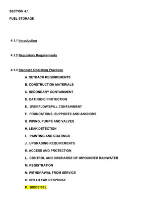
  • 37. Figure 4.3 Typical Double-Walled Underground Storage Tank
  • 38.
  • 39. Figure 4.4 Daily Fuel Consumption Log
  • 40.
  • 41. Figure 4.5 Monthly Fuel Consumption Inventory Fuel Reading Log Location: For the Month of: Tank: Day Opening Deliveries Meter Inventory Physical Variation Variation Physical Sales Should Be Inventory Today This Month Inventory