4 RELAY BOARD
•
0 likes•519 views

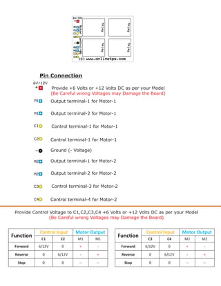
The document provides instructions for connecting pins to control two motors using a circuit board. It lists the positive and negative voltage pins, four control pins for each motor, and the motor output pins. It specifies providing either +6V or +12V DC power depending on the model and warns that incorrect voltages can damage the board. A table shows how to provide control voltages to the pins to operate each motor in forward, reverse, or stop modes.
Recommended

Recommended
More Related Content
What's hot
What's hot (13)
Similar to 4 RELAY BOARD
Similar to 4 RELAY BOARD (20)
Recently uploaded
Recently uploaded (20)
4 RELAY BOARD
- 1. Pin Connection Provide +6 Volts or +12 Volts DC as per your Model (Be Careful wrong Voltages may Damage the Board) Output terminal-1 for Motor-1 Output terminal-2 for Motor-1 Control terminal-1 for Motor-1 Control terminal-1 for Motor-1 Ground (- Voltage) Output terminal-1 for Motor-2 Output terminal-2 for Motor-2 Control terminal-3 for Motor-2 Control terminal-4 for Motor-2 Provide Control Voltage to C1,C2,C3,C4 +6 Volts or +12 Volts DC as per your Model (Be Careful wrong Voltages may Damage the Board) Control Input Motor Output Control Input Motor Output Function C1 C2 M1 M1 Function C3 C4 M2 M2 Forward 6/12V 0 + - Forward 6/12V 0 + - Reverse 0 6/12V - + Reverse 0 6/12V - + Stop 0 0 -- -- Stop 0 0 -- --