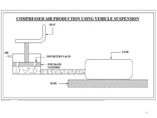
Department of Mechanical Engineering
“COMPRESSED AIR PRODUCTION USING VEHICLE
SUSPENSION”
1
DEPARTMENT OF MECHANICAL
ENGINEERING
VISION
• To provide quality education of international standards in Mechanical Engineering
and promote professionalism with ethical values, to work in a team and to face
global challenges.
MISSION
• To provide an education that builds a solid foundation in Mechanical Engineering.
• To prepare graduates for employment, higher education and enable a lifelong
growth in their profession.
• To develop good communication, leadership and entrepreneurship skills to enable
good knowledge transfer .
• To inculcate world class research program in Mechanical Engineering. 2
CONTENTS
1. Introduction
2. History
3. Objectives
4. Why pneumatics
5. Main Components
6. Components and description
7. Working principle
8. Applications
9. Advantages
10.Disadvantages
11.Conclusion
12.References 3
INTRODUCTION
•Man has needed and used energy at an increasing rate for his sustenance and well
being ever since he came on the earth a few million years ago.
•Primitive man required energy primarily in the form of food. He derived this by eating
plants or animals, which he hunted. Subsequently he discovered fire and his energy
needs increased as he started.
•To make use of wood and other bio mass to supply the energy needs for cooking as
well as for keeping himself warm. With the passage of time, man started to cultivate
land for agriculture.
•With further demand for energy, man began to use the wind for sailing ships and for
driving windmills, and the force of falling water to turn water wheels.
•Till this time, it would not be wrong to say that the sun was supplying all the energy
needs of man either directly or indirectly and that man was using only renewable
sources of energy.
4
HISTORY
• Compressed air has been used since the 19th century to power mine
locomotives and trams in cities such as Paris (via a central, city-
level, compressed air energy distribution system), and was previously the basis
of naval torpedo propulsion.
• During the construction of the Gotthardbahn
from 1872 to 1882, pneumatic locomotives
were used in the construction of the Gotthard
Rail Tunnel and other tunnels of the Gotthardbahn.
• In 1903, the Liquid Air Company located in London England manufactured a
number of compressed-air and liquefied-air cars. The major problem with these
cars and all compressed-air cars is the lack of torque produced by the "engines"
and the cost of compressing the air.
• Recently several companies have started to develop compressed air cars.
although none has been released to the public, or been tested by third parties.
5
OBJECTIVES
1. To produce non- conventional energy using vehicle jerk.
2. Use the wastage vehicle energy to produce compressed air.
3. Eco-Friendly. Not produce CO₂ as it's not use battery.
6
WHY PNEUMATICS?
• Fuel Crisis
• Cost of Gasoline
• Abundant Usage of Automobile
• Air is abundantly available in nature
• Cheaper, Safer, more flexible, and more reliable than other forms of energy
7
MAIN COMPONENTS
The important components of our project are,
•Pneumatic single acting cylinder
•Quick exhaust valve
•Spring arrangement
•Air collecting tank
•Non-return valve
8
COMPONENTS AND DESCRIPTION
RECIPROCATING COMPRESSOR:
•The cylinder is a Single acting
cylinder, which means that the air pressure
operates forward and spring returns backward.
• Force required for the forward stroke is given by the suspension action.
•The suspension action is given by the pneumatic cylinder. The compressed air is
allowed to flow through the non return valve.
9
 QUICK EXHAUST VALVE :
Any excess air in the air tank is flowed out automatically through the
quick exhaust valve.
 SPRING ARRANGEMENT
• The automobile chassis is mounted on the axles not direct but through some
form of springs.
• This is done to isolate the vehicle body from the road shocks which may
be in the form of bounce, pitch, roll or sway.
• These tendencies give rise to an uncomfortable ride and also cause
additional stress in the automobile frame and body. A Springing device
must be a compromise between flexibility and stiffness.
• If it is more rigid, it will not absorb road shocks efficiently and if it is more
flexible it will continue to vibrate even after the bump has passed so we
must have sufficient damping of the spring to prevent excessive flexing.
10
 AIR COLLECTING TANK:
The compressed air from the
compressor is collected through
non return valve by a pipe line system
and stored.
 NON-RETURN VALVE:
• This valve is used to speed up the piston movement and also it acts as an one – way
restriction valve which means that the air can pass through only one way and it
can’t return back.
• By using this valve the time consumption is reduced because of the faster movement
of the piston.
11
WORKING PRINCIPLE
•The complete diagram of the compressed air production using vehicle suspensor is
given below.
•When the vehicle runs on the irregular roads then the wheel goes to up and down
motion.
•The pushing power is converted into compressed air energy by proper driving
arrangement. The pneumatic single acting Cylinder is used for this purpose.
•Thus the piston inside the cylinder creates the internal pressure which results in
storage of air to the tank at certain pressure.
•The spring arrangement is fixed at the outside of the pneumatic cylinder. The spring
is used to return the inclined L-angle window in same position by releasing the load.
•This pressurized air from the pneumatic cylinder is collected and saved inside the
tank.
•The outlet of tank consists of valves which are used to supply the air to other
pneumatic applications.
• Here the non return valve is used to avoid the reversing of air flow to the
atmosphere.
12
13
APPLICATIONS
• This arrangement is slightly modified to construct in speed breaker and
foot step and this arrangement can be fixed in Schools.
• It is used in commercial vehicle to produce compressed air by which fill air
in tube.
• It's mainly use in vehicle like tractor in which jerk is more
• It's used in car for application like viper.
14
ADVANTAGES
• Air production is simply running the vehicle.
• No need fuel input and electrical power input.
• This is a non-conventional system.
• Easy to work and reduces the manual stress.
• Refueling can be done at home using an air compressor or at service
stations.
• Compressed air engines reduce the cost of vehicle production, because
there is no need to build a cooling system, spark plugs, starter motor, or
silencers
• The engine can be massively reduced in size.
• Lighter vehicles cause less damage to roads, resulting in lower
maintenance cost.
• The price of filling air powered vehicles is significantly cheaper than
petrol, diesel . If electricity is cheap, then compressing air will also be
relatively cheap
15
DISADVANTAGES
• Initial cost of this arrangement is high.
• When air expands in the engine it cools dramatically (Charles law) and
must be heated to ambient temperature using a heat exchanger.
• Conversely, when air is compressed to fill the tank it heats up, as the
stored air cools, its pressure decreases and available energy decreases.
• Refueling the compressed air container using a home or low-end
conventional air compressor may take as long as 4 hours, though
specialized equipment at service stations may fill the tanks in only 3
minutes.
• These vehicles provides more noisy while working.
16
CONCLUSION
• This paper is focused on compressed air mechanism form suspension system.
• This seminar can be very much useful for Indian conditions when we say Indian
condition that is not only because of good as well as bad roads available over here
but of also the variety of Indian geographical sites .
• when it comes to northern area there are hilly regions when it comes to south it is
plane costal area thus the requirement of a versatile vehicle is naturally in demand.
• Taking into consideration other manmade sites like road it is a well known fact
that we has one of the best as well as worst road conditions available. So this kind
of project is well worthing regarding Indian context of view.
• This concept will sure be polite one and can be used everywhere if cost of the
device is kept within everybody’s reach.
17
[1]Air Operated Vehicle by Using Compressed Air from Suspension,
Sivanantham.K , Banuchandar.N, Hariprakash.K , Jeeva.M, International
Journal of Innovative Research in Science, Engineering and Technology (An
ISO 3297: 2007 Certified Organization) Vol. 4, Special Issue 6, May 2015
[2]Regenerative Suspension System,Abhijit Lendhe, Nikhil Mangvade, Prasad
Naik, Pratik Jadhav , International Journal of Recent Research in
Interdisciplinary Sciences (IJRRIS) Vol. 2, Issue 2, pp: (30-33), Month: April
2015 - June 2015
[3]Development of mechanism for recovery of energy of suspension system,
Swapnil kamthe, Rahul kadam, Aniket dhore, Mr. Shivkumar falmari, Prof.
Subhash ghadve, Prof. Mukesh chaudhari, International journal of pure and
applied research in engineering and technology,Feb 2014; volume 2 (9): 169-
178, issn: 2319-507x
REFERENCE
18
[4]Compressed Air Production Using Vehicle Suspension, S.Vigneswari,
V.Vinodhini International Journal for Research in Applied Science &
Engineering Technology(IJRASET), Special Issue 2, October 2014 , ISSN:
2321-9653
19
THANK YOU
20

295790559-Compressed-Air-Production-Using-Vehicle-Suspension.pptx

  • 1.
    Department of MechanicalEngineering “COMPRESSED AIR PRODUCTION USING VEHICLE SUSPENSION” 1
  • 2.
    DEPARTMENT OF MECHANICAL ENGINEERING VISION •To provide quality education of international standards in Mechanical Engineering and promote professionalism with ethical values, to work in a team and to face global challenges. MISSION • To provide an education that builds a solid foundation in Mechanical Engineering. • To prepare graduates for employment, higher education and enable a lifelong growth in their profession. • To develop good communication, leadership and entrepreneurship skills to enable good knowledge transfer . • To inculcate world class research program in Mechanical Engineering. 2
  • 3.
    CONTENTS 1. Introduction 2. History 3.Objectives 4. Why pneumatics 5. Main Components 6. Components and description 7. Working principle 8. Applications 9. Advantages 10.Disadvantages 11.Conclusion 12.References 3
  • 4.
    INTRODUCTION •Man has neededand used energy at an increasing rate for his sustenance and well being ever since he came on the earth a few million years ago. •Primitive man required energy primarily in the form of food. He derived this by eating plants or animals, which he hunted. Subsequently he discovered fire and his energy needs increased as he started. •To make use of wood and other bio mass to supply the energy needs for cooking as well as for keeping himself warm. With the passage of time, man started to cultivate land for agriculture. •With further demand for energy, man began to use the wind for sailing ships and for driving windmills, and the force of falling water to turn water wheels. •Till this time, it would not be wrong to say that the sun was supplying all the energy needs of man either directly or indirectly and that man was using only renewable sources of energy. 4
  • 5.
    HISTORY • Compressed airhas been used since the 19th century to power mine locomotives and trams in cities such as Paris (via a central, city- level, compressed air energy distribution system), and was previously the basis of naval torpedo propulsion. • During the construction of the Gotthardbahn from 1872 to 1882, pneumatic locomotives were used in the construction of the Gotthard Rail Tunnel and other tunnels of the Gotthardbahn. • In 1903, the Liquid Air Company located in London England manufactured a number of compressed-air and liquefied-air cars. The major problem with these cars and all compressed-air cars is the lack of torque produced by the "engines" and the cost of compressing the air. • Recently several companies have started to develop compressed air cars. although none has been released to the public, or been tested by third parties. 5
  • 6.
    OBJECTIVES 1. To producenon- conventional energy using vehicle jerk. 2. Use the wastage vehicle energy to produce compressed air. 3. Eco-Friendly. Not produce CO₂ as it's not use battery. 6
  • 7.
    WHY PNEUMATICS? • FuelCrisis • Cost of Gasoline • Abundant Usage of Automobile • Air is abundantly available in nature • Cheaper, Safer, more flexible, and more reliable than other forms of energy 7
  • 8.
    MAIN COMPONENTS The importantcomponents of our project are, •Pneumatic single acting cylinder •Quick exhaust valve •Spring arrangement •Air collecting tank •Non-return valve 8
  • 9.
    COMPONENTS AND DESCRIPTION RECIPROCATINGCOMPRESSOR: •The cylinder is a Single acting cylinder, which means that the air pressure operates forward and spring returns backward. • Force required for the forward stroke is given by the suspension action. •The suspension action is given by the pneumatic cylinder. The compressed air is allowed to flow through the non return valve. 9
  • 10.
     QUICK EXHAUSTVALVE : Any excess air in the air tank is flowed out automatically through the quick exhaust valve.  SPRING ARRANGEMENT • The automobile chassis is mounted on the axles not direct but through some form of springs. • This is done to isolate the vehicle body from the road shocks which may be in the form of bounce, pitch, roll or sway. • These tendencies give rise to an uncomfortable ride and also cause additional stress in the automobile frame and body. A Springing device must be a compromise between flexibility and stiffness. • If it is more rigid, it will not absorb road shocks efficiently and if it is more flexible it will continue to vibrate even after the bump has passed so we must have sufficient damping of the spring to prevent excessive flexing. 10
  • 11.
     AIR COLLECTINGTANK: The compressed air from the compressor is collected through non return valve by a pipe line system and stored.  NON-RETURN VALVE: • This valve is used to speed up the piston movement and also it acts as an one – way restriction valve which means that the air can pass through only one way and it can’t return back. • By using this valve the time consumption is reduced because of the faster movement of the piston. 11
  • 12.
    WORKING PRINCIPLE •The completediagram of the compressed air production using vehicle suspensor is given below. •When the vehicle runs on the irregular roads then the wheel goes to up and down motion. •The pushing power is converted into compressed air energy by proper driving arrangement. The pneumatic single acting Cylinder is used for this purpose. •Thus the piston inside the cylinder creates the internal pressure which results in storage of air to the tank at certain pressure. •The spring arrangement is fixed at the outside of the pneumatic cylinder. The spring is used to return the inclined L-angle window in same position by releasing the load. •This pressurized air from the pneumatic cylinder is collected and saved inside the tank. •The outlet of tank consists of valves which are used to supply the air to other pneumatic applications. • Here the non return valve is used to avoid the reversing of air flow to the atmosphere. 12
  • 13.
  • 14.
    APPLICATIONS • This arrangementis slightly modified to construct in speed breaker and foot step and this arrangement can be fixed in Schools. • It is used in commercial vehicle to produce compressed air by which fill air in tube. • It's mainly use in vehicle like tractor in which jerk is more • It's used in car for application like viper. 14
  • 15.
    ADVANTAGES • Air productionis simply running the vehicle. • No need fuel input and electrical power input. • This is a non-conventional system. • Easy to work and reduces the manual stress. • Refueling can be done at home using an air compressor or at service stations. • Compressed air engines reduce the cost of vehicle production, because there is no need to build a cooling system, spark plugs, starter motor, or silencers • The engine can be massively reduced in size. • Lighter vehicles cause less damage to roads, resulting in lower maintenance cost. • The price of filling air powered vehicles is significantly cheaper than petrol, diesel . If electricity is cheap, then compressing air will also be relatively cheap 15
  • 16.
    DISADVANTAGES • Initial costof this arrangement is high. • When air expands in the engine it cools dramatically (Charles law) and must be heated to ambient temperature using a heat exchanger. • Conversely, when air is compressed to fill the tank it heats up, as the stored air cools, its pressure decreases and available energy decreases. • Refueling the compressed air container using a home or low-end conventional air compressor may take as long as 4 hours, though specialized equipment at service stations may fill the tanks in only 3 minutes. • These vehicles provides more noisy while working. 16
  • 17.
    CONCLUSION • This paperis focused on compressed air mechanism form suspension system. • This seminar can be very much useful for Indian conditions when we say Indian condition that is not only because of good as well as bad roads available over here but of also the variety of Indian geographical sites . • when it comes to northern area there are hilly regions when it comes to south it is plane costal area thus the requirement of a versatile vehicle is naturally in demand. • Taking into consideration other manmade sites like road it is a well known fact that we has one of the best as well as worst road conditions available. So this kind of project is well worthing regarding Indian context of view. • This concept will sure be polite one and can be used everywhere if cost of the device is kept within everybody’s reach. 17
  • 18.
    [1]Air Operated Vehicleby Using Compressed Air from Suspension, Sivanantham.K , Banuchandar.N, Hariprakash.K , Jeeva.M, International Journal of Innovative Research in Science, Engineering and Technology (An ISO 3297: 2007 Certified Organization) Vol. 4, Special Issue 6, May 2015 [2]Regenerative Suspension System,Abhijit Lendhe, Nikhil Mangvade, Prasad Naik, Pratik Jadhav , International Journal of Recent Research in Interdisciplinary Sciences (IJRRIS) Vol. 2, Issue 2, pp: (30-33), Month: April 2015 - June 2015 [3]Development of mechanism for recovery of energy of suspension system, Swapnil kamthe, Rahul kadam, Aniket dhore, Mr. Shivkumar falmari, Prof. Subhash ghadve, Prof. Mukesh chaudhari, International journal of pure and applied research in engineering and technology,Feb 2014; volume 2 (9): 169- 178, issn: 2319-507x REFERENCE 18
  • 19.
    [4]Compressed Air ProductionUsing Vehicle Suspension, S.Vigneswari, V.Vinodhini International Journal for Research in Applied Science & Engineering Technology(IJRASET), Special Issue 2, October 2014 , ISSN: 2321-9653 19
  • 20.