
More Related Content
What's hot
What's hot (20)
Similar to 2002 toyota highlander service repair manual
Similar to 2002 toyota highlander service repair manual (20)
More from dfjjsjekfkskemme
More from dfjjsjekfkskemme (20)
Recently uploaded
Recently uploaded (20)
2002 toyota highlander service repair manual
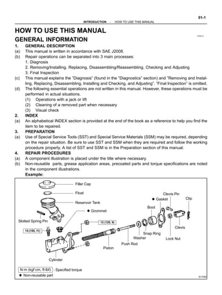
- 1. 010QH-01 N17080 Filler Cap Float Reservoir Tank z Grommet Clip Slotted Spring Pin : Specified torque z Non-reusable part Cylinder Piston Push Rod Washer Snap Ring Boot z Gasket Lock Nut Clevis Pin Clevis N·m (kgf·cm, ft·lbf) 12 (120, 9) 15 (155, 11) -INTRODUCTION HOW TO USE THIS MANUAL 01-1 1Author : Date : 2005 HIGHLANDER REPAIR MANUAL (RM1144U) HOW TO USE THIS MANUAL GENERAL INFORMATION 1. GENERAL DESCRIPTION (a) This manual is written in accordance with SAE J2008. (b) Repair operations can be separated into 3 main processes: 1. Diagnosis 2. Removing/Installing, Replacing, Disassembling/Reassembling, Checking and Adjusting 3. Final Inspection (c) This manual explains the ”Diagnosis” (found in the ”Diagnostics” section) and ”Removing and Instal- ling, Replacing, Disassembling, Installing and Checking, and Adjusting”. ”Final Inspection” is omitted. (d) The following essential operations are not written in this manual. However, these operations must be performed in actual situations. (1) Operations with a jack or lift (2) Cleaning of a removed part when necessary (3) Visual check 2. INDEX (a) An alphabetical INDEX section is provided at the end of the book as a reference to help you find the item to be repaired. 3. PREPARATION (a) Use of Special Service Tools (SST) and Special Service Materials (SSM) may be required, depending on the repair situation. Be sure to use SST and SSM when they are required and follow the working procedure properly. A list of SST and SSM is in the Preparation section of this manual. 4. REPAIR PROCEDURES (a) A component illustration is placed under the title where necessary. (b) Non-reusable parts, grease application areas, precoated parts and torque specifications are noted in the component illustrations. Example:
- 2. Illustration: what to do and where Component part No. Detailed text: how to perform task Task heading: what you will be doing Set part No. INSTALL FRONT AXLE HUB BEARING D31332 B80366 01-2 -INTRODUCTION HOW TO USE THIS MANUAL 2Author : Date : 2005 HIGHLANDER REPAIR MANUAL (RM1144U) (c) Torque specifications, grease application areas, and non-reusable parts are emphasized in the proce- dures. NOTICE: There are cases where such information can only be explained by using an illustration. In these cases, all the information such as torque, oil, etc. are described in the illustration. (d) The installation procedures are the removal procedures in reverse order. However, only installation procedures requiring additional information are included. (e) Only items with key points are described in the text. What to do and other details are placed in illustra- tions next to the text. Both the text and illustrations are accompanied by standard values and notices. (f) Illustrations of similar vehicle models are sometimes used. In those cases, specific details may be dif- ferent from the actual vehicle. (g) Procedures are presented in a step-by-step format: (1) The illustration shows what to do and where to do it. (2) The task heading tells what to do. (3) The explanation text tells how to perform the task. It also has information such as specifications and warnings. Example: HINT: This format provides an experienced technician with a FAST TRACK to the necessary information. The task headings are easy to read and the text below the task heading provides detailed information. Important spec- ifications and warnings are always written in bold type. 5. SERVICE SPECIFICATIONS (a) SPECIFICATIONS are presented in bold-faced text throughout the manual. The specifications are also found in the Service Specifications section for quick reference. 6. TERMS DEFINITION CAUTION Possibility of injury to you or other people. NOTICE Possibility of damage to the components being repaired. HINT Provides additional information to help you perform repairs.
- 3. -INTRODUCTION HOW TO USE THIS MANUAL 01-3 3Author : Date : 2005 HIGHLANDER REPAIR MANUAL (RM1144U) 7. SI UNIT (a) The units used in this manual comply with the SI UNIT (International System of Units) standard. Units from the metric system and the English system are also provided. Example: Torque: 30 N⋅m (310 kgf⋅cm, 22 ft⋅lbf)
- 4. 010QI-01 D25521 A B D25520 A B C 01-4 -INTRODUCTION IDENTIFICATION INFORMATION 4Author : Date : 2005 HIGHLANDER REPAIR MANUAL (RM1144U) IDENTIFICATION INFORMATION VEHICLE IDENTIFICATION AND SERIAL NUMBERS 1. VEHICLE IDENTIFICATION NUMBER (a) The vehicle identification number is stamped on the ve- hicle identification number plate and certification label, as shown in the illustration. A: Vehicle Identification Number Plate B: Certification Label 2. ENGINE SERIAL NUMBER AND TRANSAXLE SERIAL NUMBER (a) The engine serial number is stamped on the cylinder block of the engine and the transmission serial number is stamped on the housing as shown in the illustration. A: 3MZ-FE B: 2AZ-FE C: U140E, U151E, U151F, U241E
- 5. 010QJ-02 1 2 3 46 5 D25016 -INTRODUCTION REPAIR INSTRUCTION 01-5 5Author : Date : 2005 HIGHLANDER REPAIR MANUAL (RM1144U) REPAIR INSTRUCTION PRECAUTION (b) HINTS ON OPERATIONS 1 Looks S Always wear a clean uniform. S Hat and safety shoes must be worn. 2 Vehicle protection S Prepare a grille cover, fender cover, seat cover and floor mat before starting the operation. 3 Safe operation S When working with 2 or more persons, be sure to check safety for one another. S When working with the engine running, pay attention to providing ventilation for exhaust fumes in the workshop. S If working on high temperature, high pressure, rotating, moving, or vibrating parts, wear appropriate safety equipment and take extra care not to injure yourself or others. S When jacking up the vehicle, be sure to support the specified location with a safety stand. S When lifting up the vehicle, use appropriate safety equipment. 4 Preparation of tools and measuring gauge S Before starting operation, prepare a tool stand, SST, gauge, oil, shop rag and parts for replacement. 5 Removal and installation, disassembly and assem- bly operations S Diagnose with a thorough understanding of proper procedures and of the reported problem. S Before removing the parts, check the general condition of the assembly and for deformation and damage. S When the assembly is complicated, take notes. For example, note the total number of electrical connections, bolts, or hoses removed. Add matchmarks to insure re-assembly of components in the original positions. Temporarily mark hoses and their fittings, if needed. S Clean and wash the removed parts if necessary and assemble them after a thorough check. 6 Removed parts S Place the removed parts in a separate box to avoid mixing them up with the new parts or contaminating the new parts. S As for non-reusable parts such as a gasket, an O-ring, and a self-locking nut, replace them with new ones following the instructions in this manual. S Retain the removed parts for customer inspection, if requested.
- 6. Z11554 Seal Lock Adhesive BE1367 Medium Current Fuse and High Current Fuse Equal Amperage Rating D27353D27353D27353 V35002 Illustration Symbol Part Name Abbreviation FUSE MEDIUM CURRENT FUSE HIGH CURRENT FUSE FUSE M-FUSE H-FUSE 01-6 -INTRODUCTION REPAIR INSTRUCTION 6Author : Date : 2005 HIGHLANDER REPAIR MANUAL (RM1144U) (c) JACKING UP AND SUPPORTING VEHICLE (1) Care must be taken when jacking up and supporting the vehicle. Be sure to lift and support the vehicle at the proper locations (see page 01-21 ). (d) PRECOATED PARTS (1) Precoated parts are bolts and nuts, that are coated with a seal lock adhesive at the factory. (2) If a precoated part is retightened, loosened or moved in anyway, it must be recoated with the spe- cified adhesive. (3) When reusing precoated parts, clean off the old adhesive and dry the part with compressed air. Then apply new seal lock adhesive appropriate to the bolts and nut. NOTICE: Perform the torque with the lower limit value of the torque tolerance. (4) Some seal lock agents harden slowly. You may have to wait for the seal lock agent to harden. (e) GASKETS (1) When necessary, use a sealer on gaskets to prevent leaks. (f) BOLTS, NUTS AND SCREWS (1) Carefully follow all the specifications for tightening torques. Always use a torque wrench. (g) FUSES (1) When replacing fuses, be sure that the new fuse has the correct amperage rating. DO NOT exceed the rating or use one with a lower rating.
- 7. D25786 Shape (Example) Removal/Installation Clip Remover Pliers Screwdriver Scraper Protective Tape Clip Protective Tape Remove clips from front or rear using clip remover or pliers. Remove fasteners with a clip remover or screwdriver. Remove clips with a wide scraper to prevent panel damage. -INTRODUCTION REPAIR INSTRUCTION 01-7 7Author : Date : 2005 HIGHLANDER REPAIR MANUAL (RM1144U) (h) CLIPS (1) The removal and installation methods of typical clips used in body parts are shown in the table below. HINT: If clips are damaged during a procedure, always replace the damaged clip with a new clip.
- 8. V35006 Shape (Example) Removal/Installation Removal Installation Removal Installation Removal Installation Screwdriver Screwdriver Screwdriver Clip Remover Clip Remover Clip Remover Push Push Push Small Clip Remover Remove rivet by pushing the center pin through and prying out the rivet shell. Remove rivet by unscrewing the center pin and prying out the rivet shell. Remove rivet by prying out the pin and then prying out the rivet shell. 01-8 -INTRODUCTION REPAIR INSTRUCTION 8Author : Date : 2005 HIGHLANDER REPAIR MANUAL (RM1144U)
- 9. D31750 CORRECTINCORRECT D25064 L1 L2L1 L2L1 L2L1 L2L1 L2 D02612 L2L1 L2L1 L2L1 L2L1 L2L1 D01201 -INTRODUCTION REPAIR INSTRUCTION 01-9 9Author : Date : 2005 HIGHLANDER REPAIR MANUAL (RM1144U) (i) REMOVAL AND INSTALLATION OF VACUUM HOSES (1) To disconnect vacuum hoses, pull and twist from the end of the hose. Do not pull from the middle of the hose as this may cause damage. (2) When disconnecting vacuum hoses, use tags to identify where they should be reconnected. (3) After completing the job, double check that the vac- uum hoses are properly connected. The label under the hood shows the proper layout. (4) When using a vacuum gauge, never force the hose onto a connector that is too large. Use a step-down adapter for adjustment. Once the hose has been stretched, it may leak air. (j) TORQUE WHEN USING TORQUE WRENCH WITH EX- TENSION TOOL (1) If SST or an extension tool is combined with the torque wrench to extend its length, do not tighten the torque wrench to the specified torque values in this manual. The resulting torque will be excessive. (2) Use the formula below to calculate special torque values for situations where SST or an extension tool is combined with the torque wrench. (3) Formula: T’ = T x L2/(L1 + L2) T’ Reading of torque wrench {N⋅m (kgf⋅cm, ft⋅lbf)} T Torque {N⋅m (kgf⋅cm, ft⋅lbf)} L1 Length of SST or extension tool (cm) L2 Length of torque wrench (cm)
- 10. 01-10 -INTRODUCTION REPAIR INSTRUCTION 10Author : Date : 2005 HIGHLANDER REPAIR MANUAL (RM1144U) 1. FOR VEHICLES EQUIPPED WITH SRS AIRBAG AND SEAT BELT PRETENSIONER HINT: The HIGHLANDER is equipped with a Supplemental Restraint System (SRS) and seat belt pretensioner. Failure to carry out the service operations in the correct sequence could cause the SRS to unexpectedly deploy during servicing and lead to serious injury. Furthermore, if a mistake is made when servicing the SRS, it is possible that the SRS may fail to operate properly. Before servicing (including removal or installation of parts, inspection or replacement), be sure to read the following section carefully. (a) GENERAL NOTICE (1) Malfunction symptoms of the SRS are difficult to confirm so the Diagnostic Trouble Codes (DTCs) become the most important source of information when troubleshooting. When troubleshooting the SRS, always check the DTCs before disconnecting the battery (see page 05-1215 ). (2) To avoid serious injury, servicing the SRS must be started at least 90 seconds after: S The ignition switch is turned to the LOCK position. S The negative (-) terminal cable is disconnected from the battery. (The SRS is equipped with a back-up power source. If work is started within 90 seconds of dis- connecting the negative (-) terminal cable from the battery, the SRS may deploy.) Disconnecting the negative (-) terminal cable will erase the memory of all vehicle systems. Initial- ize the systems after disconnecting/reconnecting the cable. CAUTION: Never use a back-up power source (battery or other) in an attempt to avoid erasing system memory. The back-up power source inadvertently may inadvertently power the SRS and cause it to deploy. (3) In minor collisions where the SRS does not deploy, the horn button assembly, instrument panel passenger airbag assembly, front seat airbag assembly, curtain shield airbag assembly and seat belt pretensioner should be inspected before further use of the vehicle (see pages 60-19 , 60-31 , 60-40 , 60-46 , and 61-8 ). (4) Never use SRS parts from another vehicle. When replacing parts, use new parts. (5) Before repairs, remove the airbag sensor if impacts are likely to be applied to the sensor during repairs. (6) Never disassemble and repair the airbag sensor assembly, horn button assembly, instrument panel passenger airbag assembly, front seat airbag assembly, curtain shield airbag assembly or seat belt pretensioner. (7) Replace the center airbag sensor assembly, side airbag sensor assembly, horn button assembly or the instrument panel passenger airbag assembly, front seat airbag assembly or curtain shield airbag assembly if: 1) damage has occurred from being dropped, or 2) cracks, dents or other defects in the case, bracket or connector are present. (8) Do not directly expose the airbag sensor assembly, the horn button assembly, the instrument panel passenger airbag assembly, front seat airbag assembly, the curtain shield airbag assem- bly or the seat belt pretensioner to hot air or flames. (9) Use a voltmeter/ohmmeter with high impedance (10 kΩ/V minimum) for troubleshooting electri- cal circuits. (10) Information labels are attached to the SRS components. Follow the instructions on the labels. (11) After work on the SRS is completed, check the SRS warning light (see page 05-1207 ).
- 11. D30401 Mark D25096 Example: CORRECT INCORRECT Z13950 Example: NEVER USE AN OHMMETER ON AN AIRBAG OR PRETENSIONER -INTRODUCTION REPAIR INSTRUCTION 01-1 1 11Author : Date : 2005 HIGHLANDER REPAIR MANUAL (RM1144U) (b) SPIRAL CABLE (in Combination Switch) (1) The steering wheel must be fitted correctly to the steering column with the spiral cable at the neutral position, otherwise cable disconnection and other problems may occur. Refer to page 60-26 for in- formation about correct installation of the steering wheel. (c) HORN BUTTON ASSEMBLY (with Airbag) (1) When removing the horn button assembly or handling a new horn button, it should be placed with the pad surface facing up. See illustration below. Placing the horn button with the pad surface facing down may lead to a serious accident if the airbag accidently inflates. Also, do not place anything on top of the horn button. (2) Never measure the resistance of the airbag squib. This may cause the airbag to inflate, which could cause serious injury. (3) Grease or detergents of any kind should not be applied to the steering wheel pad. (4) Store the horn button assembly in an area where the ambient temperature is below 93°C (200°F), the humidity is not high and electrical noise is not nearby. (5) When using electric welding anywhere on the vehicle, disconnect the airbag ECU connectors (4 pins). These connectors contain shorting springs. This feature reduces the possibility of the airbag or seat belt pretensioner deploying due to currents entering the squib wiring. (6) When disposing of the vehicle or the horn button assembly by itself, the airbag should be inflated using an SST before disposal (see page 60-19 ). Perform the operation in a safe place away from electrical noise.
- 12. Thank you very much for your reading. Please Click Here. Then Get COMPLETE MANUAL. NO WAITING NOTE: If there is no response to click on the link above, please download the PDF document first and then click on it.
- 13. D27522 Example: CORRECT INCORRECT Z13951 Example: NEVER USE AN OHMMETER ON AN AIRBAG OR PRETENSIONER 01-12 -INTRODUCTION REPAIR INSTRUCTION 12Author : Date : 2005 HIGHLANDER REPAIR MANUAL (RM1144U) (d) INSTRUMENT PANEL PASSENGER AIRBAG ASSY (1) Always place a removed or new instrument panel passenger airbag assembly with the airbag inflation direction facing up. Placing the airbag assembly with the airbag inflation direction facing down could cause a serious accident if the airbag inflates. (2) Never measure the resistance of the airbag squib. This may cause the airbag to inflate, which could cause serious injury. (3) Grease or detergents of any kinds should not be applied to the instrument panel passenger air- bag assembly. (4) Store the airbag assembly in an area where the ambient temperature is below 93°C (200°F), the humidity is not high and electrical noise is not nearby. (5) When using electric welding anywhere on the vehicle, disconnect the airbag ECU connectors (4 pins). These connectors contain shorting springs. This feature reduces the possibility of the airbag deploying due to currents entering the squib wiring. (6) When disposing of a vehicle or the airbag assembly unit by itself, the airbag should be deployed using SST before disposal (see page 60-31 ). Activate in a safe place away from electrical noise. (e) CURTAIN SHIELD AIRBAG ASSEMBLY (1) Always place the removed or new curtain shield airbag assembly in a clear plastic bag, and keep it in a safe place. NOTICE: Plastic bag is not re-useable. CAUTION: Never disassemble the curtain shield airbag assembly. (2) Never measure the resistance of the airbag squib. This may cause the airbag to inflate, which is very dangerous. (3) Grease should not be attached to the curtain shield airbag assembly, and the surface should not be cleared with detergents of any kind.
- 14. D31641 Example: CORRECT Clear Plastic Bag INCORRECT D30931NEVER USE AN OHMMETER ON AN AIRBAG OR PRETENSIONER -INTRODUCTION REPAIR INSTRUCTION 01-13 13Author : Date : 2005 HIGHLANDER REPAIR MANUAL (RM1144U) (4) Store the airbag assembly in an area where the ambient temperature is below 93°C (200°F), the humidity is not high and electrical noise is not nearby. (5) When using electric welding anywhere on the vehicle, disconnect the airbag ECU connectors (2 pins). These connectors contain shorting springs. This feature reduces the possibility of the airbag deploying due to currents entering the squib wiring. (6) When disposing of a vehicle or the curtain shield airbag assembly unit, the airbag should be deployed using SST before disposal (see page 60-40 ). Activate in a safe place away from electrical noise. (f) FRONT SEAT AIRBAG ASSEMBLY (1) Always place a removed or new front seat airbag assembly with the airbag inflation direction fac- ing up. Placing the airbag assembly with the airbag inflation direction facing downward could cause a serious accident if the airbag deploys. (2) Never measure the resistance of the airbag squib. This may cause the airbag to inflate, which is very dangerous. (3) Grease should not be applied to the front seat airbag assembly, and the airbag door should not be cleaned with detergents of any kind. (4) Store the airbag assembly in an area where the ambient temperature is below 93°C (200°F), the humidity is not high and electrical noise is not nearby. (5) When using electric welding anywhere on the vehicle, disconnect the airbag ECU connectors (2 pins). These connectors contain shorting springs. This feature reduces the possibility of the airbag deploying due to currents entering the squib wiring. (6) When disposing of a vehicle or the airbag assembly unit by itself, the airbag should be deployed using SST before disposal (see page 60-46 ). Activate in a safe place away from electrical noise.
- 15. D30924 Example: NEVER USE AN OHMMETER ON AN AIRBAG OR PRETENSIONER D30370 Example: NEVER USE AN OHMMETER ON AN AIRBAG OR PRETENSIONER 01-14 -INTRODUCTION REPAIR INSTRUCTION 14Author : Date : 2005 HIGHLANDER REPAIR MANUAL (RM1144U) (g) SEAT BELT PRETENSIONER (1) Never measure the resistance of the seat belt pretensioner. This may cause the seat belt preten- sioner to activate, which is very dangerous. (2) Never disassemble the seat belt pretensioner. (3) Never install the seat belt pretensioner on another vehicle. (4) Store the seat belt pretensioner in area where the ambient temperature is below 80°C (176°F), the humidity is not high and electrical noise is not nearby. (5) When using electric welding anywhere on the vehicle, disconnect the airbag ECU connectors (2 pins). These connectors contain shorting springs. This feature reduces the possibility of the airbag deploying due to currents entering the squib wiring. (6) When disposing of a vehicle or the seat belt pretensioner unit by itself, the seat belt pretensioner should be activated before disposal (see page 61-8 ). Activate in a safe place away from electri- cal noise. (7) The seat belt pretensioner is hot after being activated, so allow some time for it to cool down suffi- ciently before disposal. Never apply water to cool down the seat belt pretensioner. (8) Oil or water should not be put on the front seat outer belt, and the front seat outer belt should not be cleaned with detergents of any kind. (h) AIRBAG SENSOR ASSEMBLY (1) Never reuse an airbag sensor assembly that has been involved in a collision where the SRS has deployed. (2) The connectors to the airbag sensor assembly should be connected or disconnected with the sensor mounted on the floor. If the connectors are connected or disconnected while the airbag sensor assembly is not mounted to the floor, it could cause accidental deployment of the SRS. (3) Work must be started at least 90 seconds after the ignition switch is turned to the LOCK position and the negative (-) terminal cable is disconnected from the battery, even if only loosening the set bolts of the airbag sensor assembly.
- 16. D25080 Negative (-) Terminal D31751 INCORRECT -INTRODUCTION REPAIR INSTRUCTION 01-15 15Author : Date : 2005 HIGHLANDER REPAIR MANUAL (RM1144U) (i) WIRE HARNESS AND CONNECTOR (1) The SRS wire harness is integrated with the instrument panel wire harness assembly. All the con- nectors in the system are a standard yellow color. If the SRS wire harness becomes discon- nected or the connector becomes broken, repair or replace it. 2. ELECTRONIC CONTROL (a) REMOVAL AND INSTALLATION OF BATTERY TERMI- NAL (1) Before performing electronic work, disconnect the battery negative (-) terminal cable beforehand to prevent component and wire damage caused by accidental short circuits. (2) When disconnecting and installing the terminal cable, turn the ignition switch and lighting switch OFF and loosen the terminal nut completely. Per- form these operations without twisting or prying the terminal. Remove the battery cable from battery post. (3) Clock settings, radio settings, DTCs and other data are erased when the battery cable is removed. Be- fore removing the battery cable, record any neces- sary data. (4) When disconnecting the battery’s negative (-) ter- minal cable, re-initialize the following systems after the completion of the operation. (b) HANDLING OF ELECTRONIC PARTS (1) Do not open the cover or case of the ECU unless absolutely necessary. If the IC terminals are touched, the IC may be rendered inoperative by static electricity. (2) To disconnect electronic connectors, pull the con- nector itself, not the wires. (3) Be careful not to drop electronic components, such as sensors or relays. If they are dropped on a hard floor, they should be replaced. (4) When cleaning the engine with steam, protect the electronic components, air filter and emission-re- lated components from water. (5) Never use an impact wrench to remove or install temperature switches or temperature sensors. (6) When checking the continuity at the wire connector, insert the tester probe carefully to prevent terminals from bending.