This document provides instructions and safety precautions for servicing a 2000 Nissan Sentra. It begins with safety notices regarding working with airbags, the vehicle immobilizer system, and the fuel injection/engine control systems. It then describes how to use the service manual and read wiring diagrams. Sections provide details on inspecting connectors and terminals, performing diagnostic tests, using the Consult-II diagnostic system, and vehicle identification information. Throughout, it emphasizes being thoroughly familiar with procedures before starting any repair work.
This is the Highly Detailed factory service repair manual for the2002 NISSAN MAXIMA, this Service Manual has detailed illustrations as well as step by step instructions,It is 100 percents complete and intact. they are specifically written for the do-it-yourself-er as well as the experienced mechanic.2002 NISSAN MAXIMA Service Repair Workshop Manual provides step-by-step instructions based on the complete dis-assembly of the machine. It is this level of detail, along with hundreds of photos and illustrations, that guide the reader through each service and repair procedure. Complete download comes in pdf format which can work under all PC based windows operating system and Mac also, All pages are printable. Using this repair manual is an inexpensive way to keep your vehicle working properly.
Service Repair Manual Covers:
General Information
Maintenance
Engine Mechanical
Engine Lubrication & Cooling Systems
Engine Control System
Accelerator Control, Fuel & Exhaust Systems
Clutch
Manual Transaxle
Automatic Transaxle
Front & Rear Axle
Front & Rear Suspension
Brake System
Steering System
Restraint System
Body & Trim
Heater & Air Conditioner
Starting & Charging System
Electrical System
Alphabetical Index
File Format: PDF
Compatible: All Versions of Windows & Mac
Language: English
Requirements: Adobe PDF Reader
NO waiting, Buy from responsible seller and get INSTANT DOWNLOAD, Without wasting your hard-owned money on uncertainty or surprise! All pages are is great to have2002 NISSAN MAXIMA Service Repair Workshop Manual.
Looking for some other Service Repair Manual,please check:
https://www.aservicemanualpdf.com/
Thanks for visiting!
This is the Highly Detailed factory service repair manual for the1998 INFINITI QX4, this Service Manual has detailed illustrations as well as step by step instructions,It is 100 percents complete and intact. they are specifically written for the do-it-yourself-er as well as the experienced mechanic.1998 INFINITI QX4 Service Repair Workshop Manual provides step-by-step instructions based on the complete dis-assembly of the machine. It is this level of detail, along with hundreds of photos and illustrations, that guide the reader through each service and repair procedure. Complete download comes in pdf format which can work under all PC based windows operating system and Mac also, All pages are printable. Using this repair manual is an inexpensive way to keep your vehicle working properly.
Service Repair Manual Covers:
General Information
Maintenance
Engine Mechanical
Engine Lubrication & Cooling Systems
Engine Control System
Accelerator Control, Fuel & Exhaust Systems
Automatic Transmission
Transfer
Propeller Shaft & Differential Carrier
Front & Rear Axle
Front & Rear Suspension
Brake System
Steering System
Restraint System
Body & Trim
Heater & Air Conditioner
Starting & Charging System
Electrical System
Alphabetical Index
File Format: PDF
Compatible: All Versions of Windows & Mac
Language: English
Requirements: Adobe PDF Reader
NO waiting, Buy from responsible seller and get INSTANT DOWNLOAD, Without wasting your hard-owned money on uncertainty or surprise! All pages are is great to have1998 INFINITI QX4 Service Repair Workshop Manual.
Looking for some other Service Repair Manual,please check:
https://www.aservicemanualpdf.com/
Thanks for visiting!
This is the Highly Detailed factory service repair manual for the1999 NISSAN QUEST, this Service Manual has detailed illustrations as well as step by step instructions,It is 100 percents complete and intact. they are specifically written for the do-it-yourself-er as well as the experienced mechanic.1999 NISSAN QUEST Service Repair Workshop Manual provides step-by-step instructions based on the complete dis-assembly of the machine. It is this level of detail, along with hundreds of photos and illustrations, that guide the reader through each service and repair procedure. Complete download comes in pdf format which can work under all PC based windows operating system and Mac also, All pages are printable. Using this repair manual is an inexpensive way to keep your vehicle working properly.
Service Repair Manual Covers:
* General Information
* Maintenance
* Engine Mechanical
* Engine Lubrication & Cooling Systems
* Engine Control System
* Accelerator Control, Fuel & Exhaust Systems
* Automatic Transaxle
* Front & Rear Axle
* Front & Rear Suspension
* Brake System
* Steering System
* Restraint System
* Body & Trim
* Heater & Air Conditioner
* Starting & Charging System
* Electrical System
* Alphabetical Index
File Format: PDF
Compatible: All Versions of Windows & Mac
Language: English
Requirements: Adobe PDF Reader
NO waiting, Buy from responsible seller and get INSTANT DOWNLOAD, Without wasting your hard-owned money on uncertainty or surprise! All pages are is great to have1999 NISSAN QUEST Service Repair Workshop Manual.
Looking for some other Service Repair Manual,please check:
https://www.aservicemanualpdf.com/
Thanks for visiting!
Check the Ford OBD1 code list to find out what the codes mean on your Ford.
>> NEXT STEP: https://www.obdadvisor.com/codes/
Visit our site, and type the code in the search box. You will get more information about the code including causes, symptoms, fixes, and repair costs.
Reading and clearing the codes will become easier with a scan tool.
>> READ MORE: https://www.obdadvisor.com/ford-scan-tool/
This article shows a helpful in-depth review of the best OBD1 scan tools for your Ford. In fact, Ford-specific scanners generally perform better than universal ones, simply because they are made specifically for a particular car brand. It helps to exactly diagnose your vehicle and cut the repair cost.
An introduction to the product portfolio of temperature and process controllers, process indicators and transmitters from PMA (part of West Control Solutions)
Check the GM OBD1 code list to find out what the codes mean on your car.
>> NEXT STEP: https://www.obdadvisor.com/codes/
Visit our site, and type the code in the search box. You will get more information about the code including causes, symptoms, fixes, and repair costs.
Reading and clearing the codes will become easier with a scan tool.
>> READ MORE: https://www.obdadvisor.com/gm-scan-tool-review/
This article shows a helpful in-depth review of the 7 best OBD1 scan tools for your GM. In fact, GM-specific scanners generally perform better than universal ones, simply because they are made specifically for a particular car brand. It helps to exactly diagnose your vehicle and cut the repair cost.
The Brooks® Ar-MiteTM is a reliable, low flow metal tube flowmeter with 316L stainless steel wetted parts. The magnetically coupled indicator provides a highly reliable method of indication. This model is a practical and economical approach to low flow rate indication for high pressure and difficult to handle fluids. Optional accessories include 4-20 mA output, Needle Valve, Flow Controllers and Alarms.
Demo request dan pemesanan produk, hubungi kami di PT. Siwali Swantika, Jakarta : 021-45850618 / Surabaya : 031-8421264. Kunjungi website kami di www.siwali.com
Check the Honda OBD2 code list to find out what the codes mean on your car.
>> NEXT STEP: https://www.obdadvisor.com/codes/
Visit our site, and type the code in the search box. You will get more information about the code including causes, symptoms, fixes, and repair costs.
Reading and clearing the codes will become easier with a scan tool.
>> READ MORE: https://www.obdadvisor.com/best-honda-scan-tool-review/
This article shows a helpful in-depth review of the 8 best OBD2 scan tools for your Honda. In fact, Honda-specific scanners generally perform better than universal ones, simply because they are made specifically for a particular car brand. It helps to exactly diagnose your vehicle and cut the repair cost.
The Hallikainen Model 1354 Vapour Pressure Analyser is a completely automated process stream analyser.
Its fast response and minimal maintenance requirements put the 1354 at the forefront of your vapour pressure measurement needs.
Check the Honda OBD1 code list to find out what the codes mean on your car.
>> NEXT STEP: https://www.obdadvisor.com/codes/
Visit our site, and type the code in the search box. You will get more information about the code including causes, symptoms, fixes, and repair costs.
Reading and clearing the codes will become easier with a scan tool.
>> READ MORE: https://www.obdadvisor.com/obd1-scanner-review/
This article shows a helpful in-depth review of the 6 best OBD1 scan tools from me, an experienced auto mechanic who has used and tested all of them.
Check the GM OBD2 code list to find out what the codes mean on your car.
>> NEXT STEP: https://www.obdadvisor.com/codes/
Visit our site, and type the code in the search box. You will get more information about the code including causes, symptoms, fixes, and repair costs.
Reading and clearing the codes will become easier with a scan tool.
>> READ MORE: https://www.obdadvisor.com/gm-scan-tool-review/
This article shows a helpful in-depth review of the 7 best OBD2 scan tools for your GM. In fact, GM-specific scanners generally perform better than universal ones, simply because they are made specifically for a particular car brand. It helps to exactly diagnose your vehicle and cut the repair cost.
Ever been troubled by the blinking sign and didn’t know what to do?
Here’s a handy guide to dashboard symbols so that you’ll never be confused again!
Save them for later and save the trouble!
Core technology of Hyundai Motor Group's EV platform 'E-GMP'Hyundai Motor Group
What’s the force behind Hyundai Motor Group's EV performance and quality?
Maximized driving performance and quick charging time through high-density battery pack and fast charging technology and applicable to various vehicle types!
Discover more about Hyundai Motor Group’s EV platform ‘E-GMP’!
What Exactly Is The Common Rail Direct Injection System & How Does It WorkMotor Cars International
Learn about Common Rail Direct Injection (CRDi) - the revolutionary technology that has made diesel engines more efficient. Explore its workings, advantages like enhanced fuel efficiency and increased power output, along with drawbacks such as complexity and higher initial cost. Compare CRDi with traditional diesel engines and discover why it's the preferred choice for modern engines.
Things to remember while upgrading the brakes of your carjennifermiller8137
Upgrading the brakes of your car? Keep these things in mind before doing so. Additionally, start using an OBD 2 GPS tracker so that you never miss a vehicle maintenance appointment. On top of this, a car GPS tracker will also let you master good driving habits that will let you increase the operational life of your car’s brakes.
Why Is Your BMW X3 Hood Not Responding To Release CommandsDart Auto
Experiencing difficulty opening your BMW X3's hood? This guide explores potential issues like mechanical obstruction, hood release mechanism failure, electrical problems, and emergency release malfunctions. Troubleshooting tips include basic checks, clearing obstructions, applying pressure, and using the emergency release.
"Trans Failsafe Prog" on your BMW X5 indicates potential transmission issues requiring immediate action. This safety feature activates in response to abnormalities like low fluid levels, leaks, faulty sensors, electrical or mechanical failures, and overheating.
𝘼𝙣𝙩𝙞𝙦𝙪𝙚 𝙋𝙡𝙖𝙨𝙩𝙞𝙘 𝙏𝙧𝙖𝙙𝙚𝙧𝙨 𝙞𝙨 𝙫𝙚𝙧𝙮 𝙛𝙖𝙢𝙤𝙪𝙨 𝙛𝙤𝙧 𝙢𝙖𝙣𝙪𝙛𝙖𝙘𝙩𝙪𝙧𝙞𝙣𝙜 𝙩𝙝𝙚𝙞𝙧 𝙥𝙧𝙤𝙙𝙪𝙘𝙩𝙨. 𝙒𝙚 𝙝𝙖𝙫𝙚 𝙖𝙡𝙡 𝙩𝙝𝙚 𝙥𝙡𝙖𝙨𝙩𝙞𝙘 𝙜𝙧𝙖𝙣𝙪𝙡𝙚𝙨 𝙪𝙨𝙚𝙙 𝙞𝙣 𝙖𝙪𝙩𝙤𝙢𝙤𝙩𝙞𝙫𝙚 𝙖𝙣𝙙 𝙖𝙪𝙩𝙤 𝙥𝙖𝙧𝙩𝙨 𝙖𝙣𝙙 𝙖𝙡𝙡 𝙩𝙝𝙚 𝙛𝙖𝙢𝙤𝙪𝙨 𝙘𝙤𝙢𝙥𝙖𝙣𝙞𝙚𝙨 𝙗𝙪𝙮 𝙩𝙝𝙚 𝙜𝙧𝙖𝙣𝙪𝙡𝙚𝙨 𝙛𝙧𝙤𝙢 𝙪𝙨.
Over the 10 years, we have gained a strong foothold in the market due to our range's high quality, competitive prices, and time-lined delivery schedules.
Fleet management these days is next to impossible without connected vehicle solutions. Why? Well, fleet trackers and accompanying connected vehicle management solutions tend to offer quite a few hard-to-ignore benefits to fleet managers and businesses alike. Let’s check them out!
Comprehensive program for Agricultural Finance, the Automotive Sector, and Empowerment . We will define the full scope and provide a detailed two-week plan for identifying strategic partners in each area within Limpopo, including target areas.:
1. Agricultural : Supporting Primary and Secondary Agriculture
• Scope: Provide support solutions to enhance agricultural productivity and sustainability.
• Target Areas: Polokwane, Tzaneen, Thohoyandou, Makhado, and Giyani.
2. Automotive Sector: Partnerships with Mechanics and Panel Beater Shops
• Scope: Develop collaborations with automotive service providers to improve service quality and business operations.
• Target Areas: Polokwane, Lephalale, Mokopane, Phalaborwa, and Bela-Bela.
3. Empowerment : Focusing on Women Empowerment
• Scope: Provide business support support and training to women-owned businesses, promoting economic inclusion.
• Target Areas: Polokwane, Thohoyandou, Musina, Burgersfort, and Louis Trichardt.
We will also prioritize Industrial Economic Zone areas and their priorities.
Sign up on https://profilesmes.online/welcome/
To be eligible:
1. You must have a registered business and operate in Limpopo
2. Generate revenue
3. Sectors : Agriculture ( primary and secondary) and Automative
Women and Youth are encouraged to apply even if you don't fall in those sectors.
5 Warning Signs Your BMW's Intelligent Battery Sensor Needs AttentionBertini's German Motors
IBS monitors and manages your BMW’s battery performance. If it malfunctions, you will have to deal with an array of electrical issues in your vehicle. Recognize warning signs like dimming headlights, frequent battery replacements, and electrical malfunctions to address potential IBS issues promptly.
Symptoms like intermittent starting and key recognition errors signal potential problems with your Mercedes’ EIS. Use diagnostic steps like error code checks and spare key tests. Professional diagnosis and solutions like EIS replacement ensure safe driving. Consult a qualified technician for accurate diagnosis and repair.
In this presentation, we have discussed a very important feature of BMW X5 cars… the Comfort Access. Things that can significantly limit its functionality. And things that you can try to restore the functionality of such a convenient feature of your vehicle.
Why Isn't Your BMW X5's Comfort Access Functioning Properly Find Out Here
2000 nissan sentra service repair manual
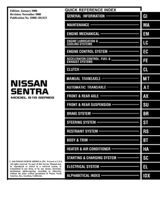
1. Edition: January 2000
Revision: November 2000
Publication No. SM0E-1B15U2
QUICK REFERENCE INDEX
All rights reserved. No part of this Service Manual may
be reproduced or stored in a retrieval system, or
transmitted in any form, or by any means, electronic,
mechanical, photo-copying, recording or otherwise,
without the prior written permission of Nissan North
America, Inc., Gardena, California.
2. FOREWORD
This manual contains maintenance and repair procedures for the
2000 NISSAN SENTRA.
In order to assure your safety and the efficient functioning of the
vehicle, this manual should be read thoroughly. It is especially
important that the PRECAUTIONS in the GI section be completely
understood before starting any repair task.
All information in this manual is based on the latest product infor-
mation at the time of publication. The right is reserved to make
changes in specifications and methods at any time without notice.
IMPORTANT SAFETY NOTICE
The proper performance of service is essential for both the safety of
the technician and the efficient functioning of the vehicle.
The service methods in this Service Manual are described in such a
manner that the service may be performed safely and accurately.
Service varies with the procedures used, the skills of the technician
and the tools and parts available. Accordingly, anyone using service
procedures, tools or parts which are not specifically recommended
by NISSAN must first be completely satisfied that neither personal
safety nor the vehicle’s safety will be jeopardized by the service
method selected.
NISSAN NORTH AMERICA, INC.
Technical Publications Department
Gardena, California
3. Attachment No.13
TID CID
P0420 01H 01H Max. 1/128
P0420 02H 81H Min. 1
P0430 03H 02H Max. 1/128
P0430 04H 82H Min. 1
P0440 05H 03H Max. 1/128mm2
P1440 05H 03H Max. 1/128mm2
EVAP control system purge flow monitoring P1447 06H 83H Min. 20mV
EVAP control system (Very small leak) P1441 07H 03H Max. 1/128mm2
P0133 09H 04H Max. 16ms
P0131 0AH 84H Min. 10mV
P0130 0BH 04H Max. 10mV
P0132 0CH 04H Max. 10mV
P0134 0DH 04H Max. 1s
P0153 11H 05H Max. 16ms
P0151 12H 85H Min. 10mV
P0150 13H 05H Max. 10mV
P0152 14H 05H Max. 10mV
P0154 15H 05H Max. 1s
P0139 19H 86H Min. 10mV/500ms
P0137 1AH 86H Min. 10mV
P0140 1BH 06H Max. 10mV
P0138 1CH 06H Max. 10mV
P0159 21H 87H Min. 10mV/500ms
P0157 22H 87H Min. 10mV
P0160 23H 07H Max. 10mV
P0158 24H 07H Max. 10mV
P0135 29H 08H Max. 20mV
P0135 2AH 88H Min. 20mV
P0155 2BH 09H Max. 20mV
P0155 2CH 89H Min. 20mV
P0141 2DH 0AH Max. 20mV
P0141 2EH 8AH Min. 20mV
P0161 2FH 0BH Max. 20mV
P0161 30H 8BH Min. 20mV
P0400 31H 8CH Min. 1
P0400 32H 8CH Min. 1
P0400 33H 8CH Min. 1
P0400 34H 8CH Min. 1
P1402 35H 0CH Max. 1
Items for which these data (test value and test limit) are displayed are the same as SRT code items.
These data (test value and test limit) are specified by Test ID (TID) and Component ID (CID) and can be dis-
played on the GST screen.
The following is the information specified in Mode 6 of SAE J1979.
The test value is a parameter used to determine whether a system/circuit diagnostic test is “OK” or “NG” while
being monitored by the ECM during self-diagnosis. The test limit is a reference value which is specified as the
Test value
(GST display)
TEST VALUE AND TEST LIMIT (GST ONLY — NOT APPLICABLE TO CONSULT-II)
Heated oxygen sensor 2 (Bank 2)
maximum or minimum value and is compared with the test value being monitored.
Test limit Conversion
CATALYST
Three way catalyst function (Bank 1)
Three way catalyst function (Bank 2)
SRT item Self-diagnostic test item DTC
HO2S HTR
Heated oxygen sensor 1 heater (Bank 1)
Heated oxygen sensor 1 heater (Bank 2)
Heated oxygen sensor 2 heater (Bank 1)
Heated oxygen sensor 2 heater (Bank 2)
EVAP SYSTEM
EVAP control system (Small leak)
EGR SYSTEM EGR function
HO2S
Heated oxygen sensor 1 (Bank 1)
Heated oxygen sensor 1 (Bank 2)
Heated oxygen sensor 2 (Bank 1)
QG18DE (Except CALIF. CA)
4. Attachment No.14
TID CID
P0420 01H 01H Max. 1/128
P0420 02H 81H Max. 1
P0440 05H 03H Max. 1/128mm2
P1440 05H 03H Max. 1/128mm2
EVAP control system purge flow monitoring P1447 06H 83H Min. 20mV
P1273 43H 0EH Max. 0.002
P1274 44H 8EH Min. 0.002
P1275 45H 8EH Min. 0.004
P0139 19H 86H Min. 10mV/500ms
P0137 1AH 86H Min. 10mV
P0140 1BH 06H Max. 10mV
P0138 1CH 06H Max. 10mV
P0145 61H 92H Min. 10mV/500ms
P0144 62H 92H Min. 10mV
P0143 63H 12H Max. 10mV
P0146 64H 12H Max. 10mV
P1277 57H 04H Max. 5mV
P1277 58H 04H Min. 5mV
P0141 2DH 0AH Max. 20mV
P0141 2EH 8AH Min. 20mV
P0147 71H 14H Max. 20mV
P0147 72H 94H Min. 20mV
P0400 31H 8CH Min. 1
P0400 32H 8CH Min. 1
P0400 33H 8CH Min. 1
P0400 34H 8CH Min. 1
P1402 35H 0CH Max. 1
TEST VALUE AND TEST LIMIT (GST ONLY — NOT APPLICABLE TO CONSULT-II)
The following is the information specified in Mode 6 of SAE J1979.
The test value is a parameter used to determine whether a system/circuit diagnostic test is “OK” or “NG” while
being monitored by the ECM during self-diagnosis. The test limit is a reference value which is specified as the
maximum or minimum value and is compared with the test value being monitored.
Items for which these data (test value and test limit) are displayed are the same as SRT code items.
These data (test value and test limit) are specified by Test ID (TID) and Component ID (CID) and can be dis-
played on the GST screen.
SRT item Self-diagnostic test item DTC
Test value
(GST display) Test limit Conversion
CATALYST Three way catalyst function
EVAP SYSTEM
EVAP control system (Small leak)
HO2S
A/F sensor 1
Heated oxygen sensor 2
Heated oxygen sensor 3
HO2S HTR
A/F sensor 1 heater
Heated oxygen sensor 2 heater
Heated oxygen sensor 3 heater
EGR SYSTEM EGR function
QG18DE (CALIF. CA)
5. Attachment No.15
TID CID
P0420 01H 01H Max. 1/128
P0420 02H 81H Min. 1
P0440 05H 03H Max. 1/128mm2
P1440 05H 03H Max. 1/128mm2
EVAP control system purge flow monitoring P1447 06H 83H Min. 20mV
P0133 09H 04H Max. 16ms
P0131 0AH 84H Min. 10mV
P0130 0BH 04H Max. 10mV
P0132 0CH 04H Max. 10mV
P0134 0DH 04H Max. 1s
P0139 19H 86H Min. 10mV/500ms
P0137 1AH 86H Min. 10mV
P0140 1BH 06H Max. 10mV
P0138 1CH 06H Max. 10mV
P0135 29H 08H Max. 20mV
P0135 2AH 88H Min. 20mV
P0141 2DH 0AH Max. 20mV
P0141 2EH 8AH Min. 20mV
P0400 31H 8CH Min. 1
P0400 32H 8CH Min. 1
P0400 33H 8CH Min. 1
P0400 34H 8CH Min. 1
P1402 35H 0CH Max. 1
TEST VALUE AND TEST LIMIT (GST ONLY — NOT APPLICABLE TO CONSULT-II)
The following is the information specified in Mode 6 of SAE J1979.
The test value is a parameter used to determine whether a system/circuit diagnostic test is “OK” or “NG” while
being monitored by the ECM during self-diagnosis. The test limit is a reference value which is specified as the
maximum or minimum value and is compared with the test value being monitored.
Items for which these data (test value and test limit) are displayed are the same as SRT code items.
These data (test value and test limit) are specified by Test ID (TID) and Component ID (CID) and can be dis-
played on the GST screen.
SRT item Self-diagnostic test item DTC
Test value
(GST display) Test limit Conversion
CATALYST Three way catalyst function
EVAP SYSTEM
EVAP control system (Small leak)
HO2S
Heated oxygen sensor 1
Heated oxygen sensor 2
HO2S HTR
Heated oxygen sensor 1 heater
Heated oxygen sensor 2 heater
EGR SYSTEM EGR function
SR20DE
6. GENERAL INFORMATION
SECTION GI
CONTENTS
PRECAUTIONS ...............................................................3
Precautions..................................................................3
SUPPLEMENTAL RESTRAINT SYSTEM (SRS)
″AIR BAG″ AND ″SEAT BELT PRE-TENSIONER″ ........3
PRECAUTIONS FOR NVIS (NISSAN VEHICLE
IMMOBILIZER SYSTEM - NATS) (IF SO
EQUIPPED)...............................................................3
GENERAL PRECAUTIONS.........................................4
PRECAUTIONS FOR MULTIPORT FUEL
INJECTION SYSTEM OR ENGINE CONTROL
SYSTEM ...................................................................6
PRECAUTIONS FOR THREE WAY CATALYST ...........6
PRECAUTIONS FOR HOSES.....................................7
PRECAUTIONS FOR ENGINE OILS ...........................7
PRECAUTIONS FOR FUEL........................................8
PRECAUTIONS FOR AIR CONDITIONING ..................8
HOW TO USE THIS MANUAL........................................9
HOW TO READ WIRING DIAGRAMS..........................11
Sample/Wiring Diagram - EXAMPL - ........................11
OPTIONAL SPLICE..................................................12
CONTROL UNIT TERMINALS AND REFERENCE
VALUE CHART........................................................13
Description.................................................................14
CONNECTOR SYMBOLS .........................................16
HARNESS INDICATION ...........................................17
COMPONENT INDICATION......................................17
SWITCH POSITIONS ...............................................17
DETECTABLE LINES AND NON-DETECTABLE
LINES .....................................................................18
MULTIPLE SWITCH.................................................19
REFERENCE AREA.................................................20
HOW TO CHECK TERMINAL.......................................22
Connector and Terminal Pin Kit.................................22
How to Probe Connectors .........................................22
PROBING FROM HARNESS SIDE............................22
PROBING FROM TERMINAL SIDE ...........................22
How to Check Enlarged Contact Spring of
Terminal .....................................................................23
Waterproof Connector Inspection..............................24
RUBBER SEAL INSPECTION...................................24
WIRE SEAL INSPECTION........................................24
Terminal Lock Inspection...........................................24
HOW TO PERFORM EFFICIENT DIAGNOSES
FOR AN ELECTRICAL INCIDENT ...............................25
Work Flow..................................................................25
Incident Simulation Tests...........................................26
INTRODUCTION......................................................26
VEHICLE VIBRATION ..............................................26
HEAT SENSITIVE....................................................27
FREEZING ..............................................................27
WATER INTRUSION ................................................28
ELECTRICAL LOAD.................................................28
COLD OR HOT START UP.......................................28
Circuit Inspection .......................................................28
INTRODUCTION......................................................28
TESTING FOR ″OPENS″ IN THE CIRCUIT ................29
TESTING FOR ″SHORTS″ IN THE CIRCUIT..............30
GROUND INSPECTION ...........................................31
VOLTAGE DROP TESTS..........................................31
CONTROL UNIT CIRCUIT TEST ...............................33
HOW TO FOLLOW TROUBLE DIAGNOSES...............35
How to Follow Test Groups in Trouble Diagnoses....36
Key to Symbols Signifying Measurements or
Procedures.................................................................37
CONSULT-II CHECKING SYSTEM...............................39
Function and System Application ..............................39
Nickel Metal Hydride Battery Replacement...............39
Checking Equipment..................................................40
CONSULT-II Data Link Connector (DLC) Circuit ......41
INSPECTION PROCEDURE .....................................41
IDENTIFICATION INFORMATION ................................42
Model Variation..........................................................42
Identification Number.................................................43
VEHICLE IDENTIFICATION NUMBER
ARRANGEMENT .....................................................43
F.M.V.S.S. CERTIFICATION LABEL...........................44
ENGINE SERIAL NUMBER.......................................44
AUTOMATIC TRANSAXLE NUMBER ........................45
MANUAL TRANSAXLE NUMBER..............................45
Dimensions ................................................................45
Wheels & Tires ..........................................................45
MA
EM
LC
EC
FE
CL
MT
AT
AX
SU
BR
ST
RS
BT
HA
SC
EL
IDX
7. LIFTING POINTS AND TOW TRUCK TOWING ...........46
Preparation ................................................................46
SPECIAL SERVICE TOOLS ......................................46
Board-on Lift ..............................................................46
Garage Jack and Safety Stand .................................47
2-pole Lift...................................................................48
Tow Truck Towing ......................................................49
VEHICLE RECOVERY (FREEING A STUCK
VEHICLE)................................................................49
TIGHTENING TORQUE OF STANDARD BOLTS ........50
SAE J1930 TERMINOLOGY LIST ................................51
SAE J1930 Terminology List .....................................51
CONTENTS (Cont’d)
GI-2
8. Precautions NIGI0001
Observe the following precautions to ensure safe and proper
servicing. These precautions are not described in each indi-
vidual section.
SGI646
SUPPLEMENTAL RESTRAINT SYSTEM (SRS) “AIR
BAG” AND “SEAT BELT PRE-TENSIONER” NIGI0001S01
The Supplemental Restraint System such as “AIR BAG” and “SEAT
BELT PRE-TENSIONER” used along with a seat belt, helps to
reduce the risk or severity of injury to the driver and front passen-
ger for certain types of collision. The SRS system composition
which is available to NISSAN MODEL B15 is as follows:
¼ For a frontal collision
The Supplemental Restraint System consists of driver air bag
module (located in the center of the steering wheel), front pas-
senger air bag module (located on the instrument panel on
passenger side), front seat belt pre-tensioners, a diagnosis
sensor unit, warning lamp, wiring harness and spiral cable.
¼ For a side collision
The Supplemental Restraint System consists of front side air
bag module (located in the outer side of front seat), side air bag
(satellite) sensor, diagnosis sensor unit (one of components of
air bags for a frontal collision), wiring harness, warning lamp
(one of components of air bags for a frontal collision).
Information necessary to service the system safely is included in
the RS section of this Service Manual.
WARNING:
¼ To avoid rendering the SRS inoperative, which could
increase the risk of personal injury or death in the event
of a collision which would result in air bag inflation, all
maintenance should be performed by an authorized NIS-
SAN dealer.
¼ Improper maintenance, including incorrect removal and
installation of the SRS, can lead to personal injury caused
by unintentional activation of the system. For removal of
Spiral Cable and Air Bag Module, see the RS section.
¼ Do not use electrical test equipment on any circuit related
to the SRS unless instructed to in this Service Manual.
Spiral cable and wiring harnesses covered with yellow
insulation tape either just before the harness connectors
or for the complete harness are related to the SRS.
PRECAUTIONS FOR NVIS (NISSAN VEHICLE
IMMOBILIZER SYSTEM — NATS) (IF SO EQUIPPED)NIGI0001S10
NVIS (NATS) will immobilize the engine if someone tries to start it
without the registered NVIS (NATS) key.
Both of the originally supplied ignition key IDs are NVIS (NATS)
registered.
The security indicator is located on the instrument panel. The indi-
cator blinks when the ignition switch is in the “OFF” or “ACC” posi-
tion. Therefore, NVIS (NATS) warns outsiders that the vehicle is
equipped with the anti-theft system.
MA
EM
LC
EC
FE
CL
MT
AT
AX
SU
BR
ST
RS
BT
HA
SC
EL
IDX
PRECAUTIONS
Precautions
GI-3
9. ¼ When NVIS (NATS) detects a malfunction, the security indica-
tor lamp lights up while ignition switch is in “ON” position.
This indicates that the system is not functioning, and prompt
service is required.
¼ When servicing NVIS (NATS) (trouble diagnoses, system ini-
tialization and additional registration of other NVIS (NATS) igni-
tion key IDs), CONSULT-II hardware and CONSULT-II NVIS
(NATS) software is necessary.
Refer to CONSULT-II operation manual, NVIS (NATS) for the
procedures of NVIS (NATS) initialization and NVIS (NATS)
ignition key ID registration.
The CONSULT-II NVIS (NATS) software (program card and
operation manual) must be kept strictly confidential to main-
tain the integrity of the anti-theft function.
¼ When servicing NVIS (NATS) (trouble diagnoses, system ini-
tialization and additional registration of other NVIS (NATS) igni-
tion key IDs), it may be necessary to re-register original key
identification. Therefore, be sure to receive all keys from the
vehicle owner. A maximum of five key IDs can be registered
into NVIS (NATS).
¼ If the engine fails to start the first time using the NVIS (NATS)
key, start as follows.
a) Leave the ignition key in “ON” position for approximately 5
seconds.
b) Turn ignition key to “OFF” or “LOCK” position and wait approxi-
mately 5 seconds.
c) Repeat step a and b again.
d) Restart the engine while keeping the key separate from any
others on key-chain.
SGI285
GENERAL PRECAUTIONS NIGI0001S03
¼ Do not operate the engine for an extended period of time
without proper exhaust ventilation.
Keep the work area well ventilated and free of any inflammable
materials. Special care should be taken when handling any
inflammable or poisonous materials, such as gasoline, refrig-
erant gas, etc. When working in a pit or other enclosed area,
be sure to properly ventilate the area before working with haz-
ardous materials.
Do not smoke while working on the vehicle.
SGI231
¼ Before jacking up the vehicle, apply wheel chocks or other tire
blocks to the wheels to prevent the vehicle from moving. After
jacking up the vehicle, support the vehicle weight with safety
stands at the points designated for proper lifting before work-
ing on the vehicle.
These operations should be done on a level surface.
¼ When removing a heavy component such as the engine or
transaxle, be careful not to lose your balance and drop them.
Also, do not allow them to strike adjacent parts, especially the
brake tubes and master cylinder.
PRECAUTIONS
Precautions (Cont’d)
GI-4
10. SEF289H
¼ Before starting repairs which do not require battery power:
Turn off ignition switch.
Disconnect the negative battery terminal.
SGI233
¼ To prevent serious burns:
Avoid contact with hot metal parts.
Do not remove the radiator cap when the engine is hot.
SGI234
¼ Before servicing the vehicle:
Protect fenders, upholstery and carpeting with appropriate cov-
ers.
Take caution that keys, buckles or buttons do not scratch paint.
¼ Clean all disassembled parts in the designated liquid or solvent
prior to inspection or assembly.
¼ Replace oil seals, gaskets, packings, O-rings, locking washers,
cotter pins, self-locking nuts, etc. with new ones.
¼ Replace inner and outer races of tapered roller bearings and
needle bearings as a set.
¼ Arrange the disassembled parts in accordance with their
assembled locations and sequence.
¼ Do not touch the terminals of electrical components which use
microcomputers (such as ECMs/PCMs).
Static electricity may damage internal electronic components.
¼ After disconnecting vacuum or air hoses, attach a tag to indi-
cate the proper connection.
¼ Use only the fluids and lubricants specified in this manual.
¼ Use approved bonding agent, sealants or their equivalents
when required.
¼ Use tools and recommended special tools where specified for
safe and efficient service repairs.
¼ When repairing the fuel, oil, water, vacuum or exhaust
systems, check all affected lines for leaks.
¼ Dispose of drained oil or the solvent used for cleaning parts in
an appropriate manner.
MA
EM
LC
EC
FE
CL
MT
AT
AX
SU
BR
ST
RS
BT
HA
SC
EL
IDX
PRECAUTIONS
Precautions (Cont’d)
GI-5
11. Do not attempt to top off the fuel tank after the fuel pump nozzle
shuts off automatically. Continued refueling may cause fuel
overflow, resulting in fuel spray and possibly a fire.
WARNING:
To prevent ECM [QG18DE (Calif. CA Model) and SR20DE]/PCM
[QG18DE (except Calif. CA Model)] from storing the diagnos-
tic trouble codes, do not carelessly disconnect the harness
connectors which are related to the engine control system and
TCM (Transmission Control Module) [QG18DE (Calif. CA
Model) and SR20DE]/PCM [QG18DE (except Calif. CA Model)]
system. The connectors should be disconnected only when
working according to the WORK FLOW of TROUBLE DIAG-
NOSES in EC and AT sections.
SGI787
PRECAUTIONS FOR MULTIPORT FUEL INJECTION
SYSTEM OR ENGINE CONTROL SYSTEM NIGI0001S04
¼ Before connecting or disconnecting any harness connector for
the multiport fuel injection system or ECM/PCM:
Turn ignition switch to “OFF” position.
Disconnect negative battery terminal.
Otherwise, there may be damage to ECM/PCM.
¼ Before disconnecting pressurized fuel line from fuel pump to
injectors, be sure to release fuel pressure.
¼ Be careful not to jar components such as ECM/PCM and mass
air flow sensor.
PRECAUTIONS FOR THREE WAY CATALYST NIGI0001S05
If a large amount of unburned fuel flows into the catalyst, the cata-
lyst temperature will be excessively high. To prevent this, follow the
instructions below:
¼ Use unleaded gasoline only. Leaded gasoline will seriously
damage the three way catalyst.
¼ When checking for ignition spark or measuring engine
compression, make tests quickly and only when necessary.
¼ Do not run engine when the fuel tank level is low, otherwise the
engine may misfire, causing damage to the catalyst.
Do not place the vehicle on flammable material. Keep flammable
material off the exhaust pipe and the three way catalyst.
PRECAUTIONS
Precautions (Cont’d)
GI-6
12. SMA019D
PRECAUTIONS FOR HOSES NIGI0001S06
Hose Removal and Installation NIGI0001S0601
¼ To prevent damage to rubber hose, do not pry off rubber hose
with tapered tool or screwdriver.
SMA020D
¼ To reinstall the rubber hose securely, make sure of hose inser-
tion length and clamp orientation. (If tube is equipped with
hose stopper, insert rubber hose into tube until it butts up
against hose stopper.)
SMA021D
Hose Clamping NIGI0001S0602
¼ If old rubber hose is re-used, install hose clamp in its original
position (at the indentation where the old clamp was). If there
is a trace of tube bulging left on the old rubber hose, align
rubber hose at that position.
¼ Discard old clamps; replace with new ones.
SMA022D
¼ After installing plate clamps, apply force to them in the direc-
tion of the arrow, tightening rubber hose equally all around.
PRECAUTIONS FOR ENGINE OILS NIGI0001S07
Prolonged and repeated contact with used engine oil may cause
skin cancer. Try to avoid direct skin contact with used oil.
If skin contact is made, wash thoroughly with soap or hand cleaner
as soon as possible.
Health Protection Precautions NIGI0001S0701
¼ Avoid prolonged and repeated contact with oils, particularly
used engine oils.
¼ Wear protective clothing, including impervious gloves where
practicable.
MA
EM
LC
EC
FE
CL
MT
AT
AX
SU
BR
ST
RS
BT
HA
SC
EL
IDX
PRECAUTIONS
Precautions (Cont’d)
GI-7
13. ¼ Do not put oily rags in pockets.
¼ Avoid contaminating clothes, particularly underclothing, with
oil.
¼ Heavily soiled clothing and oil-impregnated footwear should
not be worn. Overalls must be cleaned regularly.
¼ First Aid treatment should be obtained immediately for open
cuts and wounds.
¼ Use barrier creams, applying them before each work period, to
help the removal of oil from the skin.
¼ Wash with soap and water to ensure all oil is removed (skin
cleansers and nail brushes will help). Preparations containing
lanolin replace the natural skin oils which have been removed.
¼ Do not use gasoline, kerosine, diesel fuel, gas oil, thinners or
solvents for cleaning skin.
¼ If skin disorders develop, obtain medical advice without delay.
¼ Where practicable, degrease components prior to handling.
¼ Where there is a risk of eye contact, eye protection should be
worn, for example, chemical goggles or face shields; in addi-
tion an eye wash facility should be provided.
Environmental Protection Precautions NIGI0001S0702
Burning used engine oil in small space heaters or boilers can be
recommended only for units of approved design. The heating sys-
tem must meet the requirements of HM Inspectorate of Pollution for
small burners of less than 0.4 MW. If in doubt, check with the
appropriate local authority and/or manufacturer of the approved
appliance.
Dispose of used oil and used oil filters through authorized waste
disposal contractors to licensed waste disposal sites, or to the
waste oil reclamation trade. If in doubt, contact the local authority
for advice on disposal facilities.
It is illegal to pour used oil on to the ground, down sewers or drains,
or into water courses.
The regulations concerning the pollution vary between
regions.
PRECAUTIONS FOR FUEL NIGI0001S08
Use unleaded gasoline with an octane rating of at least 87 AKI
(Anti-Knock Index) number (research octane number 91).
CAUTION:
Do not use leaded gasoline. Using leaded gasoline will dam-
age the three way catalyst.
Using a fuel other than that specified could adversely affect
the emission control devices and systems, and could also
affect the warranty coverage validity.
PRECAUTIONS FOR AIR CONDITIONING NIGI0001S09
Use an approved refrigerant recovery unit any time the air condi-
tioning system must be discharged. Refer to HA-61, “HFC-134a
(R-134a) Service Procedure” for specific instructions.
PRECAUTIONS
Precautions (Cont’d)
GI-8
14. Thank you very much for
your reading. Please Click
Here. Then Get COMPLETE
MANUAL. NO WAITING
NOTE:
If there is no response to
click on the link above,
please download the PDF
document first and then
click on it.
15. NIGI0002
¼ ALPHABETICAL INDEX is provided at the end of this manual so that you can rapidly find the item and
page you are searching for.
¼ A QUICK REFERENCE INDEX, a black tab (e.g. ) is provided on the first page. You can quickly find
the first page of each section by matching it to the section’s black tab.
¼ THE CONTENTS are listed on the first page of each section.
¼ THE TITLE is indicated on the upper portion of each page and shows the part or system.
¼ THE PAGE NUMBER of each section consists of two letters which designate the particular section and a
number (e.g. “BR-5”).
¼ THE LARGE ILLUSTRATIONS are exploded views (See below.) and contain tightening torques, lubrica-
tion points, section number of the PARTS CATALOG (e.g. SEC. 440) and other information necessary to
perform repairs.
The illustrations should be used in reference to service matters only. When ordering parts, refer to the
appropriate PARTS CATALOG.
SBR364AC
¼ THE SMALL ILLUSTRATIONS show the important steps such as inspection, use of special tools, knacks
of work and hidden or tricky steps which are not shown in the previous large illustrations.
Assembly, inspection and adjustment procedures for the complicated units such as the automatic transaxle
or transmission, etc. are presented in a step-by-step format where necessary.
¼ The UNITS given in this manual are primarily expressed as the SI UNIT (International System of Unit),
and alternatively expressed in the metric system and in the yard/pound system.
“Example”
Tightening torque:
59 - 78 N·m (6.0 - 8.0 kg-m, 43 - 58 ft-lb)
¼ TROUBLE DIAGNOSES are included in sections dealing with complicated components.
¼ SERVICE DATA AND SPECIFICATIONS are contained at the end of each section for quick reference of
data.
¼ The following SYMBOLS AND ABBREVIATIONS are used:
MA
EM
LC
EC
FE
CL
MT
AT
AX
SU
BR
ST
RS
BT
HA
SC
EL
IDX
HOW TO USE THIS MANUAL
GI-9
16. SYMBOL ABBREVIATION SYMBOL ABBREVIATION
Tightening torque
2WD
2-Wheel Drive
Should be lubricated with grease. Unless
otherwise indicated, use recommended multi-
purpose grease
A/C
Air Conditioner
Should be lubricated with oil P/S Power Steering
Sealing point SST Special Service Tools
Checking point SAE Society of Automotive Engineers, Inc.
Always replace after every disassembly ATF Automatic Transmission Fluid
kP
Apply petroleum jelly
D1
Drive range 1st gear
Apply ATF D2 Drive range 2nd gear
5 Select with proper thickness D3 Drive range 3rd gear
✩ Adjustment is required D4 Drive range 4th gear
SDS Service Data and Specifications OD Overdrive
LH, RH Left-Hand, Right-Hand 22 2nd range 2nd gear
FR, RR Front, Rear 21 2nd range 1st gear
M/T Manual Transaxle/Transmission 12 1st range 2nd gear
A/T Automatic Transaxle/Transmission 11 1st range 1st gear
HOW TO USE THIS MANUAL
GI-10
17. NIGI0003
Sample/Wiring Diagram — EXAMPL — NIGI0003S01
¼ Refer to “Description”, GI-14.
SGI091A
MA
EM
LC
EC
FE
CL
MT
AT
AX
SU
BR
ST
RS
BT
HA
SC
EL
IDX
HOW TO READ WIRING DIAGRAMS
Sample/Wiring Diagram — EXAMPL —
GI-11