
Recommended
Recommended
More Related Content
What's hot
What's hot (20)
Similar to 2000v04 economy
Similar to 2000v04 economy (20)
More from Johneey Deep
Recently uploaded
Recently uploaded (20)
2000v04 economy
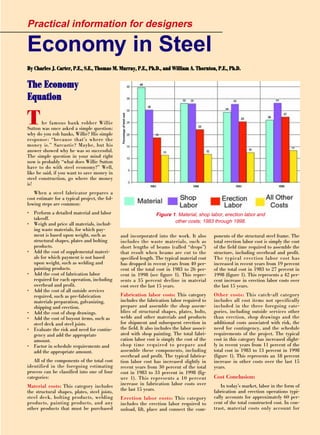
- 1. ponents of the structural steel frame. The total erection labor cost is simply the cost of the field time required to assemble the structure, including overhead and profit. The typical erection labor cost has increased in recent years from 19 percent of the total cost in 1983 to 27 percent in 1998 (figure 1). This represents a 42 per- cent increase in erection labor costs over the last 15 years. Other costs: This catch-all category includes all cost items not specifically included in the three foregoing cate- gories, including outside services other than erection, shop drawings and the additional costs associated with risk, the need for contingency, and the schedule requirements of the project. The typical cost in this category has increased slight- ly in recent years from 11 percent of the total cost in 1983 to 13 percent in 1998 (figure 1). This represents an 18 percent increase in other costs over the last 15 years. Cost Conclusion: In today’s market, labor in the form of fabrication and erection operations typi- cally accounts for approximately 60 per- cent of the total constructed cost. In con- trast, material costs only account for and incorporated into the work. It also includes the waste materials, such as short lengths of beams (called “drops”) that result when beams are cut to the specified length. The typical material cost has dropped in recent years from 40 per- cent of the total cost in 1983 to 26 per- cent in 1998 (see figure 1). This repre- sents a 35 percent decline in material cost over the last 15 years. Fabrication labor costs: This category includes the fabrication labor required to prepare and assemble the shop assem- blies of structural shapes, plates, bolts, welds and other materials and products for shipment and subsequent erection in the field. It also includes the labor associ- ated with shop painting. The total fabri- cation labor cost is simply the cost of the shop time required to prepare and assemble these components, including overhead and profit. The typical fabrica- tion labor cost has increased slightly in recent years from 30 percent of the total cost in 1983 to 33 percent in 1998 (fig- ure 1). This represents a 10 percent increase in fabrication labor costs over the last 15 years. Erection labor costs: This category includes the erection labor required to unload, lift, place and connect the com- TThhee EEccoonnoommyy EEqquuaattiioonn The famous bank robber Willie Sutton was once asked a simple question: why do you rob banks, Willie? His simple response: “because that’s where the money is.” Sarcastic? Maybe, but his answer showed why he was so successful. The simple question in your mind right now is probably “what does Willie Sutton have to do with steel economy?” Well, like he said, if you want to save money in steel construction, go where the money is! When a steel fabricator prepares a cost estimate for a typical project, the fol- lowing steps are common: • Perform a detailed material and labor takeoff. • Weigh and price all materials, includ- ing waste materials, for which pay- ment is based upon weight, such as structural shapes, plates and bolting products. • Add the cost of supplemental materi- als for which payment is not based upon weight, such as welding and painting products. • Add the cost of fabrication labor required for each operation, including overhead and profit. • Add the cost of all outside services required, such as pre-fabrication materials preparation, galvanizing, shipping and erection. • Add the cost of shop drawings. • Add the cost of buyout items, such as steel deck and steel joists. • Evaluate the risk and need for contin- gency and add the appropriate amount. • Factor in schedule requirements and add the appropriate amount. All of the components of the total cost identified in the foregoing estimating process can be classified into one of four categories: Material costs: This category includes the structural shapes, plates, steel joists, steel deck, bolting products, welding products, painting products, and any other products that must be purchased Economy in Steel BByy CChhaarrlleess JJ.. CCaarrtteerr,, PP..EE..,, SS..EE..,, TThhoommaass MM.. MMuurrrraayy,, PP..EE..,, PPhh..DD..,, aanndd WWiilllliiaamm AA.. TThhoorrnnttoonn,, PP..EE..,, PPhh..DD.. Practical information for designers Figure 1. Material, shop labor, erection labor and other costs; 1983 through 1998.
- 2. manner that is consistent, complementary and supplementary to the specification. • Late details can cost a lot. Even simple detail items like roof- or floor-opening frames can cost a small for- tune if delayed, particularly when the delay forces installation after the metal deck is in place. • Show all the structural steel on the structural design drawings. As indicated in the AISC Code of Standard Practice, structural steel items should be shown and sized on the struc- tural design drawings. The architectural, electrical and mechanical drawings can be used as a supplement to the structural design drawings, such as by direct refer- ence to illustrate the detailed configura- tion of the steel framing, but the quanti- ties and sizes should be clearly indicated on the structural design drawings. • Make the GC/CM clearly defines responsibilities for non-structural and miscellaneous steel items. Structural and non-structural steel items are identi- fied in AISC Code of Standard Practice Section 2. Many items, such as loose lin- tels, masonry anchors, elevator framing, and precast panel supports, could be pro- vided by more than one subcontractor. Avoid the inclusion of such items in two bids by clearly defining who is to provide them. • Avoid “catch-all” specification lan- guage. Language like “fabricate and erect all steel shown or implied that is necessary to complete the steel frame- work” probably sounds good to a lawyer, but it really does not add much to quality or economy because it is nebulous and ambiguous. What is implied? Such lan- guage probably results only in arguments, contingency dollars or change orders — and legal fees. • Avoid language that is subject to interpretation. Vague notations, such as “provide lintels as required”, “in a work- manlike manner”, “standard” and “to the satisfaction of the engineer” are subject to widely varying interpretations. Instead, when required, specify measurable per- formance criteria that must be met. • Use standard tolerances. ASTM A6/A6M defines standard mill practice. The AISC Code of Standard Practice defines fabrication and erection tolerances. The Research Council on Structural Connections (RCSC) Specification covers bolting acceptance criteria. The American Welding Society (AWS) D1.1 establishes weld acceptance criteria. These and other documents pro- vide standard tolerances that are accept- approximately 25 percent of the total constructed cost. Clearly then, least weight does not mean least cost. Instead, project economy is maximized when the design is configured to simplify the labor associated with fabrication and erection. Willie Sutton would go after the labor. Ways to Save Time and Money Given The Economy Equation above, the following are some basic suggestions that you can use in your office practice today to work smarter, not harder — and to improve the economy of steel building construction. • Communicate! With the division of responsibilities for design, fabrication and erection that is normal in current U.S. practice, open communication between the engineer, fabricator, erector and other parties in the project is the key to achieving economy. In this way, the expertise of each party in the process can be employed at a time when it is still pos- sible to implement economical ideas. The sharing of ideas and expertise is the key to a successful project. • Take advantage of a pre-bid confer- ence. When in doubt about a framing detail or construction practice, consult a knowledgeable fabricator and/or erector. Most will gladly make themselves avail- able at any stage of the game for a pre- bid conference, such as to help with pre- liminary planning or discuss acceptable and economical fabrication and erection practices. A pre-bid conference can also be used to communicate the require- ments and intent of the project to avoid misunderstandings that can be costly. Many times, fabricators and erectors can provide valid cost-saving suggestions that, if entertained, can reduce cost without sacrificing quality. • Issue complete contract documents, when possible. Design drawings and specifications are the means by which the owner, architect and/or engineer com- municates the requirements for structural steel framing to the fabricator and erec- tor. For guidance on what constitutes complete contract documents, consult the AISC Code of Standard Practice, particu- larly Section 3. When the nature of the project is such that it is not possible to issue complete contract documents at the time of bidding, clearly provide the scope and nature of the work as far as what the framing will be and what kinds of con- nections are required. • Don’t forget to include the basics. Show a North arrow on each plan. Show a column schedule. Include “General Notes” that cover the requirements for painting, connections, fasteners, etc. in a • Watch out for primer/fireproofing and primer/top-coat incompatibility. For steel that is to receive spray-applied fire-protection, the fire protection manu- facturer or applicator should be consult- ed to determine their recommendations and/or preferences for painted or unpainted steel. If a painted surface is preferred, the paint should be compatible with the fire protection. Above all, make sure to coordinate with the architect so the primer and finish coat are compati- ble! • When specifying galvanized mem- bers, keep the maximum lengths in mind. Galvanizing dip tanks are general- ly limited to a member length of 40 ft. Longer members often can be double- dipped, as long as the noticeable zone of overlap between the two dips into the tank is not objectionable. • Clearly state any inspection require- ments in the contract documents. The scope and type of inspection of structural steel should be indicated in the project specification. Make sure that the require- ments for inspection are appropriate for the application. For example, the inspec- tion of groove welds that will always be in compression during their service life is probably not required. Also, make sure shop inspection is scheduled so that it does not disrupt the normal fabrication process. • Avoid the use of brand names when specifying common products. When many manufacturers make a product, or there are acceptably equivalent products, avoid specifying the product by brand name. When it is necessary to indicate a brand name for the purposes of descrip- tion, be sure it is a current, readily avail- able product. Whenever possible, allow the substitution of an “equal”. One excel- lent example: paint. • Try to avoid them entirely, but when you can’t, clearly identify changes and revisions. Changes and revisions that are issued after the date of the contract gen- erally have some cost associated with them. For example, material may have already been ordered, shop drawings may have already been drawn and shipping pieces may have already been fabricated. • Provide meaningful and responsive answers to requests for information. When the fabricator asks for a design clarification through an RFI, the most prompt and complete response, within the limitations of the available informa- tion, will be beneficial to all parties. If the RFI involves information on a shop drawing approval submission, it is best to provide the most specific answer possible.
- 3. able for the majority of cases. Generally, they present the most efficient practices. In some cases, more restrictive tolerances may be contemplated for compatibility with the systems and materials that are supported by the structural steel frame. Or tolerances may need to be defined for highly specialized systems or when steel and concrete systems are mated. All non- standard practices should be cost justi- fied. • Specify paint only when it is needed. Corrosion resistance for architectural or structural purposes may be an important criterion in the performance of structural steel. Often, however, the actual condi- tions of use do not warrant extensive sur- face preparation or shop painting, and in these cases no special surface preparation or treatment should be called for. For example, steel that is enclosed in building finishes, fireproofed, or to be in contact with concrete generally need not be painted. Furthermore, if a finish coat is not specified, a shop primer coat need not be specified as it is of only minor influence on corrosion in the construc- tion phase. For more information, see AISC Specification Section M3 and its Commentary. • When painting is necessary, don’t ask too much of the shop coat. The shop coat of paint (primer) is temporary and will provide minimal protection dur- ing exposure for steel that is to receive a finish coat in the field. • Also, when painting is necessary, select the right surface preparation and paint system for the job. The three most commonly used surface prepara- tions are SSPC SP-2 (hand-tool clean- ing), SSPC SP-3 (power-tool cleaning) and SSPC SP-6 (commercial blast clean- ing). SSPC SP-2 or SP-3 cleaning is usu- ally satisfactory for an ordinary shop prime coat. If conditions call for a high- performance paint system for long term, low maintenance protection, SSPC SP-6 is more frequently required. When assemblies are to be blast cleaned, con- sider the limitations on size and length, which vary depending upon the available equipment. • Careful consideration should also be given to specifying a paint system that will satisfy the required degree of cor- rosion protection. A high-quality paint system (or galvanizing) can be cost-effec- tive or even essential for certain applica- tions, as in open parking structures. In these cases, life-cycle costing should be performed. An alternative to high-quality surface treatments, in normal atmospher- ic environments, may be ASTM A588 (weathering) steel. Try to avoid responses such as “architect to supply”, “general contractor to sup- ply”, or “verify in field”. • Use 50 ksi steel in wide-flange mem- ber design. U.S. wide-flange steel shape production today is normally 50 ksi by default. Specifying ASTM A992, ASTM A572 grade 50 or ASTM A529 grade 50 is the same cost as or within pennies per pound of specifying ASTM A36 material. • Use 36 ksi steel for plates and angles. ASTM A36 material is still predominant in angles; so much so that it is difficult to obtain 50 ksi angle material, except by special order from the rolling mill. Additionally, there is still a cost differen- tial between 36 ksi and 50 ksi plate prod- ucts. • Consider the use of hollow structural sections (HSS). Square and rectangular HSS are available in ASTM A500 grades B and C with 46 and 50 ksi yield strengths, respectively. Round HSS are available in ASTM A500 grades B and C with 42 and 46 ksi yield strengths, respectively. Although their material cost is generally higher, HSS generally have less surface area to paint or fireproof (if required), excellent weak-axis flexural and compressive strength, and excellent torsional resistance when compared with wide-flange cross-sections. • Be careful when specifying beam camber. Don’t specify camber below ¾- in.; small camber ordinates are impracti- cal and a little added steel weight may be more economical anyway. Also, do not overspecify camber. Deflection calcula- tions are approximate and the actual end restraint provided by simple shear con- nections tends to lessen the camber requirement. Consider specifying from two-thirds to three-quarters of the calcu- lated camber requirement for beams spanning from 20’ to 40’, respectively, to account for connection and system restraint. In any case, watch out when rounding up the calculated camber ordi- nate, particularly with composite designs. Shear studs are unforgiving in that they can protrude through the top of the slab when too little camber is relieved under the actual load. Alternatively, allow suffi- cient slab thickness to account for reduced actual deflection. Also, the min- imum length of a beam that is to be cam- bered is about 25’. Why? Because the fabrication jig that is used to camber beams is usually configured with pivot restraints that hold the beam from 18’ to 20’ apart. To make sure there is adequate beam extending beyond this point to resist the concentrated force from the cambering operation, a 25’ beam is gen- erally required. • Economize web penetrations to min- imize or eliminate stiffening. Web pen- etrations in beams are often a cost-effec- tive means of minimizing the depth of a floor system that contains mechanical or electrical ductwork. However, if they are numerous and require stiffening, it is probably more economical to eliminate them and pass all ductwork below the beams, if possible. Thus, stiffening at web penetrations should be called for only if required. The use of a heavier beam, a relocated opening, a change in the size of the opening, and the use of current design procedures can often eliminate the need for reinforcement of beam web penetrations. If web penetrations are to be use and stiffening is required, the most efficient and economical detail is the use of longitudinal stiffeners above and below the opening as illustrated in Figure 2. For more information on designing web openings, see AISC Design Guide #2: Steel and Composite Beams with Web Openings (call 800/644-2400 or visit www.aisc.org). • Favor the use of partially composite action in beam design. Although shear stud installation costs vary widely by region, on average, one installed shear stud equates to 10 lb of steel. Fully com- posite designs are not usually the most economical because the average weight savings per stud is less than 10 lb. Modern Steel Construction / April 2000 Figure 2. Web penetration reinforcement of an I-shaped beam.
- 4. Sometimes, the average weight savings per stud for 50 to 75 percent composite beams can exceed the point of equivalen- cy. In some cases, non-composite con- struction can be most economical. A caveat: make sure that the beam in a composite design is adequate to carry the weight of the wet concrete. • When composite construction is specified, the size, spacing, quantity and pattern of placement of shear stud connectors should be specified. It should also be compatible with the type and orientation of the steel deck used. When evaluating the relative economy of composite construction, keep in mind that most shear stud connector installers charge a minimum daily fee. So, unless there are enough shear stud connectors on a job to warrant at least a day’s work, it may be more economical to specify a heavier non-composite beam. • Shear stud connectors should be field installed, not shop installed. Otherwise, they are a tripping hazard for the erector’s personnel on the walking surface of steel beams. • Consider cantilevered construction for roofs and one-story structures. Cantilevered construction was invented primarily to reduce the weight of steel required to frame a roof. Although today we are less concerned with weight sav- ings than labor savings, cantilevered con- struction may still be a good option. Why? Because the associated connections of the members are generally simple to fabricate and fast and safe to erect. • Use rolled-beam framing in areas that will support mechanical equip- ment. It always happens. The structural design is performed based upon a prelim- inary estimate of the loads from the mechanical systems and units. Later, the mechanical equipment is changed and the loads go up — way up — sometimes after construction has begun. Rolled- beam framing offers much greater flexi- bility than other alternatives, such as steel-joist framing, to accommodate these changing design loads. • Optimize bay sizes. It is still a good idea to design initially for strength and deflection. Subsequently, geometry and compatibility can be evaluated at connec- tions, with shape selections modified as necessary. John Ruddy, Structural Affiliates International, suggests that using a bay length of 1.25 to 1.5 times the width, a bay area of about 1000 sq. ft., and filler beams spanning the long direction combine to maintain economi- cal framing. But…avoid shallow beam depths that require reinforcement or added detail material at end connections. Detail mate- rial such as reinforcement plates at copes and haunching to accommodate deeper, special connections is typically far more expensive than simply selecting a deeper member that can be connected more cleanly. If the beam is changed from a W16x50 to a W18x50, the simplified connection is attained virtually for free. And …don’t change member size fre- quently just because a smaller or lighter shape can be used. Try to get the usage of any given member size to a mill order quantity (approximately 20 tons). Of course smaller quantities can be used and are commonly purchased by the fabrica- tor from service centers (at a cost premi- um), but detailing, inventory control, fab- rication and erection are all simplified with repetition and uniformity. Keep in mind that economy is generally synony- mous with the fewest number of different pieces. Above all …select members with favor- able geometries. Watch out for connec- tions at changes in floor elevations; a deeper girder may simplify the connec- tion detail. Also, watch out for W10, W8 and W6 columns, which can have narrow flanges and web depth; connecting to either axis is constrained and difficult. It is often most helpful to make rough sketches of members to approximate scale in their relative positions to discov- er geometric incompatibilities. • Use repetitive plate thicknesses throughout the various detail materi- als in a project. Just like with member sizing, the use of similar plate thickness throughout the job is generally more eco- nomical than changing thicknesses just because you can. For example, use one or two plate thicknesses for all the col- umn base plates. This same idea applies for other detail materials, such as trans- verse stiffeners and web doubler plates. • Design floor framing to minimize the perceptibility of vibrations. Floor vibration can be an unintended result in service when floors are designed only for strength and deflection limit-states and an absolute-minimum-weight system is chosen. Today’s lighter construction, when combined with the lack of damping due to partitionless open office plans and light actual floor loadings (in the era of the nearly paperless office), has exacer- bated the potential for floor vibration problems. For information on designing to minimize floor vibration, see AISC Design Guide#11: Floor Vibrations Due To Human Activity (call 800/644-2400 or visit www.aisc.org). • When designing for snow-drift load- ing, decrease beam spacing as the framing approaches the bottom of a parapet wall. Reduced beam spacing allows the same deck size to be used and the same beam size to be repeated into a parapet against which snow may drift. This is generally more economical than maintaining the same spacing and chang- ing the deck and beam sizes. • Minimize the need for stiffening. When required at locations of concen- trated flange forces, transverse stiffeners and web doubler plates are labor inten- sive detail materials. For the sake of economy, using 50 ksi steel and/or a member with a thicker flange or web can often eliminate them. In the latter case, consider trading some less expensive member weight for reduced labor requirements. Always remember to reduce the panel-zone web shear force by the magnitude of the story shear. This can often mean the difference between having to use a web doubler plate and not. See AISC Design Guide No. 13 Wide- Flange Column Stiffening at Moment Connections. (call 800/644-2400 or visit www.aisc.org). • Eliminate column splices, if feasible. On average, the labor involved in making a column splice equates to about 500 lb of steel. Consider the elimination of a column splice if the resulting longer col- umn shaft remains shippable and erectable. If a column is spliced, locating the splice at 4 to 5 ft above the floor will permit the attachment of safety cables directly to the column shaft, where need- ed. It will also allow the assembly of the column splice without the need for scaf- folding or other accessibility equipment. If the column splice design requires welding in order to attain continuity, consider the use of PJP groove welds rather than CJP groove welds for econo- my. • Configure column base details that are erectable without the need for guying. Use a four-rod pattern, base- plate thickness, and attachment between column and base that can withstand gravity and wind loads during erection. At the same time, make sure the footing detail is also adequate against overturn- ing due to loads during erection. For more information, refer to AISC Design Guide #10: Erection Bracing of Low-Rise Structural Steel Frames (call 800/644- 2400 or visit www.aisc.org). • Make your column base details repetitive, too. The possibility of foun- dation errors will be reduced when repet- itive anchor-rod and base-plate details are used. Keep your anchor-rod spacings
- 5. uniform throughout the job. Use headed rods or rods that have been threaded with a nut at the bottom if there is any calculated uplift. Otherwise, hooked rods can also be used if desired. Be sure to identify both the length of the shaft and the hook if so. • Allow the use of the right column- base leveling method for the job. Three methods are commonly used to level column bases: leveling plates, level- ing nuts and washers and shim stacks and wedges. Regional practices and prefer- ences vary. However, the following com- ments can be stated in general. Leveling plates lend themselves well to small- to medium-sized column bases, say up to 24”. Shim stacks and wedges, if used properly, can be used on a wide variety of base sizes. Proper use means maintain- ing a small aspect ratio on the shim stack, possibly tack welding the various plies of the shim stacks to prevent relative move- ment and secure placement of the devices to prevent inadvertent displace- ment during erection operations and when load is applied. Leveling nuts and washers lend themselves well to medium- sized base plates, say 24” to 36”, but are only practical when the four-rod pattern of anchor rods is spaced to develop satis- factory moment resistance. Large column base plates, say over 36”, can become so heavy that they must be shipped inde- pendently of the columns and preset, in which case grout holes and special level- ing devices are usually required. • Don’t over-specify the details of sec- ondary members. For example, span- drel kickers and diagonal braces can often be provided as square or bevel-cut elements that get welded into the braced member and structural element that pro- vides the bracing resistance with a very simple line of fillet weld. In contrast, it is very costly to require that such secondary details be miter-cut to fit the profile of a member or element to which it is con- nected and welded all-around. • Keep relieving angles in a practical size range. The thickness of relieving angles is normally 5/16” or 3/8”. If a greater thickness is required for strength, the basic design assumptions should be reviewed and perhaps modified. If verti- cal and/or horizontal adjustment of masonry relieving angles is required, the amount of adjustment desired should be specified and the fabricator should be allowed to select the method to achieve this adjustment, such as by slotting or shimming. Final adjustments to locate relieving angles should be made by the mason, preferably after dead load deflec- tion of the spandrel member occurs. • Consider if heavy hot-rolled shapes are really necessary in lighter and miscellaneous applications. Ordinary roof openings can usually be framed with angles rather than W-shapes or channels. As another example, heavy rolled angles for the concrete floor slab stop (screed angles) are unnecessary if a lighter gage- metal angle will suffice (something in the 10 to 18 gage range, depending upon slab thickness and overhang). These lighter angles can often be supplied with the metal deck and installed with puddle welding, simplifying the fabrication of the structural steel. Small roof openings on the order of 12 in. square or less proba- bly need not be framed at all unless there is a heavy suspended load, such as a leader pipe. • Limit the use of different bolt grades and diameters. It is seldom feasible to use more than one or two combinations of bolt diameters and grades on a project. The use of different diameters for differ- ent grades simplifies the quality assur- ance task of ensuring that each strength grade was used in the proper location. It also allows more shop efficiency in the drilling or punching operations. • Use ASTM A325 bolts whenever pos- sible. They are strong, ductile, and reli- able — the best fastener value. • Limit bolt diameter to 1”. Diameters of ¾” and 7/8” are preferred and 1” diameter is still within the installation capability of most equipment. Larger diameters require special equipment and increased spacings and edge distances than are typical. • Select the right bolt hole type for the application. In steel-to-steel structural connections, standard holes can be used in many bolted joints and are preferred in some cases. For example, standard holes are commonly used in girder and spandrel connections to columns to more accurately control the dimension between column centers and facilitate the plumbing process. In large joints, particu- larly those in the field, the use of over- sized holes or slotted holes can reduce fit-up and assembly time and the associ- ated costs. For further information, see the RCSC Specification. • Open holes need not be filled for structural purposes. Sometimes, bolt holes remain in the structure without bolts in them. Whether this is because a temporary bolted connection was made at that location, a design modification was made during construction or for other reasons, there is no structural con- sequence of not having a bolt installed in the hole. • Don’t confuse the requirements for bolts and bolt holes in steel-to-steel structural connection with those for anchor rods and anchor-rod holes. There are many differences between steel-to-steel structural connections and steel-to-concrete anchorage applications, including the following important ones: • While ASTM A325 and A490 bolts are most commonly used in steel-to-steel structural connections, they are not appropriate for use in steel-to-con- crete anchorage applications. For anchor rods, ASTM F1554 is a new umbrella specification for headed, threaded/nutted and hooked anchor rods (they still call them anchor bolts) in three material strengths: 36 ksi, 55 ksi and 105 ksi. Of course, you can also use ASTM A36, A572, A449 (strength equivalent of A325 in rod), A354 (strength equivalent of A490 in rod). • The hole sizes that are permitted in base plates and similar devices for anchor rods are larger for any given diameter to account for the larger placement tolerances on anchor rods. • Installation is totally different. That is, pretension is sometimes specified for steel-to-steel structural connections, but not normally for steel-to-concrete anchorage applications. • Washer requirements are also differ- ent. Anchor rods generally require thicker, larger washers that are often made out of plate stock. • Use snug-tightened installation whenever possible. Snug-tightened installation requirements (the full effort of an ironworker with an ordinary spud wrench that brings the connected plies, but without any specific level of clamping force between them) recognize that most bolts in shear need not be pretensioned; for further information, see the RCSC Specification. The maximum shear strength per bolt is realized while the related installation and inspection costs are minimized. As given in the AISC Specification, the cases that must be pre- tensioned include: tall building column splices, connections that brace tall build- ing columns, some connections in crane buildings, bolts subject to direct tension (AISC and RCSC are currently consider- ing a relaxation of this requirement for ASTM A325 bolts in non-fatigue and non-impact applications), connections subject to impact or significant load reversal, and slip-critical connections. • Permit the use of any of the four approved methods for pretensioning high-strength bolts, when pretension- ing is necessary. RCSC provides four Modern Steel Construction / April 2000
- 6. approved installation methods for high- strength bolts that must be pretensioned: the turn-of-nut method, the calibrated wrench method, the twist-off-type ten- sion-control bolt method and the direct- tension-indicator method. Different fabri- cators and erectors have different preferences, which mostly center on the installation cost that is associated with their use of each of these methods. When properly used in accordance with RCSC requirements, these methods all provide acceptable results. Therefore, it is in the interest of economy to allow the installer the flexibility to choose their preferred method and properly use it. For more information, see the RCSC Specification. • Minimize the use of slip-critical con- nections. Most connections with three or more bolts have normal misalignments that would cause some of the bolts to be in bearing initially. Furthermore, the nor- mal methods of erection usually cause bolts to slip into bearing during erection. Additional slip beyond this point is usual- ly negligible. Special faying surface requirements add cost due to required masking or use of a special paint system. Furthermore, additional installation and inspection requirements add cost. Therefore, generally limit usage of slip- critical connections to those cases required by AISC/RCSC, including: con- nections with oversized holes or slotted holes not perpendicular to load; end con- nections of built-up members, and con- nections that share load between bolts and welds. For more information, see the AISC Specification and the RCSC Specification. • Follow RCSC Specification require- ments for the use of washers. The use of hardened washers is often unneces- sary; see the RCSC Specification for when they are necessary. However, some fabri- cators and erectors elect to use a hard- ened washer under the turned element to prevent galling of the connected material, which would otherwise increase wear and tear on the installation equipment. Lock washers are not intended for use with ASTM A325 or A490 bolts, nor should they be specified or used. • Design connections for actual forces. Or at least do not overspecify the design criteria. In U.S. practice, the Engineer of Record sometimes specifies standard reactions for use by the connection designer. These standard reactions can sometimes be quite conservative; look at the extreme example illustrated in Figure 3. However, design for the actual forces generally allows more widespread use of typical connections, which improves economy. Axial forces, shears, moments and other forces should be shown as the most economical welded joint will generally result when weld metal volume is minimized. Furthermore, reducing the weld metal volume reduces the heat input and the resulting shrinkage and distortion. Minimizing the weld metal also minimizes the potential for weld defects. • Favor fillet welds over groove welds. Fillet welds generally require less weld metal than groove welds. Additionally, the use of fillet welds virtually eliminates base metal preparation, which is labor intensive. • Configure fillet weld length to reduce weld size. Compare a ¼” fillet weld 12” long with a ½” fillet weld 6”- long. These welds have equal strength, but the latter weld requires twice as much weld metal volume and cost. With due consideration of the implications of increased weld length on the size of con- necting elements, such as gusset plates, the best balance can be found. • Keep fillet weld sizes at or below 5/16” when possible. Per AWS D1.1, this weld size can be deposited in one pass with the shielded metal arc welding (SMAW) process in the horizontal and flat positions. Larger weld sizes will require multiple passes. • Don’t always weld on both sides of a piece just because you can. There are many applications where it may be possible to weld on one side of a joint only. For example, the attachment of a column base plate to a column can in many cases be made with fillet welds on one side of each flange and the web. This same idea is also sometimes possible with transverse stiffeners, bearing stiffeners and other similar elements. • Use intermittent fillet welds when possible. Under typical loading, intermit- tent fillet welds can often be specified and the weld metal volume can be reduced accordingly. However, not in applications that involve fatigue. applicable so that proper connections can be made and costly overdesign, as well as dangerous underdesign, can be avoided. This applies to shear connections, moment connections, bracing connec- tions, column splices — all connections! The actual reactions are quite important for the proper design of end connections for beams in composite construction. • Are your bolt threads automatically excluded from the shear planes of the joint? For ASTM A325 and A490 bolts, a 3/8”-thick ply adjacent to the nut will exclude the threads in all cases when the bolt diameter is 3/4” or 7/8”. A 1/2”- thick ply adjacent to the nut will exclude the threads in all cases when the bolt diameter is 1” or 1-1/8”. Use a washer under the nut and you can reduce these minimum ply thicknesses by 1/8”. Depending upon the combination of grip, number and placement of washers and selected bolt length a lesser ply thickness may also work with the threads-excluded condition. • Take the easy way out on prying action in bolted joints. Prying action, the additional tension that results in a bolted joint due to deformation of the connected parts, generally requires detailed calculations to determine the combination of bolt diameter, gage and fitting thickness that is required to trans- mit the design forces. Simplify the whole process as follows. As a first step, calcu- late the fitting thickness that is required to reduce the prying action to an insignif- icant (i.e., negligible) amount. If this thickness is present or can be provided, there is no further need for prying action calculations. If this thickness is excessive or cannot be provided, then use the more detailed calculation approach that match- es the proper arrangement of bolt diame- ter, gage and fitting thickness to transmit the loads with prying action. • Configure welded joints to minimize the weld metal volume. Each pound of weld metal has a deposition time (and labor cost) associated with it. Therefore, Figure 3. Extreme example of what arbitrary connection criteria can mean.
- 7. • Favor the horizontal and flat posi- tions. These positions use the base metal and gravity to hold the molten weld pool in place, allowing easier welding with a faster deposition rate and generally high- er weld quality. • Recognize the increased strength in transversely loaded fillet welds. It has long been known that a fillet weld loaded transversely is up to 50 percent stronger than the same weld loaded longitudinally. AISC Specification Appendix J2.4 pro- vides a means to take advantage of this strength increase. As a result, values in the eccentrically loaded weld group tables in the current AISC Manual are typically from ten to 30 percent higher than in the previous edition. This is par- ticularly useful for transverse stiffener end welds, which are purely transversely loaded and qualify for a full 50 percent increase in shear strength. • Avoid the use of the weld-all-around symbol. This welding is excessive in most cases. It may even be wrong in some. Welding all around may violate the AISC Specification requirement that welds on opposite sides of a common plane be interrupted at the corner (i.e., when the weld would have to wrap around the cor- ner at an overlap). Also, the weld-all- around symbol should not be used if the entire perimeter of the weld cannot be reached. • Consider the AWS acceptance crite- ria when an undersized weld is discov- ered. AWS D1.1 allows a 1/16” undersize to remain if it occupies less than ten per- cent of the weld length. This recognizes that an attempted repair may create a worse condition than the undersized weld. • Avoid seal welding unless it is required. Seal welding is generally unnecessary, unless the joint is required to be air-tight or water-tight. • For groove welds, favor partial-joint- penetration (PJP) over complete-joint- penetration (CJP). PJP groove welds generally require less base metal prepara- tion and weld metal. They also reduce heat input, shrinkage, and distortion. It is sometimes possible to increase plate thickness and use a PJP groove weld instead of a CJP groove weld. • Select a groove-welded joint with a preparation that minimizes weld metal volume. Depending upon thickness, a particular combination of root opening and bevel angle will minimize weld metal volume. The combination that requires the least amount of weld metal should be selected. Also, consider double-sided preparation. In some cases, the additional labor to prepare the surface can be offset by savings in weld metal volume (and labor). • Watch out for weld details that will likely cause distortion as the welds cool and shrink. Welding (and in many cases, flame cutting) causes distortion because the heated regions are restrained by the rest of the steel as they cool and contract. Under extreme circumstances, a structural member could be distorted so severely that straightening of the member would be required, particularly in an application that involves architecturally exposed structural steel, with the resul- tant increase in cost. The potential for distortion can frequently be reduced through proper selection of the connec- tion configuration and joint details. The fabricator is the best source of guidance and advice for avoiding potentially trou- blesome details. • Know what to look for when moni- toring interpass temperatures in weld- ed joints. For a given level of heat input, the interpass temperature in a weldment is largely dependent upon the cross-sec- tional area of the element(s) being weld- ed. The larger the area, the faster the heat will be drawn from the weldment. As a rule of thumb, if the cross-sectional area of the weld is equal to or greater than 40 in.2 , the minimum interpass tem- perature should be monitored. Conversely, if the cross-sectional area of the weld is equal to or less than 20 in.2 , the maximum interpass temperature should be monitored. • Avoid welding on galvanized sur- faces. When at all possible, avoid design situations that will require welding on galvanized surfaces, particularly in the shop. Special ventilation must be provid- ed in the shop to exhaust the toxic fumes that are produced. Additionally, the gal- vanizing must commonly be removed by grinding in the area to be welded. This requires the subsequent touching up with cold galvanizing compound after welding and cleaning. All of these operations add cost. • Consider the fabricator’s and erec- tor’s suggestions regarding connec- tions. To a large extent, the economy of a structural steel frame depends upon the difficulty involved in the fabrication and erection, which is a direct function of the connections. The fabricator and erector are normally in the best position to iden- tify and evaluate all the criteria that must be considered when selecting and detail- ing the optimum connection, including such non-structural considerations as equipment limitations, personnel capabil- ities, season of erection, weight, length limitations and width limitations. The fabricator will also know when variations in bolt diameters and holes sizes, broken gages, combination of bolting and weld- ing on the same shipping piece will incur excessive and costly material handling requirements in the shop. • Use one-sided shear connections, when possible. One-sided connections such as single-plates and single-angles have well-defined performance, are eco- nomical to fabricate and are safe to erect in virtually all configurations. When com- bined with reasonable end-reaction requirements, one-sided connections can be used quite extensively to simplify con- struction. Sometimes, however, end reac- tions are large enough to preclude their use because of the strength limitations of such connections. • Avoid through-plates on HSS columns; use single-plate shear con- nections whenever possible. A single- plate connection can be welded directly to the column face in all cases where punching shear does not control and the HSS is not a slender-element cross-sec- tion. For more information, refer to the AISC HSS Connections Manual. • Consider partially restrained (PR) moment connections. PR moment con- nections can provide adequate strength and stiffness for many buildings, particu- larly those with long frame lines where many connections of reduced stiffness can be mobilized. PR connections can be configured to minimize field welding, simplify the connection details, and speed erection. • Design columns to eliminate web doubler plates (especially) and trans- verse stiffeners (when possible) at moment connections. The elimination of labor-intensive items such as web dou- bler plates and stiffeners is a boon to economy. One fillet-welded doubler plate can generally be equated to about 300 lb of steel; one pair of fillet welded stiffeners can generally be equated to about 200 lb of steel. Additionally, their elimination simplifies weak-axis framing. See AISC Design Guide No. 13 Wide-Flange Column Stiffening at Moment Connections (call 800/644-2400 or visit www.aisc.org). Charles J. Carter, S.E., P.E., is AISC’s Director of Engineering and Continuing Education. Thomas M. Murray, P.E., Ph.D. is Montague-Betts Professor of Civil Engineering at Virginia Polytechnic and State University, and a previous recipient of the AISC T.R. Higgins Award. William A. Thornton, P.E., Ph.D is Chief Engineer at Cives Steel Companyy, and a previous recipient of the AISC T.R. Higgins Award..