
Recommended
More Related Content
What's hot
What's hot (20)
Viewers also liked
Viewers also liked (15)
Similar to Bolt Length Calculator with Single Nut & Washer
Similar to Bolt Length Calculator with Single Nut & Washer (20)
Recently uploaded
Recently uploaded (20)
Bolt Length Calculator with Single Nut & Washer
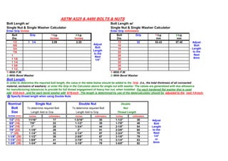
- 1. Bolt Length w/ Bolt Length w/ Single Nut & Single Washer Calculator Single Nut & Single Washer Calculator Enter Grip Inches Enter Grip millimeters Bolt Grip 1-Lg. 2-Lg. Bolt Grip 1-Lg. 2-Lg. Dia. Inches Inches Dia. mm mm 1/2 1 1/4 2.09 2.25 13 32 53.43 57.40 5/8 16 3/4 19 7/8 22 1 25 1 1/8 30 1 1/4 32 1 3/8 35 1 1/2 38 1 -With F.W. 1 -With F.W. 2 -With Bevel Washer 2 -With Bevel Washer Bolt Length In order to determine the required bolt length, the value in the table below should be added to the Grip (I.e., the total thickness of all connected material, exclusive of washers) or enter the Grip in the Calculator above for single nut with washer. The values are generalized with due allowance for manufacturing tolerances to provide for full thread engagement of heavy hex nut, when installed. For each hardened flat washer that is used add 5/32-inch , and for each bevel washer add 5/16-inch . The length is determined by use of the table/calculator should be adjusted to the next 1/4-inch. Specify thread length when using Double Nuts Nominal Single Nut Double Nut Double Bolt To determine required Bolt To determine required Bolt Nut Size Length Add to Grip Length Add to Grip Thread Length Inches (mm) Inches millimeters Inches millimeters Inches millimeters 1/2" (13) 11/16" 17 1-3/16" 30 1-1/2" 38 5/8" (16) 7/8" 22 1-1/2" 38 1-7/8" 48 3/4" (19) 1" 25 1-3/4" 44 2-1/8" 54 7/8" (22) 1-1/8" 29 2" 51 2-3/8" 60 1" (25) 1-1/4" 32 2-1/4" 57 2-3/4" 70 1-1/8" (29) 1-1/2" 38 2-5/8" 67 3-1/8" 79 1-1/4" (32) 1-5/8" 41 2-7/8" 73 3-1/4" 83 1-3/8" (35) 1-3/4" 44 3-1/8" 79 3-5/8" 92 ASTM A325 & A490 BOLTS & NUTS Adjust Bolt Length to the Next 1/4" Adjust Bolt Length to the Next 6mm Adjust Bolt Length to the Next 1/4" or 6mm
- 2. 1-1/2" (38) 1-7/8" 48 3-3/8" 86 3-3/4" 95 Bolted Parts (ASTM A325 & A490 BOLTS) The slope of surfaces of bolted parts in contact with the bolt head and nut shall not exceed 1:20 with respect to plane normal to the bolt axis. Bolted steel parts shall not be separated by gaskets and shall fit solidly together after bolts are tightened. Holes may be be punched, sub-punched and reamed, or drilled, as required by applicable code or specification. Standard holes shall have a diameter 1/16" in excess of the nominal bolt diameter. A490 bolts and galvanized A325 bolts shall not be reused. Retightening previous tightening of adjacent bolts shall not be considered as reuse. Oversized Holes may have nominal diameters up to: 3/16" larger than bolts 7/8" and less in diameter, 1/4" for 1" in diameter and 5/16" larger than bolts 1-1/8" and greater in diameter. Haredened washers shall be installed over oversized holes in an outer ply. Max. Holes Size (Nominal) Inches Max. Holes Size (Nominal) millimeters Nominal Oversize Short Long Nominal Oversize Short Long Bolt Holes Slotted Slotted Bolt Holes Slotted Slotted Size Holes Holes Size Holes Holes 1/2" 5/8" 9/16"x11/16" 9/16"x1-1/4" 13 16 14x17 14x32 5/8" 13/16" 11/16"x7/8" 11/16"x1-9/16" 16 21 17x22 17x40 3/4" 15/16" 13/16"x1" 13/16"x1-7/8" 19 24 21x25 21x48 7/8" 1-1/16" 15/16"x1-1/8" 15/16"x2-3/16" 22 27 24x29 24x56 1" 1-1/4" 1-1/16"x1-5/16" 1-1/16"x2-1/2" 25 32 27x33 27x64 1-1/8" 1-7/16" 1-3/16"x1-1/2" 1-3/16"x2-13/16" 29 37 30x38 30x71 1-1/4" 1-9/16" 1-5/16"x1-5/8" 1-5/16"x3-1/8" 32 40 33x41 33x79 1-3/8" 1-11/16" 1-7/16"x1-3/4" 1-7/16"x3-7/16" 35 43 37x44 37x87 1-1/2" 1-13/16" 1-9/16"x1-7/8" 1-9/16"x3-3/4" 38 46 40x58 40x95 >1-1/2" d+5/16" (d+1/16")x(d+3/8") (d+1/16")x(2.5xd) >38 >46 (d+2)x(d+9) (d+2)x(2.5xd) Minimum Bolt Spacing The distance between centers of standard, oversized, or slotted fasteners shall be not less than 2 2/3d where "d" is the nominal diameter of the fastener, inches. A distance of 3d is preferred. Minimum Edge Distance Table Inches Minimum Edge Distance Table millimeters (Center of Standard Hole to Edge of Connected Part) (Center of Standard Hole to Edge of Connected Part) Oversized and Slotted Holes 6mm
- 3. Nominal @ '@' Rolled Edges of Nominal @ '@' Rolled Edges of Bolt Sheared Plates, Shapes or Bars Bolt Sheared Plates, Shapes or Bars Size Edges or Gas Cut Edges Size Edges or Gas Cut Edges 1/2" 7/8" 3/4" 13 22 19 5/8" 1-1/8" 7/8" 16 29 22 3/4" 1-1/4" 1" 19 32 25 7/8" 1-1/2" * 1-1/8" 22 38 29 1" 1-3/4" * 1-1/4" 25 44 32 1-1/8" 2" 1-1/2" 29 51 38 1-1/4" 2-1/4" 1-5/8" 32 57 41 >1-1/4" 1.75x Dia. 1.25x Dia. >32 1.75x Dia. 1.25x Dia. These may be 1-1/4" @ the ends of beam connection angles These may be 32 @ the ends of beam connection angles Bolt Size Inches (mm) Inches (mm) Inches (mm) A B C A B C 1/4" (6) 3/4" (19) 1/2" (13) 1/2" (13) 1" (25) 7/8" (22) 5/8" (16) 3/8" (10) 1-1/8" (29) 3/4" (19) 3/4" (19) 1-3/8" (35) 1-1/8" (29) 3/4" (19) c BA Socket Wrench Open End Wrench Wrench Clearance Guide
- 4. 1/2" (13) 1-3/8" (35) 7/8" (22) 7/8" (22) 1-3/4" (44) 1-3/8" (35) 7/8" (22) 5/8" (16) 1-5/8" (41) 1" (25) 1" (25) 2-1/8" (54) 1-1/2" (38) 1-1/8" (29) 3/4" (19) 1-7/8" (48) 1-1/8" (29) 1-1/8" (29) 2-5/8" (67) 1-5/8" (41) 1-1/4" (32) 7/8" (22) 2-1/8" (54) 1-1/4" (32) 1-1/4" (32) 3" (76) 1-7/8" (48) 1-5/8" (41) 1" (25) 2-3/8" (60) 1-3/8" (35) 1-3/8" (35) 3-1/4" (83) 2-1/8" (54) 1-7/8" (48) 1-1/8" (29) 2-5/8" (67) 1-1/2" (38) 1-1/2" (38) 3-3/8" (86) 2-1/4" (57) 1-7/8" (48) 1-1/4" (32) 2-7/8" (73) 1-5/8" (41) 1-5/8" (41) 3-7/8" (98) 2-1/2" (64) 2" (51) 1-3/8" (35) 3-1/8" (79) 1-3/4" (44) 1-3/4" (44) 4-3/8" (111) 2-3/4" (70) 2-1/4" (57) 1-1/2" (38) 3-3/8" (86) 1-7/8" (48) 1-7/8" (48) 4-7/8" (124) 2-7/8" (73) 2-1/2" (64) Bolt Dimensions. Inches Nut Dimensions, Inches Nominal Heavy Hex Structural Bolts Heavy Hex Nuts Bolt Size Width across Height Thread Width across Height D flats F H Length flats W H 1/2" (13) 7/8" (22) 5/16" (8) 1" (25) 7/8" (22) 31/64" (12) 5/8" (16) 1-1/16" (27) 25/64" (10) 1-1/4" (32) 1-1/16" (27) 39/64" (15) 3/4" (19) 1-1/4" (32) 15/32" (12) 1-3/8" (35) 1-1/4" (32) 47/64" (19) 7/8" (22) 1-7/16" (37) 35/64" (14) 1-1/2" (38) 1-7/16" (37) 55/64" (22) 1" (25) 1-5/8" (41) 39/64" (15) 1-3/4" (44) 1-5/8" (41) 63/64" (25) 1-1/8" (29) 1-13/16" (46) 11/16" (17) 2" (51) 1-13/16" (46) 1-7/64" (37) 1-1/4" (32) 2" (51) 25/32" (20) 2" (51) 2" (51) 1-7/32" (31) 1-3/8" (35) 2-3/16" (56) 27/32" (21) 2-1/4" (57) 2-3/16" (56) 1-11/32" (34) 1-1/2" (38) 2-3/8" (60) 15/16" (24) 2-1/4" (57) 2-3/8" (60) 1-15/32" (37) Circular Washers Sq. or Rect. Bevel Washers Nominal Nominal Nominal Thickness Minimum Slope or ASTM A325 & A490 BOLTS & NUTS DIMENSIONS,Inches (mm) WASHER DIMENSIONS, Inches (mm) F Bolt Length H W H
- 5. Bolt Size Outside Diameter Side Mean Taper in D Diameter of Hole Min. Max. Dimension Thickness Thickness 1/2" (13) 1-1/16" (27) 17/32" (13) 0.097 (2) 0.177 (4) 1-3/4" (44) 5/16" (8) 1:6' 5/8" (16) 1-5/16" (33) 11/16" (17) 0.122 (3) 0.177 (4) 1-3/4" (44) 5/16" (8) 1:6' 3/4" (19) 1-15/32" (37) 13/16" (21) 0.122 (3) 0.177 (4) 1-3/4" (44) 5/16" (8) 1:6' 7/8" (22) 1-3/4" (44) 15/16" (24) 0.136 (3) 0.177 (4) 1-3/4" (44) 5/16" (8) 1:6' 1" (25) 2" (51) 1-1/8" (29) 0.136 (3) 0.177 (4) 1-3/4" (44) 5/16" (8) 1:6' 1-1/8" (29) 2-1/4" (57) 1-1/4" (32) 0.136 (3) 0.177 (4) 2-1/4" (57) 5/16" (8) 1:6' 1-1/4" (32) 2-1/2" (64) 1-3/8" (35) 0.136 (3) 0.177 (4) 2-1/4" (57) 5/16" (8) 1:6' 1-3/8" (35) 2-3/4" (70) 1-1/2" (38) 0.136 (3) 0.177 (4) 2-1/4" (57) 5/16" (8) 1:6' 1-1/2" (38) 3" (76) 1-5/8" (41) 0.136 (3) 0.177 (4) 2-1/4" (57) 5/16" (8) 1:6' Length Weight of ASTM A325 or A490 high strength bolts Under Head Heavy Hex Structural Bolts with Hex Nut in Pounds (Kg) per 100 Inches (mm) 1/2" (13) 5/8" (16) 3/4" (19) 7/8" (22) 1" (25) 1-1/8" (29) 1-1/4" (32) 1-3/8" (35) 1-1/2" (38) 1" (25) 16.5 (7.48) 29.4 (13.34) 47 (21.32) 1-1/4" (32) 17.8 (8.07) 31.1 (14.11) 49.6 (22.5) 74.4 (33.75) 104 (47.17) 1-1/2" (38) 19.2 (8.71) 33.1 (15.01) 52.2 (23.68) 78 (35.38) 109 (49.44) 148 (67.13) 197 (89.36) 1-3/4" (44) 20.5 (9.29) 35.3 (16.01) 55.3 (25.08) 81.9 (37.15) 114 (51.71) 154 (69.85) 205 (92.99) 261 (118.39) 333 (151.05) 2" (51) 21.9 (9.93) 37.4 (16.96) 58.4 (26.5) 86.1 (39.05) 119 (53.98) 160 (72.57) 212 (96.16) 270 (122.47) 344 (156.04) 2-1/4" (57) 23.3 (10.57) 39.8 (18.05) 61.6 (27.94) 90.3 (40.96) 124 (56.25) 167 (75.75) 220 (99.79) 279 (126.55) 355 (161.03) 2-1/2" (64) 24.7 (11.2) 41.7 (18.91) 64.7 (29.35) 94.6 (42.91) 130 (58.97) 174 (78.93) 229 (103.87) 290 (131.54) 366 (166.01) 2-3/4" (70) 26.1 (11.84) 43.9 (19.91) 67.8 (30.75) 98.8 (44.81) 135 (61.23) 181 (82.10) 237 (107.50) 300 (136.08) 379 (171.91) 3" (76) 27.4 (12.43) 46.1 (20.91) 70.9 (32.16) 103 (46.72) 141 (63.96) 188 (85.28) 246 (111.58) 310 (140.61) 391 (177.35) 3-1/4" (83) 28.8 (13.06) 48.2 (21.86) 74 (33.57) 107 (48.53) 146 (66.22) 195 (88.45) 255 (115.67) 321 (145.60) 403 (182.80) 3-1/2" (89) 30.2 (13.70) 50.4 (22.86) 77.1 (34.97) 111 (50.35) 151 (68.49) 202 (91.63) 263 (119.29) 332 (150.59) 416 (188.69) 3-3/4" (95) 31.6 (14.33) 52.5 (23.81) 80.2 (36.38) 116 (52.62) 157 (71.21) 209 (94.80) 272 (123.38) 342 (155.13) 428 (194.14) 4" (102) 33 (14.97) 54.7 (24.81) 83.3 (37.78) 120 (54.43) 162 (73.48) 216 (97.98) 280 (127.01) 353 (160.12) 441 (200.03) 4-1/4" (108) 34.3 (15.56) 56.9 (25.81) 86.4 (39.19) 124 (56.25) 168 (76.2) 223 (101.15) 289 (131.09) 363 (164.65) 453 (205.48) 4-1/2" (114) 35.7 (16.19) 59 (26.76) 89.5 (40.6) 128 (58.06) 173 (78.47) 230 (104.33) 298 (135.17) 374 (169.64) 465 (210.92) 4-3/4" (121) 37.1 (16.83) 61.2 (27.76) 92.7 (42.05) 133 (60.33) 179 (81.19) 237 (107.50) 306 (138.80) 384 (174.18) 478 (216.82) 5" (127) 38.5 (17.46) 63.3 (28.71) 95.8 (43.45) 137 (62.14) 184 (83.46) 244 (110.68) 315 (142.88) 395 (179.17) 490 (222.26) 5-1/4" (133) 39.9 (18.10) 65.5 (29.71) 98.9 (44.86) 141 (63.96) 190 (86.18) 251 (113.85) 324 (146.96) 405 (183.70) 503 (228.16)
- 6. 5-1/2" (140) 41.2 (18.69) 67.7 (30.71) 102 (46.27) 146 (66.22) 196 (88.9) 258 (117.03) 332 (15.59) 416 (188.69) 515 (233.60) 5-3/4" (146) 42.6 (19.32) 69.8 (31.66) 105 (47.63) 150 (68.04) 201 (91.17) 265 (120.20) 341 (154.68) 426 (193.23) 527 (239.04) 6" (152) 44 (19.96) 71.9 (32.61) 108 (48.99) 154 (69.85) 207 (93.89) 272 (123.38) 349 (158.30 437 (198.22) 540 (244.94) Per inch additional 5.5 (2.49) 8.6 (3.9) 12.4 (5.62) 16.9 (7.67) 22.1 (10.02) 28 (12.70) 34.4 (15.60) 42.5 (19.28) 49.7 (22.54) Add For Each 100 F.W. 2.1 (0.95) 3.6 (1.63) 4.8 (2.18) 7 (3.18) 9.4 (4.26) 11.3 (5.13) 13.8 (6.26) 16.8 (7.62) 20 (9.07) Add For Each 100 Bevel 23.1 (10.48) 22.4 (10.16) 21 (9.53) 20.2 (9.16) 19.2 (8.71) 34 (15.42) 31.6 (14.33) Washers Add