
More Related Content
Similar to SL_VM1(EN)C_1VCP000238-1001.ppt
Similar to SL_VM1(EN)C_1VCP000238-1001.ppt (20)
Recently uploaded
Recently uploaded (20)
SL_VM1(EN)C_1VCP000238-1001.ppt
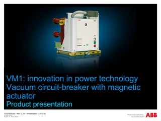
- 1. 1VCP000238 – Rev. C, en – Presentation – 2010.01 © ABB Group August 17, 2022 | Slide 1 VM1: innovation in power technology Vacuum circuit-breaker with magnetic actuator Product presentation October, 2009
- 2. VM1 Vacuum circuit-breaker with magnetic actuator Die Summe von Vorteilen Keine Wartung Wenige Einzelteile Einfache mechanische Abläufe Sehr hohe Zuverlässigkeit Hoher Qualitätsstandard Sehr hohe Lebensdauer Main Characteristics • Maintenance-free • Extremely high number of operating cycles • Electronic controller with sensor technology • Vacuum interrupters embedded in epoxy resin • High quality standard • Compatible with conventional circuit-breakers • For universal applications worldwide
- 3. VM1 VM1 Rated voltage kV 12 17.5 24 Rated current A ...2500 ...2500 ...2500 Rated short-circuit kA ...31.5 ...31.5 ...25 breaking current
- 4. VM1 Emergency manual breaking mechanism Electronic controller Magnetic actuator Capacitor Inductive sensors for position detection
- 5. VM1
- 6. VM1 Main characteristics Maintenance-free Control of the position open/closed with inductive sensors Magnetic actuator with extremely high number of operating cycles up to 100,000 operating cycles for breaking capacity up to 25 kA and rated current up to 1250 A up to 50,000 operating cycles with rated current > 1600 A and/or breaking capacity > 31.5 kA Embedding technology to protect vacuum interrupters High quality standard Interchangeable with VD4 Developed for universal applications worldwide Emergency mechanical opening operation
- 7. VM1 Functional diagram of electronic controller
- 8. VM1 -SO4 Undervoltage opening (only with ED2.0 Full Option) -SL1 Contact locking the CB closing -SO3 Auxiliary and safety open (2^ open command from remote) -SO2 Open command from remote -SC2 Close command from remote DO7 CB Remote Open DO6 Unit Not Ready DO5 Unit Ready DO2 CB closed DO1 CB open 24 .. 48V AC / 24 .. 60 V DC 100 .. 240V AC / 110 .. 250 V DC Auxiliary voltage supply
- 9. VM1 Power supply and electronic controller Capacitor Inductive sensors
- 11. VM1 Representation of magnetic flux density distribution Magnetic latching in end-of-run position Armature position: 0 mm Ampere-turns: 0 Magnetic latching and action of the magnetic field of a coil Armature position: 0 mm Ampere-turns: 12500 Moving armature in opposing position and magnetic end-of-run latching Armature position: 20 mm Ampere-turns: 5000
- 12. VM1 Reduction of the magnetic flux density of Koerdym 280 as a function of the lifetime t at an ambient temperature of 120° C
- 13. VM1 Basic version Closing pushbutton (SC1) Opening pushbutton (SO1) Mechanical operation counter Mechanical signalling device for circuit-breaker open/closed Emergency manual opening device Lever for manual emergency opening Lamp signalling “READY” for the operation (PRDY) Capacitors for storing energy for the operation Mobile connector for direct connection to the sockets of the electronic module, to cable the auxiliary circuits ED2.0 standard version control module
- 14. VM1 ED2.0 control module standard version Signalling contacts without potential, fitted with relay, with the following functions: N° 1 contact signalling circuit-breaker open (DO1) N° 1 contact signalling circuit-breaker closed (DC1) N° 1 contact signalling circuit-breaker ready for the operation (capacitors charged and check of circuit-breaker state) (DR) * N° 1 contact signalling circuit-breaker not ready for the operation (DN, normally closed) N° 1 transient contact with momentary closing during the opening operation (DOR). Remark: with the circuit-breaker not supplied (without auxiliary power supply) these contacts are open, except the contact signalling circuit-breaker not ready for the operation (DN). *Not available in some versions.
- 15. VM1 ED2.0 control module standard version 2 feeder power supply: Type 1: 24 ... 48 V AC / 24 ... 60 V DC Type 2: 100 ... 240 V AC / 110 ... 250 V DC Binary inputs (logical inputs) for remote control: N° 1 input for closing control (-SC2) N° 1 input for opening control (-SO2) N° 1 input for additional opening control (-SO3) N° 1 input for circuit-breaker opening on direct command from the protection release PR512 (-SO5) N° 1 input for lock on closing control (the same function of the locking electromagnet in the mechanical actuator of the VD4 circuit-breaker) (-SL1) Binary inputs: 24 ... 240 V AC (– 15% ... + 10%) 24 ... 250 V DC (– 30% ... + 10%) (minimum duration of the impulse is 20 ms)
- 16. VM1 ED2.0 control module standard version Functions: Self-opening following determination of incorrect state of circuit- breaker Self-opening following load threshold of the capacitors lower than the minimum value required for the opening and closing operation Anti-pumping relay function Trip-free function Monitoring of capacitor load with feeder turning itself off in the case of exceeding the maximum load level (these functions can be disabled by means of dip-switches)
- 17. VM1 ED2.0 control module full option version (on request) Signalling contacts without potential, fitted with relay, with the following functions: N° 2 contacts signalling circuit-breaker open (DO1, DO2) N° 2 contacts signalling circuit-breaker closed (DC1, DC2) N° 1 contact signalling circuit-breaker ready for the operation (capacitors charged and check of circuit-breaker state) (DR) N° 1 contact signalling circuit-breaker not ready for the operation (DN, normally closed) N° 1 transient contact with momentary closing during the opening operation (DOR) Remark: difference respect to ED2.0 control module basic version
- 18. VM1 ED2.0 control module full option version (on request) Binary inputs (logical inputs) for remote control: N° 1 input for closing control (-SC2) N° 1 input for opening control (-SO2) N° 1input for additional opening control (-SO3) N° 1 input for circuit-breaker opening on direct command from the protection release PR512 (-SO5) N° 1 input for lock on closing control (the same function of the locking electromagnet in the mechanical actuator of the VD4 circuit-breaker) (-SL1) N° 1 input as undervoltage control for (-S04) Remark: difference respect to ED2.0 control module basic version
- 19. VM1 ED2.0 control module full option version (on request) Functions: Self-opening following determination of incorrect state of circuit- breaker Self-opening following load threshold of the capacitor lower than the minimum value required for the opening and closing operation Anti-pumping relay function Trip-free function Monitoring of capacitor load with feeder turning itself off in the case of exceeding the maximum load level Undervoltage function with selection of the reference rated voltage and with possibility of delaying the opening from 0 to 5 s (-SO4) Watchdog of the electronic power circuit with feeder turning itself off in the case of overtemperature and/or overcurrent Slow capacitor charging function (the power load passes from 100 watt to 40 watt, doubling the charging time) Monitoring continuity of the opening and closing coils Watchdog (DN) Additional safety opening command function Remark: difference respect to ED2.0 control module basic version
- 20. VM1 Accessories available (on request) Signalling auxiliary contacts circuit-breaker open/closed Fixed circuit-breaker (-BB1; -BB2; -BB3; -BB8): Set of 5 make contacts plus 5 break contacts Set of 10 make contacts plus 10 break contacts (alternatively) Withdrawable circuit-breaker (-BB1; -BB2) Set of 5 break contacts plus 5 make contacts Transmitted contacts of the withdrawable circuit-breaker installed in the truck (-BT1; -BT2) These contacts are either in addition or as an alternative to the position contacts (for signalling circuit-breaker racked out) located in the unit; they also carry out the function of the position contact (-BT3) Position contact of the withdrawable circuit-breaker (-BT3) With binary input SL1 prevents remote CB closing during translation of the truck; it is supplied when the transmitted contacts -BT1; -BT2 are not required Motorised truck (-MT) (only for VM1 for UniGear panel)
- 21. VM1 Features of the control module ED2.0 (standard version) The closing coil can only be activated when VM1 is open The opening coil can only be activated when VM1 is closed Closing is disabled when an opening command is active at the same time De-activation of the opening or closing coil takes place when the relative limit position has been reached WRONG POSITION (auto trip) function: if the final CLOSED (or OPEN) position is not reached within 70 ms during a closing (or opening) operation, an opening operation is immediately started to guarantee reaching a defined safe position in any case. Anti-pumping function ensures that only one closing-opening cycle is carried out when a closing command followed by an opening command is active; active closing command must be cancelled and reset for the next closing operation. Activation of the input for the closing command can be locked by means of an external locking signal. Input for the “lock on closing” command must be energised to be able to close the circuit-breaker (without power it inhibits closing).
- 22. VM1 Features of the control module ED2.0 full version Undervoltage function controls VM1 opening if the voltage applied drops below the limit of tolerance (established by the Standards) rated voltage value to be monitored is set in the factory in conformity with the order specifications but it can be changed by dip-switches to prevent UVR intervention, when the voltage drops below the specified level (e.g. in the case of motor starting), it is possible to set a trip time UVR function can be disabled Monitoring function of the actuator closing and opening coil; if a fault is detected, the luminous “READY” signal on front of the circuit-breaker turns off and the “READY/NOT READY” signalling contacts are activated. Additional safety opening command function; the second input of the control module for the opening function is designed so that an opening command is carried out directly even in the case of a fault in the microprocessor.
- 23. VM1 Features of the capacitor The energy stored is suitable for an O-C-O operating cycle without recharging The energy stored is constantly monitored by measuring the voltage of the capacitor “READY” indication signals: application of the power supply voltage “ready” status of VM1 for the next operation “READY” signal switched on means (VM1 in the open position) energy sufficient for one C-O operating cycle (VM1 in the closed position) energy sufficient for one opening operation; energy available is sufficient for one opening operation within 60 s from interruption of the auxiliary power supply (up to 120 s with 2 capacitors)
- 24. VM1 Lifetime t of aluminium electrolytic capacitors as a function of the ambient temperature T
- 25. VM1 Characteristic data Switching energy for CO VM1: 150 J VD4: 115 J Capacitor voltage 80 V Closing cycle VM1 max. 100 J without capacitor max. 2.3 kW for 54 ms Making current max. 29 A for 44 ms Breaking capacity with capacitor max. 50 J without capacitor max. 2.1 kW for 27 ms Breaking current max. 27 A for 30 ms Opening time 35 ... 45 ms Arcing time 10 ...15 ms Total interruption time 45 ... 60 ms Closing time 50 ... 60 ms
- 26. © ABB Group August 17, 2022 | Slide 26