17 immediate placement immediate load angular correction
•
0 likes•1,954 views

The Guide Right Surgical Guide System is a system of components for the fabrication and correction of diagnostic and surgical dental implant guides in 1 or 2 dimensions.

Recommended
Recommended
More Related Content
What's hot
What's hot (20)
Similar to 17 immediate placement immediate load angular correction
Similar to 17 immediate placement immediate load angular correction (18)
Recently uploaded
Recently uploaded (20)
17 immediate placement immediate load angular correction
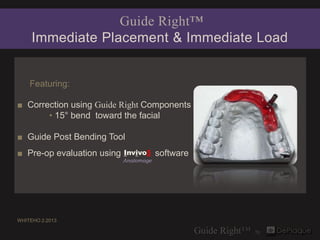
- 1. Guide Right™ Immediate Placement & Immediate Load Featuring: ■ Correction using Guide Right Components • 15° bend toward the facial ■ Guide Post Bending Tool ■ Pre-op evaluation using Invivo5 software Anatomage WHITEHO 2.2013
- 2. #11 has internal root resorption on palatal surface. An implant was recommended.
- 3. Fabrication of DIAGNOSTIC Guide 3 mm Guide Post 3 mm Diagnostic Guide Sleeve (1 cleat)
- 4. Treatment Plan: Replacement of #11 with immediate placement & temporary restoration
- 5. 3/32” drill through the existing tooth on the cast
- 6. 3 mm guide post & 3 mm diagnostic guide sleeve (1 cleat) with existing tooth remaining for the DIAGNOSTIC guide
- 7. Red wax added to tooth if cast should break when drilling to allow the DIAGNOSTIC guide to fit for the cone beam X-ray
- 8. Palatal view of beading wax added
- 9. Triad® Gel applied to capture guide sleeve cleats and adjacent teeth to form the DIAGNOSTIC guide
- 10. Invivo5 Anatomage Pre-op Software Evaluation
- 11. NOTE: # 11 Initial Alignment Each time a change is made in the software go back to the initial line up view and calculate the angle in the 2nd plane. axial cross sectional Invivo5 Anatomage Invivo5 Anatomage tangential view volumetric
- 12. # 11 Initial Alignment of guide sleeve with virtual implant Invivo5 cross sectional view Anatomage
- 13. Understanding Invivo5 Grid Measurements SOFTWARE GRID each square: 5 X 5 mm each side of the square: 5 mm center mark is 2.5 mm tangential
- 14. If the implant is placed with the guide sleeve in this position the facial wall of the bone will be violated. Therefore the axis of the guide sleeve needs to be changed # 11 CLOSE UP
- 15. # 11 indication ANGULAR CORRECTION: 15º bend toward the facial axial cross sectional Invivo5 Invivo5 Anatomage Anatomage tangential volumetric
- 16. # 11 CLOSE UP ANGULAR CORRECTION: 15° to the facial tangential cross sectional Invivo5 Anatomage
- 17. ANGULAR CORRECTIONS are made with the Guide Right™ Guide Post Bending Tool Step by step instructions at end of slideshow
- 18. Guide Right™ Guide Post Bending Tool 10 ° example For more information on use of the bending tool go to www.deplaque.com ▪ Guide Right™ Generation ll Bending Tool
- 19. 15° One bend to correct # 11 3 mm stylus placed over 3 mm guide post to make the 15° bend
- 20. # 11 Image showing 15° difference in virtual implant correction Before After Invivo5 cross sectional views
- 21. # 11 actual guide post placed on image of virtual guide post and corrected guide in place ▪ to verify 15º magnetic guide post correction ▪ One method of checking the guide post after the bend is to place the bent guide post over a print out of the view observed in the software. Invivo5 Anatomage
- 22. Review of Pre-op Corrections #11 ANGULAR CORRECTION 15º bend toward the facial
- 23. Fabrication of SURGICAL Guide 3 mm Magnetic Guide Post 3 mm Open Guide Sleeve
- 24. Existing restoration removed from cast before making SURGICAL guide
- 25. Straight magnetic 3 mm guide post in planned osteotomy hole
- 26. Corrected 3 mm magnetic guide post with 15° bend toward facial
- 27. 3 mm bent magnetic guide post showing 15° correction
- 28. Occlusal view of corrected 3 mm magnetic guide post and open guide sleeve
- 29. Initial Triad® Gel applied to capture the cleats of the open guide sleeve to form the SURGICAL guide.
- 30. Final application of gel to form the SURGICAL guide
- 31. Clinical view of implant placement
- 33. Placement of 15° angled abutment for temporary restoration
- 35. Temporary restoration 2 days later
- 36. Guide Right™ Products shown in this case 1 - 3/32” drill 1 - 3 mm Guide Post 1 - 3 mm Diagnostic Guide Sleeve (1 cleat) 1 - 3 mm Magnetic Guide Post 1 - 3 mm Open Guide Sleeve Guide Post Bending Tool Triad® Gel 1.800.314.0065 • www.deplaque.com
- 37. Guide Right™ GUIDE POST BENDING TOOL SINGLE BEND review Step 1 Place bending tool plate on a secure flat surface with the degree increments at the top & the stainless steel bar with the v-cut at the bottom. Step 2 Locate 3/32” hole in the center of the v-cut and place the bottom half of the guide post into the hole. Tighten the set screw. Step 3 Locate the hole in the bottom of the stylus that you will use that will fit over the top half of the guide post (3.0 mm, 4.0 mm or 5.0 mm). Step 4 Fit the stylus over the guide post securely with the point directed at zero degrees and the bottom of the stylus in contact with the V block. Step 5 Using the stylus as a lever, bend the guide post to the degree of angle of correction. You may need to ease the point of the stylus beyond the point of the desired degree. Step 6 Loosen screw and remove guide post and the stylus to find the guide post bent to the desired angle.
- 38. Guide Right™ GUIDE POST BENDING TOOL COMPOUND BEND overview Step 1 Position a straight or offset guide post in the bending plate, tightening the set screw against one of the flat surfaces on the lower half of the guide post. Step 2 The 1st bend can be made to the right or left direction. Step 3 The set screw is loosened and the guide post is rotated 90 ° next flat surface. Step 4 The 2nd bend in the second plane is made after rotating the guide post up away from the surface of the bending plate to register the stylus point back at 0 degrees. Step 5 Slide the stylus support bar down under the stylus until it supports the stylus. Tighten the side screws before making the second bend. Step 6 The 2nd bend can be made in either direction according to the x-ray. Step 7 Remove the stylus and place the guide post back in the cast with the appropriate side indicated by a mark facing the buccal or lingual surface. Be sure the post is in the correct position. If the post needs to be corrected by a linear movement an offset guide post can be used. Off sets available in the 3 mm guide post: 0.5,1,1.5, 2.0 ,or 3.0 mm.
- 39. A System of Components for the fabrication and correction of DIAGNOSTIC & SURGICAL guides in one or two dimensions In-office or lab fabrication Evaluate with 2D & 3D imaging Allows linear and angular correction Enables precision implant placement Cost effective 1.800.314.0065 • www.deplaque.com
- 40. Guide Right™ Surgical Guide System fabricate ▪ evaluate ▪ correct ▪ verify ▪ place Start With Precision. Place With Confidence.™ 1.800.314.0065 • www.deplaque.com