15 Other semiconductor-Photoelectronic devices.ppt
Optoelectronics is the communication between optics and electronic devices that converts electrical energy into light and light into energy through semiconductors.
15 Other semiconductor-Photoelectronic devices.ppt
1.
Electronic Devices andCircuits
by
Lecturer Waleed H. Habeeb
Lecture 15
Other semiconductor devices
1
2.
Types of OptoelectronicsDevices with
Applications
-Optoelectronics is the communication between optics and electronic
devices that converts electrical energy into light and light into energy
through semiconductors.
-Optoelectronics device is basically an electronic device involving
light. This device can be found in many optoelectronics applications
like military services, telecommunications, automatic control systems
and medical equipment.
Types of OptoelectronicsDevices
Optoelectronics are classified into different types such as:
- Photodiode
- Solar Cells
- Light Emitting Diodes
- Optical Fiber
- Laser Diodes
5.
Photo Diode
-A photodiode is a semiconductor light sensor that generates a
voltage or current when light falls on the junction. It consists of an
active P-N junction, which is operated in reverse bias. When a
photon with plenty of energy strikes the semiconductor, an electron
hole pair is created. The electrons diffuse to the junction to form an
electric field.
-Photodiodes are used in many
types of circuits and different
applications such as cameras,
medical instruments, safety
equipments, and industrial
equipments.
6.
Red LED
HR
SpO2
85
96
PI
0.8
ACCURACY OFPULSE OXIMETRY:
Photodiode
The plethysmograph
waveform shows signal
over time, corresponding
to pulse
Oxygen Saturation
value
PTT
Pulse transit time represents the
interval from ECG R wave to PPG
peak; determined by arterial compliance
Photodiode Application
7.
Solar Cells
-A solarcell or photo-voltaic cell is an electronic device that directly
converts sun’s energy into electricity.
-Sunlight, which is composed of photons, radiates from the sun. When
photons hit the silicon atoms of the solar cell, they transfer their
energy to lose electrons; and then, these high-energy electron flow to
an external circuit. The solar cell is composed of two layers which are
struck together. The advantages
of solar cells are that, there is no
fuel supply and cost problem.
These are very dependable and
require little maintenance.
-The solar cells are applicable
in rural electrification, electric
power generation system in
space and medical instruments.
8.
Solar Cells Application
-Energy harvesting has become an attractive solution for powering the
pacemaker electronics. Power can be come from ambient energy
sources such as electromagnetic signal, solar, mechanical vibration,
radio frequency (RF), and thermal energy .
- Optical charging methods utilize a photovoltaic cell integrated in the
implant devices.
- The power can be transmitted in the near-infrared (near-IR) or infrared
region and received by an array consisting of photovoltaic cells.
- Light typically has low
interactivity with biological
tissues.
9.
Light-Emitting Diodes
-Light-emitting diodeis a P-N semiconductor diode in which the
recombination of electrons and holes yields a photon. When the diode
is electrically biased in the forward direction, it emits narrow spectrum
light. This effect is called as electroluminescence. The color of the
light is decided by the energy band gap of the material.
The usage of LED is advantageous
as it consumes less power and
produces less heat. LEDs last
longer than incandescent lamps.
LEDs could become the next
generation of lighting and used
anywhere like in indication lights,
computer components, and
medical devices.
10.
LED phototherapy
- LEDphototherapy systems, are the newest devices used to provide
phototherapy. LEDs emits high-intensity light in the blue-green portion of
the spectrum within a narrow wavelength (460-485 nm). LEDs offer some
advantages to other phototherapy sources. Their narrow wavelength of
emission is close to the wavelength at which light is maximally absorbed
by bilirubin. Additionally, the spectral quality of the LED device can be
customized by the use of varying proportions of blue, blue-green, and
green LEDs. Also, LEDs generate
less heat than either halogen or
fluorescent lamps, and can thus
be positioned very close to the
skin without significant risk of
overheating or burns.
11.
Optical Fiber
• Anoptical fiber or optic fibre is a plastic and transparent fiber made
of plastic or glass. It is somewhat thicker than a human hair. It can
function as a light pipe or waveguide to transmit light between the
two ends of the fiber.
• Optical fibers usually include three concentric layers: a core, a
cladding and a jacket. The core, a light transmitting region of the
fiber, is the central section of the fiber, which is made of silica.
• Cladding, the protective layer around the core, is made of silica.
This creates an optical waveguide that limits the light in the core by
total reflection at the interface of the core-cladding.
• Jacket, the non-optical layer around the cladding, typically consists
of one or more layers of a polymer that protect the silica from the
physical or environmental damage.
12.
-These cables areused in telecommunications, sensors, fiber lasers, bio-
medicals and in many other industries.
- The advantages of using optical-fiber cable include their higher bandwidth,
less signal degradation, weightlessness, cost-effectiveness, flexibility, and
hence they are used in medical and mechanical imaging systems.
13.
ENDOSCOPE
Micro-camera attached toeyepiece
and image viewed on a monitor.
Uses Charge-Coupled Devices (CCD)
to Capture and store image data.
2D array of individual elements that
can store an electric charge.
can respond to as high as 70% of the
incident light.
Optical Fiber Application
14.
Laser Diodes
-Laser (lightamplification by stimulated emission of radiation) is a
source of highly monochromatic, coherent and directional light.
The function of a laser diode is to convert electrical energy into light
energy like infrared diodes or LEDs. The beam of a typical laser has
0.6mm Dim extending at a distance of 15 meters. The most common
lasers used are semiconductor lasers.
-When a voltage is applied across the P-N junction, the population
inversion of the electrons is produced, and then the laser beam is
available from the semiconductor region. The ends of the P-N junction
of the laser diode have polished surface, and hence, the emitted
photons reflect back to create more electron pairs. Thus, the photons
generated will be in phase with the previous photons.
16.
• The abovephoto shows a variety of low-power
semiconductor laser diodes set in several different
types of casings.
17.
Medical Lasers Applications
-Laser of popular use in medicine are the solid state laser, the gas
laser, the carbon dioxide CO2 and recently the dye (liquid) laser.
- Lasers in Ophthalmology
Hyperopic Correction
18.
Thyristor
Thyristor defines abroad range of solid state components which are
used as electronically controlled switches.
Thyristors are capable of handling more power than BJTs or FETs
and also operate more efficiently in the controlling of electrical
power.
The most commonly used types of thyristors are the silicon
controlled rectifier (SCR) and the bidirectional triode (TRIAC).
Unlike the BJT which has two junctions,
the SCR has three junctions and has four
alternately doped semiconductor layers .
It is used as a switch.
19.
Thyristor
Two transistors thatform the SCR can be represented by the
schematic drawing shown below, however the circuit symbol is
represented by the symbol to the far right.
The diagram below shows a properly biased
SCR with a switch to control the gate
voltage from the source voltage and
resistor RG.
The resistor is used to limit the gate
current to a specific value, in this
case IG.
20.
When using aSCR to control the application of AC power the device
is capable of operating on only one alteration of each input cycle
(the alterations that make the anode positive).
AC Thyristor Circuit
DC Thyristor Circuit
21.
Defibrillators
A defibrillator isused to stop uncoordinated heart beats of a massive
heart attack by delivering a controlled electric shock on the patient's
chest.
A biphasic discharge curve. The discharge curves of two capacitors is cut
into two pieces. The areas of the two parts correspond to the set energy.
22.
- The defibrillatorconsists of a high voltage power supply, a large capacitor as
an energy storage, a relay for switching over from charge to discharge, a control
unit, an ECG and the two paddles. A high voltage power supply HVPS starts to
charge up the high voltage capacitor (typically 15 μF - 40 μF) .The charge voltage
depends on the position of the energy rotary switch S2. Usually energies between 2 J
and 360 J can be set. This corresponds with a charge voltage of between 300 V and
5000 V. The following simplified circuit diagram shows how thyristors are used to
trim the signal of Modern biphasic defibrillators and to charge and discharge the
capacitors.
23.
The Triac hasthe same switching characteristics as an
SCR but in both directions, it is the equivalent of two
SCRs in parallel connected in opposite directions.
The triac is a 4 layer
NPNP device in
parallel with a
PNPN device.
Triacs and Diacs
24.
The equivalent circuitof a triac shows two SCRs connected in
parallel but in opposite directions.
The triac is designed to respond to the currents that flow through
it’s single gate terminal to control both SCRs.
The triac controls current flowing in either direction, this design is
used to control AC power to various types of loads or circuits.
The schematic symbol
is labeled as MT1 and
MT2.
Triacs and Diacs
25.
An SCR alwaysrequires a positive gate voltage but the TRIAC can
be triggered by either a positive or a negative gate voltage.
In order to create a triggering current, a positive or negative voltage
has to be applied to the gate with respect to the MT1.
Below is a typical triac circuit used to vary the amount of AC power
applied to a load.
The triac is triggered into conduction on both the positive and
negative alterations of each
AC input cycle.
Triacs and Diacs
26.
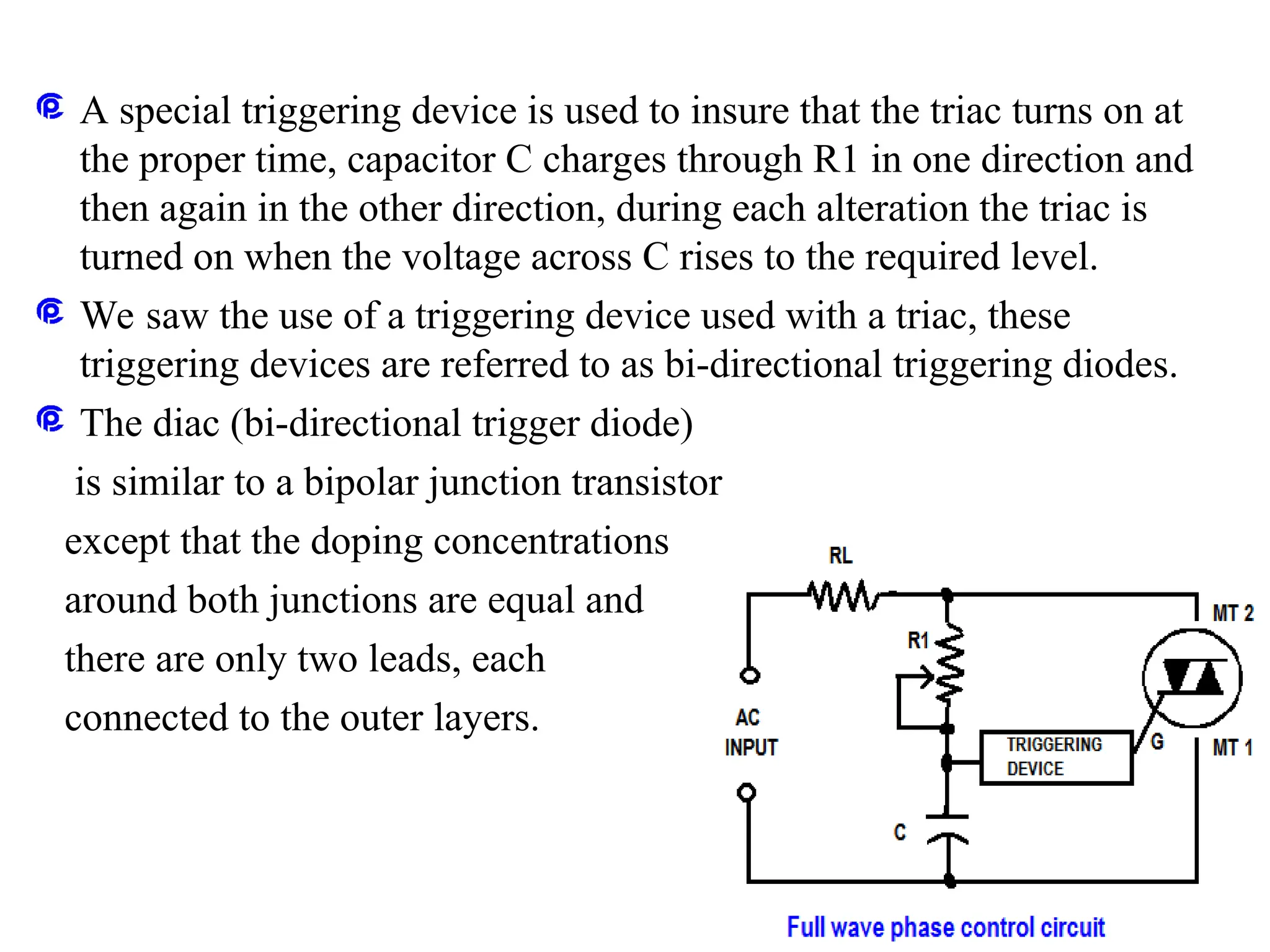
A special triggeringdevice is used to insure that the triac turns on at
the proper time, capacitor C charges through R1 in one direction and
then again in the other direction, during each alteration the triac is
turned on when the voltage across C rises to the required level.
We saw the use of a triggering device used with a triac, these
triggering devices are referred to as bi-directional triggering diodes.
The diac (bi-directional trigger diode)
is similar to a bipolar junction transistor
except that the doping concentrations
around both junctions are equal and
there are only two leads, each
connected to the outer layers.
27.
The diac hasno middle lead and resembles a regular PN junction
diode.
A diac will always be forward biased while the other is reverse biased,
the reverse biased junction controls the current flowing through the
diac.
The diac remains in an off state until the applied voltage in either
direction is high enough and the reverse biased junction reaches it’s
breakdown voltage.
The diac then turns on and current rises until
it is limited by a series resistance, so the
diac acts like a bi-directional switch.
Triacs and Diacs
28.
The diac isused in conjunction with a triac as a triggering device to
provide full wave control of AC signals.
commonly used, in controlling the speed of low-power induction
motors, in dimming lamps and in controlling AC heating resistors.
Triacs and Diacs